A Modified PI-Like Fuzzy Logic Controller for Switched Reluctance Motor Drive
Shun-Chung Wang* Yi-Hua Liu Chia-Cheng Lee
Department of Electrical Engineering, Department of Electrical Engineering, Department of Electrical Engineering, Lunghwa University of Science National Taiwan University of Science Lunghwa University of Science
& Technology, Taoyuan, Taiwan & Technology, Taipei, Taiwan & Technology, Taoyuan, Taiwan e-mail: [email protected]
Abstract—Based on the redevelopment of control rule base, a modified type PI-like fuzzy logic controller with output scaling factor (SF) self-tuning mechanism is proposed and experimentally testified in this paper for application in the switched reluctance motor (SRM) drive system. This paper aims to simplify the structure hierarchy and computational complexity of the controller by reducing the number of fuzzy sets in the membership function (MF) but still without losing the system performance and stability. For the proposed controller, the output scaling factor can be tuned continuously by a gain updating factor, whose value is derived from the fuzzy logic reasoning with the error and change of error of the plant as the input variables. The rule base is built based on the practical understanding and knowledge of the SRM’s basic dynamic behavior, operating mode and experimental experience. Various aspects of the design considerations about the membership function, rule base, and gain tuning strategy are described in detail. Experiments and results comparison carried out on a four phase 8/6 pole SRM based on the platform of dSPACE DS1104 control desk are given to show the feasibility and effectiveness of the devised methods as well as support the theoretical considerations.
Keywords-fuzzy logic controller; scaling factor; switched reluctance motor
I. I
NTRODUCTIONWith the advances in power electronics and high-end control techniques, as well as the development of high-speed micro controller unit (MCU) with powerful digital computation capability, the switched reluctance motor drives are under consideration in various applications requiring high performance such as in servomotor drives, electric vehicle propulsion and jet engine starter-generators etc. Switched reluctance motors inherently feature numerous merits like simple and rugged structure, high torque-inertia ratio, fault- tolerance robustness, capability to run in abominable circumstances [1] etc. However, due to the doubly salient structure and excessive saturation, the machine presents a highly nonlinear plant, and the performance of the SRM is naturally affected by the non-linearity of the magnetic circuit.
On the other hand, the induced electromagnetic torque varies nonlinearly with the rotor position because of the deeply magnetic saturation. The higher torque ripple compared with conventional machines is the main shortcoming and hence limits the SRM application as a servo drive. In addition, modeling a SRM is not easy via traditional skills because its
flux linkage, inductance, and torque possess highly coupling with rotor position and phase current. Therefore, analytical methods or computer-based experimental determinations [2], [3] are widely utilized to predict and characterize the magnetization curves of the SRM.
At present the advanced proportional, integral and/or derivative (PI, PD, PID) controllers have been proven well control performance for many industrial drives [4], [5].
However, the performance may be significantly deteriorated while the alteration in operating condition or the drift of parametric property due to the component aging or the change of working environment. When the exact analytical model of the controlled system is uncertain or difficult to model, intelligent control techniques such as fuzzy logic control (FLC) may allow better performance [6]-[8]. Fuzzy logic control can translate linguistic control rules into practical operation mechanism, and it features a good prospect to take robustious and adaptive nature in the control of a nonlinear process by using a heuristic logical model of the specialist behavior. FLC has been found particularly available for controller design when the plant is difficult to model mathematically, hence, it is widely applied in a considerable variety of engineering fields today, such as motor drives [9]-[10].
In this paper, a modified fuzzy PI-like controller with gain self-tuning mechanism by altering a gain updating factor is presented for the SRM drive system. A modified rule base has been developed to simplify the program hierarchy and computational burden of the controller by reducing the number of fuzzy sets in the membership functions but still without losing the system performance and stability. The rule base is rebuilt on the fuzzy control rules which are derived from the practical understanding and knowledge of the SRM’s basic magnetization behavior, operating mode and experimental experience with the speed error and change of error as input variables. The remainder of this paper is organized as follows.
Section II simply introduces the SRM’s dynamic behavior
model and the drive system architecture. The basic principle of
the fuzzy logic controller, the control structure, the design
procedure and the self-tuning strategy of the proposed
controller are expounded in detail in Section III. Experimental
results and comparisons, under various operating conditions
and load disturbances, are carried out in Section IV. Finally,
conclusions from practical observation and test of the SRM
drive system are included in Section V.
II. SRM D
RIVES
YSTEM A. SRM Behavior ModelIn the SRM, the flux linkage, inductance, and torque possess highly coupling and non-linear with the variation of rotor position and phase current, and hence its magnetization characteristics and operating behavior are difficult to decouple and model mathematically. Fig. 1(a) and (b) show the cross- section profile of a four-phase 8/6 pole SRM and its equivalent circuit of one phase winding, respectively. The equivalent circuit can be represented by a resistance R in series with an inductance L(i, θ ) which is a function of rotor position θ and excitation current i. From Fig. 1(b), if the magnetic coupling effect between two phases is taken into account, the dynamic behavior of the m-phase SRM can be expressed by
Fig. 1. (a) Cross section and (b) equivalent circuit of an 8/6 poles SRM.
1
, 1, 2,
=
⎧⎛ ∂ ⎞ ⎛ ∂ ⎞ ⎫
⎪ ⎪
=
∑
m ⎨⎪⎩⎜⎝ +ω∂θkj⎟⎠ +⎜⎜⎝ + ∂kj⎟⎟⎠ j⎬⎪⎭ = "k k j kj j
j j
L L di
v R i L i k m
i dt
(1)
Where ω is the rotor angular velocity and m is the phase number.
The co-energy of the SRM is equal to the area enclosed by the flux linkage versus current ( λ -i) curve over one excitation cycle. For a specified current, the induced electromagnetic torque can be obtained by differentiating the co-energy with respect to the rotor position, θ , which can be described as
0 constant
( , )
i( , )
e
i
T i
θ θ λ θ
i di =∂ ⎡ ⎤
= ∂ ⎢ ⎣ ∫ ⎥ ⎦ (2) Here define an incomplete torque function as
1
1 sgn( , ) , 1, 2,
2
m kj
k j
j
T k j i dL k m
d
θ
=
⎧ ⎫
= ⎨ ⎬ =
⎩ ⎭
∑ " (3)
Where sgn(k, j) = 1 if k=j and sgn(k, j) = -1 if k≠j. From (2) and (3), the produced totally electromagnetic torque can be denoted as
1 m
e k k
k
T i T
=
= ∑ . The mechanical torque of the rotor can be expressed as
mec e
T T B Jd
dt
ω ω
= − − (4) where J, B, and T
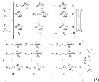
mecstand for the machine’s moment inertia, friction coefficient, and mechanical torque of rotor, respectively. Together with (1), (3), and (4), the matrix-form behavior model of the SRM with taking the effect of the magnetic coupling into consideration can be denoted by (5). If the mutual inductance is negligible, thus L
kj= 0 if k≠j and L
kj≠ 0 if k=j.
1
11 12
1
1 21 22 2 1
2 2 2
1 2
1 2
11 12
11 1 12 2
1
( ) 0
( ) 0
0
( ) (
ω ω ω
θ θ θ
ω ω ω
θ θ θ
ω θ ω θ ω θ ω
∂
∂ ∂
⎡ ⎤
⎢ + ∂ ∂ ∂ ⎥
⎢ ⎥
⎡ ⎤ ⎢ ∂ + ∂ ∂ ⎥⎡ ⎤
⎢ ⎥ ⎢ ∂ ∂ ∂ ⎥⎢ ⎥
⎢ ⎥ ⎢ ⎥⎢ ⎥
⎢ ⎥= ⎢ ⎥⎢ ⎥
⎢ ⎥ ⎢ ∂ ∂ ∂ ⎥⎢ ⎥
⎢ ⎥ ⎢ ⎥⎢ ⎥
⎢ ⎥ ⎢ ∂ ∂ ∂ ⎥⎢ ⎥
⎣ ⎦ ⎣ ⎦
⎢ − ⎥
⎢ ⎥
⎢ ⎥
⎣ ⎦
∂ ∂
+ +
∂ ∂
+
"
"
# # # # # #
"
"
m
m
m m m mm m
mec
m
L
L L
R
v L R L L i
v i
v L L L i
T
T T T B
L L
L i L i
i
1 1 2
2 1
21 22
21 1 22 2 2
1 2 2
1 2
1 1 2 2
1 2
) ( ) 0
( ) ( ) ( ) 0
( ) ( ) ( ) 0
0 0 0
ω
∂
⎡ ⎤
⎢ + ∂ ⎥
⎢ ⎥
⎢ ∂ ∂ ∂ ⎥ ⎡ ⎤
+ + +
⎢ ∂ ∂ ∂ ⎥ ⎢ ⎥
⎢ ⎥ ⎢ ⎥
⎢ ⎥ ⎢ ⎥
⎢ ⎥ ⎢ ⎥
∂ ∂ ∂
⎢ + + + ⎥ ⎢ ⎥
⎢ ∂ ∂ ∂ ⎥ ⎢ ⎥⎣ ⎦
⎢ ⎥
−
⎢ ⎥
⎢ ⎥
⎢ ⎥
⎣ ⎦
"
"
# # # # #
"
"
m
m m
m m
m m
m
m m mm m
m m mm m
m
L i L
i i
L i
L L
L i L i L i
i i i i
d
L L L dt i
L i L i L i
i i i
J
(5)
B. Drive System ArchitectureShown in Fig. 2 is the configuration of the SRM drive system. It consists of four controllers (fuzzy speed controller, PI current controller, exciting angle regulation controller, and commutation logic controller), gate driver circuit with photo- couplers, power inverter, and the four-phase 8/6 pole SRM under control. The fuzzy speed controller receives the speed error signal and converts it into four-phase current commends that will be sent to the current controller. The actual current, sensed by the Hall-effect sensor, is compared with current commend to obtain the current error. According to the error value, the pulse-width-modulation (PWM) gating signals of IGBT switches in asymmetric half-bridge-type power inverter are generated by the conversion of current controller. The gating signals drive the power inverter through the photo- couplers isolation to control the SRM. Where the commutation logic controller is used to derive and determine the phase commutation moment of the SRM. To simplify the hardware complexity, all of the four controllers are implemented in a DSP-based develop board DS1104 which is embedded in the control desk of the dSPACE company.
Fig. 2. Architecture of the SRM drives system.
III. F
UZZYL
OGICC
ONTROLLERD
ESIGNIn this section, the key point of self-tuning PI-like fuzzy
controller (STFC) is reviewed simply, and then the modified
design of the STFC with rule base combination of controller-
output rule and updating-factor rule is presented. Various
aspects of the design considerations about membership
function, rule base, and the gain tuning strategy are described in detail.
A. Self-Tuning FLC
The configuration of a conventional PI-like fuzzy controller (PIFC) and a self-tuning PI-like fuzzy controller are shown in Fig. 3 and Fig. 4, respectively. The main difference between both controllers is that the STFC includes another control rule base for the gain updating factor α [8]. A FLC which fine tunes a properly working controller by altering either its MFs or SFs or, both of them is called a self-tuning FLC.
Fig. 3. Block diagram of the conventional PI-like fuzzy controller.
Fig. 4. Block diagram of the self-tuning PI-like fuzzy controller.
Here a discrete-time controller with two inputs and a single output is considered. From Fig. 4, the error e and change of error Δe are used as the input variables, which are defined as
( ) = ( ) − ( )
e k r k y k
and Δ
e k( ) =
e k( ) −
e k( − = 1)
y k( -1) - ( )
y k if r(k) = r(k-1), respectively. Where r and y denote thereference command and plant output, respectively. Indices k and k-1 respectively express the current state and the previous state of the system. The controller output is the incremental change of the control signal, Δu(k). The control signal can be obtained by ( )
u k=
u k( − + Δ 1)
u k( ) .
The universe of discourse in all membership functions of the controller inputs, e and Δe, and the output, Δu, are defined on the normalized domain [-1, 1] as shown in Fig. 5. The linguistic values NB, NM, NS, ZE, PS, PM, and PB stand for negative big, negative medium, negative small, zero, positive small, positive medium, and positive big, respectively. On the other hand, the universe of discourse for the gain updating factor α (which is applied to fine tune the output SF) is normalized over the interval [0, 1] as shown in Fig. 6. The linguistic values ZE, VS, S, SB, MB, B, and VB represent zero, very small, small, small big, medium big, big, and very big, respectively. Here except the two fuzzy sets at the outmost ends (trapezoidal MFs are considered), symmetric triangles with equal base and 50% overlap with adjacent MFs are chosen.
The scaling factors G
e, G
Δeand G
Δu, which perform the specific normalization and de-normalization of input and output variables, play a role equivalent to that of the gains of a conventional controller. The values of the actual inputs are
mapped onto [-1, 1] by the input SFs, G
eand G
Δe, respectively.
The actual output of the self-tuning FLC is obtained by using the effective SF, αG
Δu[8]. Hence, adjusting the scaling factors can modify the corresponding universe of discourses of control variables.
Fig. 5. Membership functions of E, ΔE, and ΔU.
Fig. 6. Membership function of gain updating factor α.
As shown in Fig. 4, the relationships between the SFs and the input and output variables of the STFC can be obtained as follows:
, , ( )
N e N e u N
e
=
G e eΔ =
GΔΔ Δ =
e uα
GΔΔ (6)
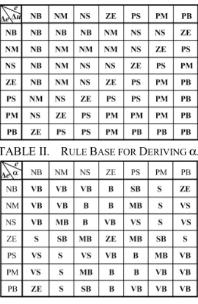
uThe rule bases for computing controller output Δu and gain updating factor α are shown in Table 1 and 2, respectively.
This is a common used rule base designed with a two- dimensional phase plane [6]. The forms of the rules that are used for Δu and α can be described respectively by
TABLE I. RULE BASE FOR DERIVING ΔU.
TABLE II. RULE BASE FOR DERIVING α.
R
Δu: If e is E and Δe is ΔE then Δu is ΔU.
R
α: If e is E and Δe is ΔE then α is α.
B. Self-Tuning FLC with Combined Rule Base
In order to reduce the numbers of control rules further to
simplify the program hierarchy and implementation complexity
of the controller, a modified union rule base with fewer control
rules, which incorporated rule base of controller output (Δu)
with the rule base of gain updating factor (α), is devised to
reduce the requirements of programming and computational
burden of the used control chips. The controller output gain can
be tuned continuously on-line with assistance of the regulation
of the implied updating factor α
i. Here we call it implied updating factor because it is integrated and embedded into the union rule base. Basic logical conception and principle of how to combine the two rule bases are described as follows.
1) A different linguistic value of the controller output should be defined for each distinct combination of linguistic values for Δu and α as demanded in Table I and II, for example, when e is PB and Δe is NS then Δu is PM (Table I) and α is VS (Table II), so the pair (PM, VS) gives a distinct combination. From the linguistic pair (PM, VS), we deduce that the trend of controller output should be positive small, i.e., we can define a control rule has the form as: If e is PB and Δe is NS then the combined controller output Δ u
αiis PS. To reason by analogy, the rule bases of Δu and α can be integrated into a modified union rule base based on this inferential conception.
2) In some situations like when e is NS and Δe is PB then Δu is PS and α is SB, so the pair (PS, SB) gives another distinct combination. From the linguistic pair (PS, SB), a control rule can be defined as: If e is NS and Δe is PB then combined output Δ u
αiis PVS. When e is PM and Δe is NB then Δu is NS and α is S, form the linguistic pair (NS, S), we can define a control rule as: If e is PM and Δe is NB then combined output Δ u
αiis NVS. Where the PVS and NVS are new linguistic values, hence they must be redefined and added to a new MF as shown in Fig. 7 for example.
Fig. 7. Membership functions of combined output uαi
Δ .
3) From Fig. 7, in order to enhance the sensitivity and
resolution of the controller around the steady state ( e ≈ 0) and take the nonlinear controller output into account, the fuzzy sets in the vicinity of ZE are more concentrated than the other ranges. The range modification of universe of discourse nearby the setpoint will prevent system response from excessive oscillation and enhance the convergence rate of the response.
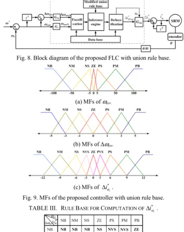
Based on the analytic conclusions above and the redefinition of universe of discourse of input and output variables, a self-tuning fuzzy controller with a modified union rule base is developed. The controller configuration is shown in Fig. 8. The controller’s input variables are ω
errand Δω
errand the output variable is the current command Δ i
α*i. The universe of discourse of input and output variables are [-100, 100]
(rpm), [-5, 5] (rpm) and [-12, 12] (A), respectively. The MFs of ω
err, Δω
errand Δ i
α*iare illustrated in Fig. 9(a)-(c), respectively.
The devised union rule base for the controller output Δ i
αiis shown in Table III. It mainly derived from integrating Table I and II and involving two new linguistic values, PVS and NVS.
In addition, the well-known Mamdani type inferential method cooperating with the popular center-of-area (COA) defuzzification procedure is utilized to produce the crisp controller output.
Fig. 8. Block diagram of the proposed FLC with union rule base.
(a) MFs of ωerr.
(b) MFs of Δωerr.
(c) MFs of * iαi
Δ .
Fig. 9. MFs of the proposed controller with union rule base.
TABLE III. RULE BASE FOR COMPUTATION OFΔiα*i.
C. Gain Tuning Strategy
The PI-like fuzzy controller without scaling gain tuning mechanism may result in low controller resolution when the speed error is small. Here the attention is focused on the tuning of output scaling gain because it has dominant influence on the system response.
a) Variation effect of input and output SFs: The effect of SFs modulation is equivalent to extend or shrink the actual universe of discourse of the input and output variables.
When G
eincreases the distribution of universe of discourse
of e will be shrunk, and thus make the response more
rapidly. When the G
edecreases the range of universe of
discourse of e will be spread, and the error has less impact
on the controller. Similarly, the effect of G
Δechange will
result in the same way as the alteration of G
edoes. The gain
used to transfer Δ u
Nto the actual output value (Δ u ) is the
output SF, αG
Δu. When the αG
Δuincreases, the universe of
discourse of Δ u will be expanded, and the actual value of
controller output will be increased too, consequently the
controller will hold more dramatic impact on the plant and
the speed of dynamic response also will be enhanced. When the αG
Δuis reduced, the overshoot is decreased and system stability will be improved. Practical tests are carried out on the SRM drive system to verify the above analyses and descriptions. The results, as shown in Fig. 10, demonstrate that the SF’s tuning do have dominant effect on the controller performance. Especially, the output SF possesses more notable impact on the system response than the input SFs.
(a) With different input SFs. (b) With different output SFs.
Fig. 10. Effect of the SFs variation.
b) Self-Tuning Mechanism: As mention above, we know that the effect of the input SFs tuning gives less impact on system performance than output SF tuning. Here we concentrated on the output SF tuning to modify the controller gain by altering the updating factor α
iin the proposed controller. The tuning mechanism is described as follows.
• Step1: Set α
ias 1.0, and obtain the most suitable values of G
e, G
Δeand G
Δuusing Simplex method [11] based on the precise understanding and knowledge of the plant.
According to the respective defined domain of SFs, the properly initial values of G
e, G
Δeand G
Δucan be obtained by
,max/ min ,max
max
, ,
err err
e e u
err err
G G G u
u
ω ω
ω
Δω
ΔΔ Δ
= = =
Δ Δ (7)
If the good transient response of the drive system without gain tuning is reached, then an appropriate initial operating condition is obtained.
• Step2: Keep the values of G
e, G
Δeand G
Δusame as those of in Step 1, then begin to tune the updating factor. In this step, the controller output and updating factor can be expressed as
( )
i( )(
u u)
Nu k α k k G
Δ Δu
Δ = Δ (8) ( )
i( ( ), ( ))
i
k f e k
αe k
α = Δ (9) Where the f
αiis a nonlinear function defined on the e and Δe. k
Δuis times of G
Δu. Here, the G
Δuis set k
Δutimes greater than that obtained in Step 1 to maintain the same rise time as that of its conventional counterpart and realize the overall performance specifications. The determination of k
Δuis empirically. A large value of (k
ΔuG
Δu) is allowable in the proposed scheme to counteract the effect that α always lines in [0, 1] to guarantee a faster response but relatively small overshoot.
• Step 3: If necessary, fine tune the rules of α
ibased on the response wanted to reach and the particular requirement wanted to considerate. Hence, the proper α
iis obtained from various operating conditions to fine adjust the output SF on-line.
IV. E
XPERIMENTALR
ESULTSThe design controllers are implemented on the real SRM drive system to view the system dynamic behavior and verify the feasibility and effectiveness. The speed tracking ability and robustness of instant loading and unloading are tested to evaluate the drive system performance. The experimental specifications and parametric values are as follows: dc-bus voltage is 100 V; switching frequency is 30 kHz; PI-type current controller with parameters k
pc=0.005 and k
ic=5; the initial values of proper SFs used in the controller are G
e=0.15, G
Δe=0.2 and G
Δu=20, respectively.
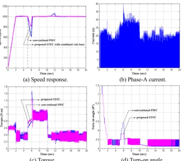
For the speed tracking test, the speed reference is mapped out from standstill to 1000 rpm, next the setpoint is changed to 500 rpm at time t=5s, and then it returns to 1000 rpm at t=10s.
The measured speed response is shown in Fig. 11(a), and Fig.
11(b), (c) and (d) show the responses of phase-A current, the output torque, and the modulation of exciting turn-on angle, respectively. From the speed tracking response, we can see that the two controllers can satisfactorily meet the speed request of the setpoint change as well as they present very good overshoot and steady-state error against speed variations. However, the proposed controller has better speed tracking capability than the conventional counterpart. The conventional PIFC takes longer delay time than that of the proposed controller to follow the speed setpoint change. From Fig. 11(b) and (c), we can obviously find out the corresponding relationship between the current and torque response under the speed change. The turn- on angle tuning for the two controllers is appropriate and exactly responds to the speed change.
(a) Speed response. (b) Phase-A current.
(c) Torque. (d) Turn-on angle.
Fig. 11. Comparison of measured dynamic responses between the proposed STFC and the conventional PIFC under the speed tracking test.
Next, to demonstrate the stability and robustness of the
proposed controller, the test of instant loading and unloading
are measured. Corresponding to the load disturbance change, the measured dynamic responses are shown in Fig. 12(a)-(d) respectively. In this case, the SRM starts with based load 0.4 N-m and speed command 1000 rpm, when the speed agrees with the setpoint, the load torque is sudden change from 0.4 N- m to 1 N-m at t=5s and then unloaded back to 0.4 N-m at t=10s. From the speed response, we can see that two controllers show good speed regulation and robustness against load variations. However, the control action of the proposed controller is more enterprising than the PIFC, particularly at the instant of loading and unloading. Therefore, the undershoot of the proposed scheme is smaller than conventional PIFC (the undershoot gap is greater than 400 rpm). From the variation correlation between the current and torque response (Fig. 12(b) and (c)), it is noted that at the loading moment, the torque overshoot of the conventional PIFC is smaller than that of the proposed controller. This is caused by the instant increase of the output scaling gain. The controller tunes the updating factor to respond and cover the instant change of load. Averagely, the torque ripple induced by the proposed controller is less than that induced by the PIFC. Finally, from Fig. 12(d), the tuning deviation of the turn-on angle at the steady state is almost fixed to an incremental angle, but nearby the time of the sudden load change the turn-on angle has a bigger regulation to provide the specified current to meet the load change.
(a) Speed response. (b) Phase-A current.
(c) Torque. (d) Turn-on angle.
Fig. 12. Comparison of measured dynamic responses between the proposed STFC and the conventional PIFC under the load change.
V. C
ONCLUSIONSIn this paper, a modified fuzzy PI-like controller with gain self-tuning mechanism by altering a gain updating factor has been devised and testified experimentally for the SRM drive system. Based on the redevelopment of control rule base, a union rule bases is proposed to simplify the program hierarchy and computational burden of the controller by reducing the number of fuzzy sets of the MFs but still without losing the
system performance and stability. Here, attention is focused on the tuning of output SF owing to its stronger impact on the system performances. In addition, the proposed controller also can reduce the computational requirement of the used MCU or DSP and simplify the complexity of control system due to its more concise architecture.
Based on the he platform of dSPACE control desk DS1104, practical tests on a four phase 8/6 pole SRM under the speed setpoint change and load disturbance have been carried out to measure various performance indices. From the experimental verification under the setpoint change of the speed and load, we can summarize that, for the speed response, the rise times for both conventional PIFC and the proposed STFC are maintained almost at the same value but with a considerably reduction in undershoot or overshoot and much improved overall performance in case of the proposed STFC. Moreover, the practical testing results also show that the proposed scheme, in each case, outperforms its conventional counterpart on the various measured performances.
A
CKNOWLEDGMENTThis work was supported by the National Science Council of Taiwan under grant Contract NSC 98-2221-E-262-020.
R
EFERENCES[1] R. Krishnan, Switched Reluctance Motor Drives: modeling, simulation, analysis, design and applications, London: CRC Press, 2001.
[2] D.N. Essah and S.D. Sudhoff, “An improved analytical model for the switched reluctance motor,” IEEE Trans. Energy Conversion, vol. 18, no. 3, pp. 349-356, Sept. 2003.
[3] R. Gobbi, N. C. Sahoo, and R. Vejian, “Experimental investigations on computer-based methods for determination of static electromagnetic characteristics of switched reluctance motors,” IEEE Trans. Instrum.
Meas., vol. 57, no. 10, pp. 2196-2211, Oct. 2008.
[4] S. Skoczowski, S. Domek, K. Pietrusewicz, and B. Broel-Plater, “A method for improving the robustness of PID control,” IEEE Trans. Ind.
Electron., vol. 52, no. 6, pp. 1669-1676, Dec. 2005.
[5] H. Zhang, “Speed control of two-inertia system by PI/PID control,”
IEEE Trans. Ind. Electron., vol. 47, no. 3, pp. 603-609, June 2000.
[6] H. X. Li and H. B. Gatland, “A new methodology for designing a fuzzy logic controllers,” IEEE Trans. Syst. Man Cyber., vol. 25, no.3, pp. 505- 512, March 1995.
[7] Y. Zhao and E.G. Collins, Jr., “Fuzzy PI control design for an industrial weigh belt feeder,” IEEE Trans. Fuzzy Syst., vol. 11, no. 3, pp. 311-319, June 2003.
[8] R. K. Mudi and N. R. Pal, “A robust self-tuning scheme for PI- and PD- type fuzzy controllers,” IEEE Trans. Fuzzy Syst., vol. 7, no.1, pp. 2-16, Feb. 1999.
[9] M. Chen, Q. Sun, and E. Zhou, “New self-tuning fuzzy PI control of a novel doubly salient permanent-magnet motor drive,” IEEE Trans. Ind.
Electron., vol. 53, no. 3, pp. 814-821, June 2006.
[10] S. Mir, M. E. Elbuluk, and I. Husain, “Torque-ripple minimization in switched reluctance motors using adaptive fuzzy control,” IEEE Trans.
Ind. Appl., vol. 35, no. 2, pp. 461-468, March/April 1999.
[11] J. A. Nelder and R. Mead, “A simplex method for function minimization,” The Computer Journal., vol. 7, pp. 308-313, 1965.