國立臺灣大學理學院化學研究所 碩士論文
Department of Chemistry, College of Science National Taiwan University
Master Thesis
二氧化矽奈米空心球之調控及其生物應用 Engineering and Bio-applications of
Hollow silica nanospheres
郭乃元 Nai-Yuan Kuo
指導教授:牟中原 博士 Advisor: Chung-Yuan Mou, Ph.D.
中華民國 105 年 7 月 July, 2016
謝誌
兩年的碩班生活就像一部兩小時的電影,在濃縮的時空中交織著夢想的地圖、
努力的汗水以及甜美的果實。記得剛開始做研究時,像是無頭蒼蠅一般盲目的嘗試;
如今面對不同的問題,我能夠自己釐清問題並擬定解決策略,一步一步解決問題,
這兩年的訓練不只是專業領域的知識,更是培養我面對未來人生關卡的積極態度。
謝謝牟老師總是讓我有許多發揮空間,讓我接觸不同領域的研究,大大的開拓 我的視野;謝謝思翰學長一路帶著我做研究,不辭心煩的與我討論,也給我生活上 的寶貴經驗;謝謝奕平學長、政勳學長在生物實驗的幫助,讓我們的研究更豐富有 趣;謝謝琨哲學長引領我到不同的研究領域,更耐心的教導我新技術;謝謝之誠學 長、明翰學長及哲睿學長在實驗室的幫忙與生活經驗的分享;謝謝正安、姿穎、怡 雯及承勳在我碩一時給我許多鼓勵與陪伴;謝謝我的同學榮麟與怡婷,我們互相鼓 勵一同奮戰到最後;謝謝榮坤、柔暄、庭瑋與憶慈的陪伴,有你們在實驗室生活變 的有趣;謝謝師大劉老師時常關心我的生活與實驗,謝謝師大的夥伴我們一起創造 許多青春的回憶;謝謝語柔,從大學到碩班我們一起成長茁壯、互相扶持,希望能 夠一起創造更多未來。感謝一路以來所有幫助我實驗的人,讓我的研究添加了豐富 的色彩。
最後最要感謝我的家人,總是給我最安靜及堅定的力量,不管做什麼決定都會 默默的支持我,讓我可以放手追夢,相信有一天我會有能力回饋給你們以及我身旁 的人們。碩班兩年的研究汗水孕育出這本論文,希望能更對學術、社會有貢獻。
摘要
二氧化矽奈米空心球近年來在生物醫學及工業應用的潛力漸漸受到重視,主 要是因為中空的內部空間可以容納較多及較大的功能性物質,以提高它在應用上 的成效。本實驗室過去的研究中,成功地利用油包水的微乳液系統將無機金屬奈米 粒子、或是有機的生物酵素在空心球合成的過程中同時包覆在球內部,這是很難得 的研究。但是,利用油包水微乳液系統合成的空心球往往因為產率很低並且嚴重的 聚集現象,使得應用上常常受到限制,因此這些問題需要被重視並且改善。
在本研究的第一部分,藉由分步添加矽源及一步表面修飾的方法,我們優化了 空心球的合成條件,成功地合成出具有高產率、懸浮性佳、且大小均勻的 50 nm 空 心球,由於表面修飾長鏈的親水官能基 (PEG),空心球在水中、細胞培養液及磷酸 鹽緩衝溶液中都能展現良好的懸浮性,大大的提升了空心球在生物醫學的應用潛 力。若進一步將空心球的合成概念延伸,我們能夠產生由內而外具有連續性結構差 異的實心球,並藉由溫水一步侵蝕的方式,合成出多殼層的空心球,並且可以控制 球大小在 100 nm 以下,這是文獻上很少見的結果。
本研究的第二部分中,我們希望將 50 nm 的空心球設計成一個抗癌藥物之奈 米載體。我們發展了一個兩相系統能夠高效率地將抗癌藥物阿黴素 (doxorubicin) 裝載在空心球內部,此系統主要是將空心球內部先裝填硫酸銨的鹽類水溶液,並利 用有機溶劑氯仿維持球內部的鹽類梯度,由於此鹽度梯度會驅使藥物有效地進到 空心球內部,而達到高附載量(約 8.0 ~ 9.9 wt %) 及高包覆效率(>70 %)。在過去文 獻中,很少研究能夠在孔洞二氧化矽奈米粒子上利用這種主動性的裝載藥物方法 並且達到如此高的效率。裝載完藥物後,經由後續適當的處理,可以將藥物轉換形 式堵住球殼的孔洞,防止藥物在後續的過程中有滲漏的現象。進一步我們也將裝載 阿黴素的空心球送到培養的癌細胞及小鼠內,評估其藥物輸送的特性。在細胞的研 究中,裝載藥物的空心球可以有效的抑制癌細胞增生,藥物的效果並沒有因為裝載 的過程而降低;空心球可以帶著藥物進到細胞內進行釋放,達到一個較具時效性的
治療;我們也將空心球(PEG HSNs)送到小鼠體內,分析其循環時間及分布情況,
可以發現其在老鼠體內具有良好的循環時間,且不會對老鼠造成毒性;另外在腫瘤 鼠中,空心球能夠藉由增強滲透和滯留(enhanced permeability and retention, EPR)效 應優先聚集在腫瘤部位,大大提升了空心球作為抗癌藥物運輸載體的可能性。
整體而言,我們從材料的觀點出發建立了一個穩定的微乳液系統,能夠合成出 具有良好性質的二氧化矽奈米空心球,這些性質讓我們成功的發展出高效率的藥 物裝載方法,並且在細胞及老鼠體內證實其作為抗癌藥物輸送載體的潛力。
Abstract
Hollow silica nanospheres (HSNs) with large interior space have recently gained increasing interests due to their tremendous potential for biomedical and industrial applications. In previous study, the inorganic metal nanoparticles and organic functional groups, as well as enzymes, have been successfully encapsulated in HSNs by a water-in- oil microemulsion method. However, the applications of HSNs from microemulsion are usually limited due to the problems of low yield and easy aggregation.
In the first part of this work, we optimized the synthetic conditions to fabricate a high-yield, size-uniform and well-dispersed PEG HSNs (50 nm) by time-separated addition of silica source and one-step surface modification. The yield of PEG HSNs with uniform size (50 nm) was effectively elevated over 5 times, and PEG HSNs displayed excellent dispersity in water, DMEM (10% FBS), and PBS. By extending the synthetic concept of HSNs, multi-shelled structure can be achieved through layer-by-layer condensation and one-step warm water etching, the morphology of double-shelled HSNs can be controlled below 100 nm which was rare in literatures.
In the second part, optimized PEG HSNs (50 nm) displayed increasingly potentials as a nanocarrier for anti-cancer drug. For effective and efficient drug delivery, we developed an active loading method to load doxorubicin (Dox). Inspired by Doxil®, a two-phase system (H2O/CHCl3) was used to establish the (NH4)2SO4 gradient on PEG-
HSNs to introduce the amphipathic Dox into the particles with high loading capacity (8.0- 9.9 wt %) and entrapment efficiency (>70%). Under proper treatments, Dox could be a capping agent to block the pores on the shell preventing the leakage of drugs. We successfully made good use of the unique structure of PEG HSNs and properties of Dox to accomplish the active loading. Furthermore, in vitro and in vivo studies of Dox loaded HSNs were investigated. Dox loaded HSNs displayed pH-sensitively controlled release character. The cellular uptake, cytotoxicity, and intracellular drug release of Dox@PEG- TA HSNs were evaluated in MDA-MB-231 cells. For in vivo studies, PEG HSNs and PEG-TA HSNs were intravenously injected into animal model. PEG HSNs displayed a better circulation time than PEG-TA HSNs by evaluation of circulation and bio- distribution. Moreover, the passive targeting ability (EPR effect, Enhanced Permeability Retention) were also demonstrated on PEG HSNs in tumor-bearing mice.
Overall, we have developed a well-controlled microemulsion system to synthesize the HSNs with desired properties that contribute to the successful development of an active drug loading method and a potential drug delivery system.
Table of Contents
謝誌……… ... I 摘要…………. ... II Abstract……… ... IV
Table of Contents ... i
List of Figures ... v
List of Tables ... viii
Chapter 1 Introduction ... 1
1.1 General introduction of hollow silica nanospheres ... 1
1.1.1 Hard-templating method ... 1
1.1.2 Soft-templating method ... 3
1.1.3 Structural-difference selectively etching method ... 6
1.2 HSNs from microemulsion method ... 8
1.2.1 Mechanism of HSNs from microemulsion method ... 8
1.2.2 Advantages and challenges in bio-applications ... 12
1.3 Hollow silica nanospheres in anti-cancer therapy ... 13
1.3.1 General introduction ... 13
1.3.2 Hollow silica nanoparticles as drug delivery systems (DDSs) ... 14
1.3.3 Lesson to learn: The first FDA-approved nano-drug ... 15
1.3.3.1 Liposome design ... 16
1.3.3.2 Remote loading of doxorubicin ... 18
1.4 Motivation and objectives ... 20
Chapter 2 Experimental section ... 22
2.1 Materials and methods ... 22
2.1.1 Materials ... 22
2.1.2 Characterization ... 22
2.2 Synthetic procedure ... 23
2.2.1 Synthesis and engineering of hollow silica nanospheres(HSNs) ... 23
2.2.1.1 Preparation of various synthetic microemulsion systems ... 23
2.2.1.2 Synthesis of hollow silica nanospheres (HSNs) by microemulsion method ... 24
2.2.1.3 Synthesis of surface-modified HSNs ... 25
2.2.1.4 Synthesis of HSNs under open system (M2S5) ... 25
2.2.1.5 Synthesis of multi-shelled HSNs ... 26
2.2.2 Bio-applications of hollow silica nanospheres... 28
2.2.2.1 Synthesis of PEG-FITC HSNs and RITC-HSNs ... 28
2.2.2.2 Loading doxorubicin (Dox) ... 29
2.2.2.3 Loading capacity and entrapment efficiency ... 30
2.2.2.4 Doxorubicin release study ... 31
2.2.2.5 Cellular uptake ... 32
2.2.2.6 Cytotoxicity assay ... 32
2.2.2.7 Confocal microscopic examination of intracellular drug release ... 33
2.2.2.8 Cell cycle analysis ... 33
2.2.2.9 Western blotting analysis ... 34
2.2.2.10 In vivo experiments ... 34
2.2.2.10a Circulation ... 35
2.2.2.10b Bio-distribution ... 35
Chapter 3 Results and Discussion ... 36
3.1 Synthesis and engineering of hollow silica nanospheres... 36
3.1.1 Yield improvement and size control of HSNs ... 36
3.1.1.1 Effects of the amount of silica source on HSNs (M1S1, M1S5) ... 36
3.1.1.2 Effects of the composition of microemulsion systems on HSNs ... 38
3.1.1.3 Effects of the time-separated addition of silica source on HSNs ... 40
3.1.1.4 Size control of HSNs by additional ethanol ... 43
3.1.2 Investigation on the colloidal stability of HSNs ... 45
3.1.2.1 Bare HSNs ... 45
3.1.2.2 Bare HSNs synthesized under open system ... 46
3.1.2.3 Bare HSNs with one-step surface modification ... 48
3.1.3 Extending the structure of HSNs to double-shelled HSNs ... 50
3.1.3.1 Synthesis of multi-shelled HSNs through layer-by-layer and one-step etching approach ... 50
3.1.3.2 Tunable structure of double-shelled HSNs ... 53
3.2 Bio-application of HSNs as a drug delivery system ... 56
3.2.1 Two-phase doxorubicin loading system on PEG-HSNs ... 56
3.2.2 Process for doxorubicin gelation and blocking the drug leakage ... 59
3.2.3 Study on the loading condition ... 62
3.2.3.1 Temperature ... 62
3.2.3.1 pH value of (NH4)2SO4 (aq) (500 mM) ... 63
3.2.3.1 The amount of doxorubicin used and the concentration of (NH4)2SO4 (aq) ... 64
3.2.4 Post-surface modification on Dox@ PEG- HSNs ... 66
3.2.5 Release profiles of Dox@PEG-HSNs and Dox@PEG-TA HSNs ... 68
3.2.6 In vitro study ... 70
3.2.6.1 Cellular uptake ... 70
3.2.6.2 Cytotoxicity ... 71
3.2.6.3 Intracellular drug release ... 73
3.2.6.4 Cell cycle analysis ... 74
3.2.6.5 Doxorubicin-induced apoptosis ... 75
3.2.7 In vivo study ... 76
3.2.7.1 Circulation ... 76
3.2.7.2 Bio-distribution ... 77
3.2.7.2a Nude mice (ICR) ... 77
3.2.7.2b Tumor bearing mice ... 78
Chapter 4 Conclusion ... 80
Reference……. ... 82
List of Figures
Figure 1-1. Schematic illustration of hard-templating method. 5 ... 2 Figure 1-2. Representive TEM images of monodispersed mHSNs: (a) 140 nm mHSNs;
(b) 400 nm mHSNs; (c) 1500 nm mHSNs. 7 ... 2 Figure 1-3. The schematic illustration of doxorubicin preloaded mesoporous silica nanospheres by CaCO3 nanoparticles templating. 8 ... 3 Figure 1-4. The images of Kippah-like mHSMs by (a) SEM (b) TEM. (c) Schematic illustration of the proposed mechanism. 10 ... 4 Figure 1-5. The TEM images (a, b) of HPMOSs by O/W microemulsion with BTSE as oil core. (c) Schematic illustration of the proposed mechanism. 15 ... 5 Figure 1-6. Schematic illustration of the successive growth process of the organosilica/CTAB composite spheres in ammonia and ethanol solution and the corresponding multi-shelled products after the hydrothermal treatment. 18 ... 7 Figure 1-7. The four stages of silica particles growth in W/O microemulsion system.
(1) induction period, (2) nucleation burst, (3) growth by diffusion-coalescence, and (4) slowdown of growth stage. 21 ... 10 Figure 1-8. The proposed mechanism of silica nanoparticles in W/O microemulsion
system. 21………..10
Figure 1-9. Schematic illustration of solvent-initiated fusion pathways for silica nanoparticle formation. 21 ... 11 Figure 1-10. (a)Schematic illustration of encapsulation of enzyme during synthesis of HSNs by microemulsion method. (b) The TEM images of PEI- SOD/CAT@HSNs.23...12 Figure 1-11. (a) A cartoon of Doxil®=PEGylated nano (< 100 nm) unilamellar liposome. (b) Cryo-TEM images of commercial Doxil®. 26 ... 16 Figure 1-12. A cartoon showing a comparison between a conventional liposome (left) and a sterically stabilized (PEGylated) liposome (right). 26 ... 17 Figure 1-13. Schematic illustration of remote doxorubicin loading into PEG-liposomes exhibiting a transmembrane ammonium ion gradient. 26 ... 18 Figure 3-1. TEM image and size distribution of HSNs from (a) M1S1, (b) M1S5. . 37 (c) Schematic illustration of more silica source in the certain system. ... 37 Figure 3-2. TEM image and size distribution of HSNs from (a) M1S5, (b) M2S5, and (c)M5S5….………..39 Figure 3-3. The nucleation and growth mechanism of silica nanospheres. 21 ... 40 Figure 3-4. Stages of the size evolution for SSNs: (1) induction period, (2) nucleation burst, (3) growth by diffusion-coalescence, (4) slowdown of growth stage. 21 ... 41 Figure 3-5. Sschematic illustration of the different nucleation state caused by time-
separated addition method and one-step addition of silica source. ... 43
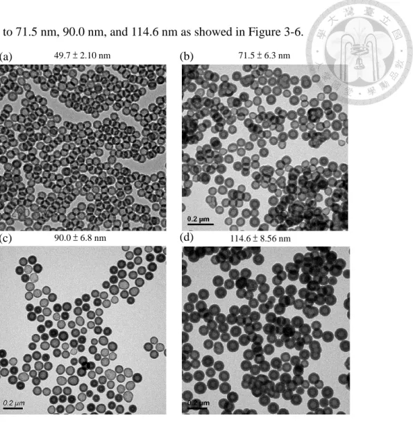
Figure 3-6. The TEM images of HSNs from M2S5 system with (a) 125 uL, (b) 250
uL, (c) 400 uL, (d) 500 uL of ethanol. ... 44
Figure 3-7. The DLS measurement of bare SSNs and HSNs in D.I water. ... 45
Figure 3-8. Effects of pH value on the silica condensation rate, charge properties and charge density on the surface of the silica species. 41 ... 46
Figure 3-9. The TEM images of bare HSNs from open synthetic system. ... 47
Figure 3-10. The DLS measurement of (a) SSNs and (b, c) HSNs in different solvent from open synthetic system. ... 48
Figure 3-11. The DLS measurement of HSNs with post-modification of PEG. ... 48
Figure 3-12. (a) TEM image of PEG-HSNs. ... 49
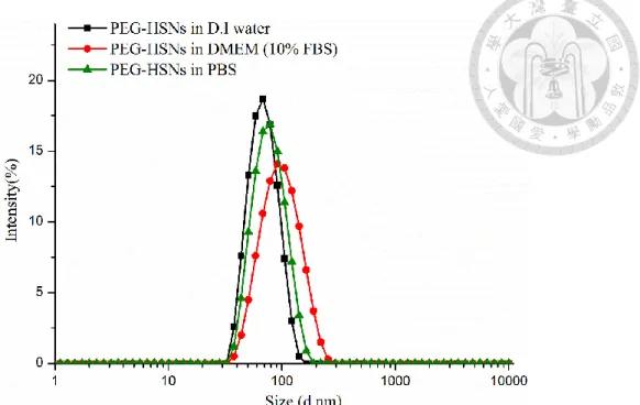
Figure 3-13. The DLS measurement of PEG-HNSs in different solvents. ... 50
Figure 3-14. Schematic illustration of synthesizing the multi-shelled HSNs. ... 51
Figure 3-15. The TEM images of double-shelled HSNs from M2S2S6 system. The particle size is 60 ± 3.9 nm, inter-shell space is about 4.6 nm and the size of inner HSNs is 37.1 ± 4.0 nm. ... 52
Figure 3-16. The N2 adsorption-desorption analysis of (a) double-shelled HSNs from M2S2S6 system, and (b) HSNs from M2S5 system. ... 52
Figure 3-17. The TEM images of triple-shelled HSNs from M2S2S6S18 system. The particle size is 78.9 ± 4.90 nm. ... 53
Figure 3-18. The TEM images and structure description of the double-shelled HSNs from (a)M2S2S6, (b)M2S2S10, (c)M2S2S15, and (d)M2S2S20 system. ... 54
Figure 3-19. Schematic illustration of liposomal doxorubicin and PEG-HSNs. ... 56
Figure 3-20. Schematic illustration of two-phase Dox loading system on PEG- HSNs...……… ... ..57
Figure 3-21. The photos of loading process. (a)before loading, (b)after loading, and (c) supernatant and pellet after centrifugation. ... 58
Figure 3-22. TEM images and schematic illustrations of the Dox@PEG-HSNs in (a) CHCl3 and (b) additional (NH4)2SO4 (pH=7.4). ... 59
Figure 3-23. Solubility of Dox in different salt solutions as a function of pH value………… ... 60
Figure 3-24. The TEM images of Dox@PEG-HSNs after treated with (a) (NH4)2HPO4 (aq) (pH 8.4), and further with (b) (NH4)2SO4 (aq) (pH 8.4). (c) The photos of Dox@PEG- HSNs in PBS without drug leakage in the supernatant. ... 60
Figure 3-25. The schematic illustration of the proposed mechanism of blocking the drug leakage by (NH4)2HPO4 (aq) (pH 8.4) treatment... 61
Figure 3-26. The TEM images of Dox@PEG-HSNs from drug loading at different temperatures. (a) 40 °C (b) 50 °C (c) 60 °C. ... 63
Figure 3-27. The photos of the loading results with different pH value of (NH4)2SO4. (a) pH 3.8. (b) pH 5.5. ... 64
Figure 3-28. The DLS measurement of Dox@PEG-HSNs in PBS. ... 66 Figure 3-29. The DLS measurement of (a) Dox@PEG-HSNs and (b) Dox@PEG-TA HSNs after post-modification. And the zeta-potential of (c) Dox@PEG-HSNs and (c) Dox@PEG-TA HSNs after post-modification. ... 67 Figure 3-30. The Dox release profiles at different pH environment. (a) Dox@PEG-
HSNs. (b) Dox@PEG-TA HSNs. ... 69 Figure 3-31. TEM images of Dox@PEG-HSNs at different time during the drug release.
(a) 6 h and (b) 30 h, in pH 7.4. (c) 6h and (d) 30 h, in pH 5.5. ... 69 Figure 3-32. The cellular uptake efficiency of PEG-HSNs and PEG-TA HSNs by MDA-MB-231 cells after 4 hours incubation... 71 Figure 3-33. (a) The cytotoxicity analysis of PEG-TA HSNs, Dox@PEG-TA HSNs, and free Dox via WST-1 assay. (b) The images of MDA-MB-231 cells treated with PEG-TA HSNs, Dox@PEG-TA HSNs, and free Dox. ... 72 Figure 3-34. The confocal laser scanning microscopy images of MDA-MB-231 treated with (a) free dox and (b) Dox@PEG-TA HSNs (Dose: 8 ug/mL of Dox) for 24 hours. ……….. ... 74 Figure 3-35. Cell cycle analysis of MDA-MB-231 cells after 24 h treatments with (a) culture medium, (b) PEG-TA HSNs (100 ug/mL), (c)free Dox (8 ug/mL), (d) Dox@PEG-TA HSNs (Dox:8 ug/mL). (c) The cell cycle analysis represented in percentages. … ... 75 Figure 3-36. Western blot for the level of p-p38. ... 75 Figure 3-37. In vivo two-photon microscopy images of PEG-HSNs and PEG-TA HSNs in blood vessels. ... 77 Figure 3-38. The IVIS images of important organs taken from ICR nude mice with intravenously injection of PEG HSNs and PEG-TA HSNs after (a) 4 h, (b) 24 h... 78 Figure 3-39. The IVIS images of PEG HSNs (RITC conjugated) in tumor-bearing mice after 4 h and 24 h intravenously injection. ... 79 Figure 3-40. The IVIS images of PEG HSNs (RITC conjugated) in important organs and tumor from tumor-bearing mice after 24 h intravenously injection. ... 79
List of Tables
Different synthetic systems with various ratios of microemulsion and silica sources……….. ... 24 Different synthetic microemulsion systems for double-shelled HSNs. ... 28 The size, yield, size distribution, and TEM images of HSNs from M1S1, M1S5, M2S5, M5S5 systems by time-separated addition of 5 times of silica source. ……….. ... ..42 The relation between the amount of Dox used and the concentration of (NH4)2SO4 on the loading capacity (L.C) and the entrapment efficiency (E.E) ... 65 The optimized doxorubicn loading condition for further studies. ... 66
Chapter 1 Introduction
1.1 General introduction of hollow silica nanospheres
Hollow silica nanospheres (HSNs), as a kind of porous silica-based nanomaterials, have attracted increasingly attention recently. Different form common mesoporous silica nanoparticles (MSNs), HSNs can encapsulate species with large size and increase the loading capacity of active agents due to its unique morphology with the thin porous shell and hollow interior voids, which enhanced the efficacy of applications no matter in catalysis or biomedicine1. The morphology and characters of HSNs greatly depend on the synthetic strategies which also make differences in various applications. Several strategies have been developed for fabricating hollow silica nanoparticles. Most of approaches can be generally classified into hard-templating method, soft-templating method, and structural-difference selectively etching method based on the way for constructing the hollow space 1-4. Herein, we will briefly discuss the basic concepts and some examples for these methods.
1.1.1 Hard-templating method
In hard-templating method as a conventional method, a heterogeneous solid rigid particles are generally used as a core template for the formation of silica shell, and the core templates need to be removed by calcine or solvent extraction to construct the hollow space, as shown in Figure 1-1 1,5.
Figure 1-1. Schematic illustration of hard-templating method. 5
The polymer latex such as polystyrene (PS) nanoparticles were usually used as a template due to its uniform size and adjustable properties 4. For example, Xia et al.6 have successfully prepared hollow silica spheres via polystyrene beads as a hard template which can be removed by calcine or dissolution with toluene. Furthermore, Giannelis et al.7 have reported a facile and scalable method to synthesize monodisperse mesoporous hollow silica nanospheres (mHSNs) with a relatively concentrated polystyrene latex templates. The particle size of mHSNs can be tuned from 100 nm to micrometers (Figures 1-2). Beside the polymer latex template, inorganic nanoparticles can also act as a core template for HSNs.
Figure 1-2. Representive TEM images of monodispersed mHSNs: (a) 140 nm mHSNs;
(b) 400 nm mHSNs; (c) 1500 nm mHSNs. 7
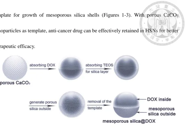
Recently, Zhao et al. 8 have developed a preloaded anti-cancer drugs in HSNs via porous CaCO3 nanoparticles as templates. The doxorubicin preloaded porous CaCO3
nanoparticles(100 nm) which can be removed in weakly acid solution can act as a hard-
a b c
template for growth of mesoporous silica shells (Figures 1-3). With porous CaCO3
nanoparticles as template, anti-cancer drug can be effectively retained in HSNs for better therapeutic efficacy.
Figure 1-3. The schematic illustration of doxorubicin preloaded mesoporous silica nanospheres by CaCO3 nanoparticles templating. 8
By hard-templating method, the size control of HSNs can be achieved easily. The shape and dimension of the cavity are the same as the template used. However, it require a multistep synthetic process as well as a tedious template removal process which is time- consuming and complicated 4.
1.1.2 Soft-templating method
In soft-templating method, the core templates can be heterogeneous flexible liquid particles, such as micelles, emulsion 9,10, vesicles 11,12, or gas bubbles. For micelle- templating method, Yang and co-workers13 have synthesized small hollow organolsilica nanospheres with 20 nm size through the condensation of 1,2 bis(trimethoxysilyl)ethane
(BTSE) around an inorganic-electrolyte-stabilized F127 micelle under a mild buffer condition. Moreover, Zhao and coworkers 14 have developed a one-step soft-templating approach for synthesizing shape-tunable hollow silica nanomaterials, including nanowire, nanospheres, and nanotadpole by simply changing poly(vinylpyrrolidone) (PVP)−water droplets with three different solvents, including 1-propanol, 1-pentanol, and ethanol, led to the designed shapes. For emulsion-templating method, Kao et al. 9,10 used an oil in water emulsion system with CTAB to synthesize both mHSNs and Kippah-like mHSMs via interfacial hydrolysis/condensation on the surface of the emulsions. The special Kippah-like mHSNs formed if the oil in the O/W emulsion escape through mesopores before the silica shell become rigid, as shown in Figure 1-4.
Figure 1-4. The images of Kippah-like mHSMs by (a) SEM (b) TEM. (c) Schematic illustration of the proposed mechanism. 10
c
a b
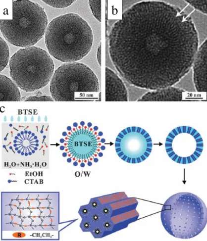
Recently, Ma et al. 15 develop a simple and effective method to synthesize hollow periodic mesoporous organosilica nanospheres (HPMOSs) by using O/W microemulsion with organosilane (BTSE) as oil core in presence of CTAB. The BTSE of the oil droplets were hydrolyzed and condensed around the oil–water interface under the catalysis of ammonium. Meanwhile, the ordered mesochannels were formed in the shells due to the CTAB templating. As the reaction goes, the BTSE on the interface were consumed continuously, and the BTSE in the oil core diffused continuously to the interface, leaving behind hollow cores, as shown in Figure 1-5.
Figure 1-5. The TEM images (a, b) of HPMOSs by O/W microemulsion with BTSE as oil core. (c) Schematic illustration of the proposed mechanism. 15
a b
c
Recently, soft template method is popular due to the easy preparation and removal of soft templates. However, it is generally considered that HSNs prepared by this method shows irregular appearance and wide particle size distribution due to the flexibility of soft template. But now these defects have basically been overcome with continuous efforts of many researchers 4.
1.1.3 Structural-difference selectively etching method
In the structural-difference selectively etching method, the hollow structure can be constructed by selectively etching the fragile part of the nanoparticles with inherent or designed silica-based structural difference. Several literatures have demonstrated the inhomogeneous nature of outermost shell and inner layer on the silica nanospheres from general sol-gel process. Park et al.16 have found that the solid silica nanospheres about 50 nm from microemulsion method would transform into hollow structure in mild basic water solution after 30 days. Also, Wong et al. 17 have provided the evidence for the inhomogeneity of silica shell from the Stöber method, and the yolk-shell and multi yolk- shell motives can be fabricated through hydrothermal treatment in 90 °C water bath. They have proposed that as the growth of silica layer on the gold nanoparticles, the outer silica layer was from the condensation of silicic acid and its aggregation so that the hardened layer. In comparison, the inner layer was from the lower degree of cross-linking and/or higher degree of solvent swelling, resulting in softer layer inside.
Furthermore, recently Zhao and coworkers 18 have synthesized the multi-shelled periodic mesoporous organosilica hollow spheres by hydrothermal treatment for the first time, also based on the concept of inhomogeneity of silica shell on silica nanoparticles, as shown in Figure 1-6.
Figure 1-6. Schematic illustration of the successive growth process of the organosilica/CTAB composite spheres in ammonia and ethanol solution and the corresponding multi-shelled products after the hydrothermal treatment. 18
The selective etching process could be relatively controllable and mild if the structural difference can be enhanced by suitable designation during the fabrication. Shi and coworkers19 have synthesized a novel a silica core/mesoporous silica shell nanospheres with structure structural differences, rather than traditional compositional differences. It was found that the condensation degree of the meosoporous shell is higher than that in the solid silica core, which was generated by the self-assembly between
C18TMS and TEOS. By etching process in Na2CO3 solution, the yolk-shell and hollow silica nanospheres can be synthesized. For smaller particle size, Mou and coworkers 20,21 have developed a microemulsion method to synthesize HSNs. Due to the incorporation of (3-Aminopropyl)trimethoxysilane (APTMS) with TEOS, solid silica nanospheres with structural difference can be etched to hollow through mild warm-water etching process, and the size of HSNs can be well-controlled by tunable microemulsion systems.
The structural-difference selective etching process without separately preparation of template is facile, effective, scalable, controllable, and cost-effective. It is convenient to tune the morphology of HSNs by suitable etching process, and a sufficient amount of particle samples can be provided for practical applications 3.
1.2 HSNs from microemulsion method
The hollow silica nanospheres from the microemuslion method have gained increasing interests because of the simplicity and versatile advantages of the unique synthesis method, as described in our previous reports 20-24. Herein, we will introduce the mechanism of HSNs from microemulsion method 21, advantages in bio-applications 22,23, and the challenges.
1.2.1 Mechanism of HSNs from microemulsion method
The water-in-oil W/O microemulsion, as a thermodynamically stable system, offers uniform and small water droplets as confined spaces for growth of silica nanoparticles
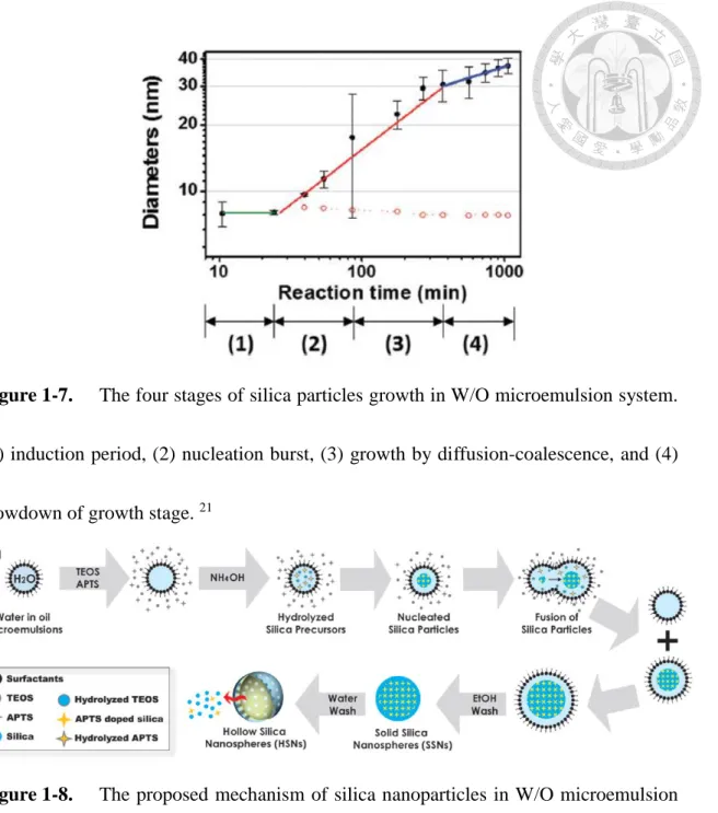
through a sol-gel reaction 20. There were four states of particles growth, as shown in Figure 1-7, including: (1) induction period, (2) nucleation burst, (3) growth by diffusion- coalescence, and (4) slowdown of growth stage. The initial droplets (∼8 nm) in the
reverse microemulsion are mainly water, and the hydrophobic silica source TEOS and APTMS are majorly dissolved in the oil phase. After NH4OH was introduced into the system, TEOS and APTMS would be hydrolyzed into silanol groups (Si–O− or Si–OH), which would move into the water droplets and condense into polymeric species. In this stage- the induction period for nucleation, there was no apparent change of particle size, which was not identified in typical Stöber process because it was much faster in homogeneous solution compared to our reverse microemulsion system. Next, as the nucleation burst period (~30 to 100 min), through inter-droplet collision/exchange, the polysilicate species could initiate the nucleation of silica nanoparticles, and further growth of the surfactant-stabilized nuclei occurred through inter-droplet coalescence.
After that, the nucleation was quenched, and growth by diffusion/coalescence dominated (~100 to 400 min). In the final stage, subsequent slowdown of growth process became size-focusing and reducing size variance, which is unlike the Ostwald Ripening in most of synthesis of nanoparticles. This makes the reverse microemulsion method advantageous in size uniformity. The overall proposed mechanism was shown in Figure 1-8.
Figure 1-7. The four stages of silica particles growth in W/O microemulsion system.
(1) induction period, (2) nucleation burst, (3) growth by diffusion-coalescence, and (4) slowdown of growth stage. 21
Figure 1-8. The proposed mechanism of silica nanoparticles in W/O microemulsion system. 21
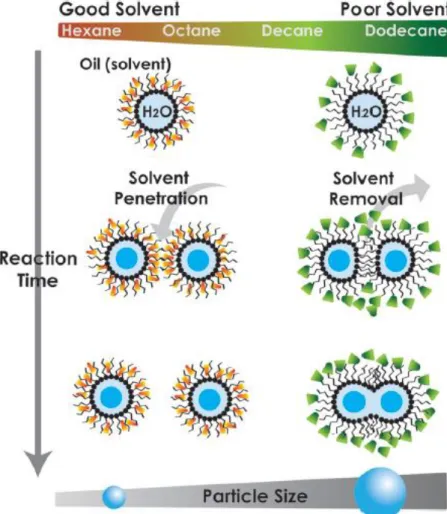
The particles size also can be effectively controlled by adjusting the composition of microemulsion, such as the alkane chains of continuous oil phase, amount of co- surfactant and mixture ratio of surfactants. In the system with shorter alkanes as oil phase, the smaller particles will be attained due to a stronger entropic repulsion between two approaching micelles, which protects the interface from fusion and coalescence. With
more amount of co-surfactant such as n-hexanol, the larger particles will be synthesized due to the increasing flexibility of surfactant film resulting in the increasing fusion dynamics of micelle. The composition of the microemulsion would alter the diffusive coalescence kinetics of micellar droplets which dominates the growth process and final particle diameters, as shown in Figure 1-9.
Figure 1-9. Schematic illustration of solvent-initiated fusion pathways for silica nanoparticle formation. 21
1.2.2 Advantages and challenges in bio-applications
With small and tunable size, HSNs show tremendous potentials in biological applications. By taking advantages of synthesis in microemulsion system, Chang et al.
22,23 have developed a de novo enzyme encapsulation in HSNs and nicely solved the ship-
in-bottle problem by microemulsion method. The superoxide dismutase (SOD) and catalase (CAT) enzymes could be prepared in water phase of microemulsion and simultaneously encapsulated during the particle growth in water droplets. Due to the incorporation of APTMS, the mild selectively etching process could be carried on in 40
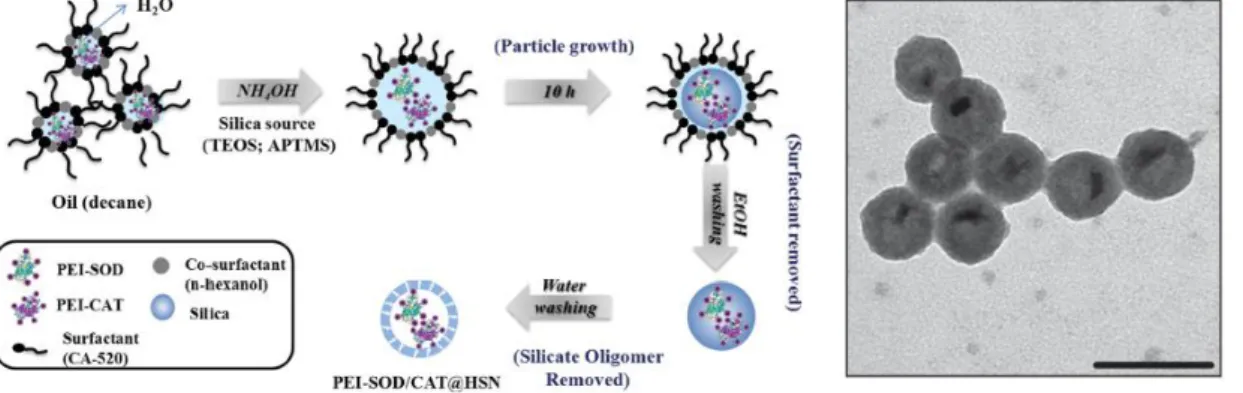
°C warm water which is important to retain the activity of enzyme, as shown in Figure 1- 10. With the protection and permeability of silica shell, PEI-SOD/CAT@HSNs showed an enhanced intracellular activity and excellent biocompatibility in living cell. These results greatly demonstrate the novel HSNs from microemulsion can display outstanding performance in biological applications.
Figure 1-10. (a)Schematic illustration of encapsulation of enzyme during synthesis of
HSNs by microemulsion method. (b) The TEM images of PEI-SOD/CAT@HSNs.23
(a) (b)
However, for a practical bio-applications as commercial products, the HSNs may be largely restricted by the problem of low production yield (10mg/ 20 mL oil) and easy- aggregation. Therefore, further study on the optimization of HSNs from microemulsion method should be inevitable.
1.3 Hollow silica nanospheres in anti-cancer therapy
1.3.1 General introduction
Nanomedicine is defined as the medical applications of nanotechnology, integrating the knowledges from multiple fields of nanotechnology, chemistry, medicine and material science 25. The anti-cancer nanomedicine is one of the most important research field because the cancer is one of the deadliest killer to human beings. In typical cancer therapy, the poisonous chemotherapeutic drugs are generally used to treat the cancer cell, but the toxicity of drugs also damages the normal cell and may cause the life-threatening side effects. Therefore, several researchers devote to explore a nano-carrier as an excellent drug delivery system (DDS) to overcome the problems. Several organic nano-carriers have been developed to clinical tests, and few of them have been approved by U.S Food and Drug Administration (FDA), such as the Doxil® (PEG-liposomal doxorubicin) 26. On the other hand, the inorganic nano-carriers are still in preclinical stages and basic research, however, silica nanoparticles (Cornell Dot) have received FDA approval for clinical trials
27. Therefore, the silica-based nanoparticles display promising potentials as drug delivery
systems.
1.3.2 Hollow silica nanoparticles as drug delivery systems (DDSs)
Among several silica nanomaterials, the hollow silica nanospheres have gained increasing potentials as drug delivery systems due to their unique properties such as low density, large surface area, high loading capacity, rich surface chemical properties, and excellent biocompatibility 28. As an effective and efficient DDSs, several properties need to be incorporated into a designed nano-carrier, including 29: (1)Highly biocompatibility of the nano-carrier. (2)High loading capacity and entrapment efficiency of the therapeutic drugs. (3)Zero premature release of drugs before reaching the tumor sites. (4)Controlled release of drugs with a proper rate. (5)Cell type or tissue specificity and site directing ability to achieve an effective local concentration. Various strategies based on chemistry and biology usually are integrated to design a HSNs to match the requirements described above.
Lu and co-worker 30 combined a hydrophobic fluorescent hollow mesoporous silica nanoparticle (HMS NP) as the core and multifunctional amphiphilic agents as the capping shell. The hydrophobic fluorescent HMS NP could provide an excellent drug-loading capacity (15.8 wt %) and drug release profile. The amphiphilic capping agent consisting of four functional motifs: a targeting segment (folic acid), a hydrophilic segment, a pH- labile linkage, and a hydrophobic segment. These properties were then independently
integrated into a single nano-carrier to achieve efficient and targeted drug delivery. Wu et al.28 recently synthesize an organic-inorganic HMS nanoparticles with large pores (24 nm) to co-encapsulate the P-glycoprotein (P-gp) modulator siRNA and anti-cancer doxorubicin, and the surface of the nano-carrier was modified with poly(β-amino esters) via redox-responsive disulfide linker. The synergistic effect, including nano-carrier’s protection for siRNA from biodegradation, RNAi functioning for down-regulating overexpressed P-gp in drug resistant cancer cells and anticancer effect by Dox, can be achieved by concurrent transportation and selective releasing in intracellular reducing environment via a smart-designed nano-carrier.
Therefore, to develop an excellent drug delivery system, the nano-carrier should be intrinsically biocompatible, and the surface properties could be designed for tumor-site directing, long circulation and/or responsive release of drugs. For improvement of the circulation time, surface modification of PEG chain is usually adapted to stealth the active silica nanoparticles from inter-particle aggregation and protein adsorption 31. Moreover, development of an efficiency drug-loading method also is an important point that may reflect the utilization of drugs and the local concentration of drugs at the target.
1.3.3 Lesson to learn: The first FDA-approved nano-drug
By taking advantages of advanced nanotechnology, the cancer therapy could be more effective and efficiency, however, there are still little nano-drugs commonly used in
clinical treatment. Doxil® is the first FDA-approved nano-drug which is composed of the PEGylated nano-liposomes with high Tm (53 °C) and stable loaded doxorubicin gel/crystal 26, as shown in Figure 1-11. The concepts and success of the Doxil® are worthy to learn for development of a brand new nano-drug in the future. Herein, we will introduce two key points of the Doxil®, including the nano-carrier designation and the special drug loading method.
Figure 1-11. (a) A cartoon of Doxil®=PEGylated nano (< 100 nm) unilamellar liposome. (b) Cryo-TEM images of commercial Doxil®. 26
1.3.3.1 Liposome design
The failure of the first generation of liposomal doxorubicin (OLV-DOX, oligolamellar liposomes) at 1980s’ could be attributed to the fast clearance of 200-500 nm negatively fluid liposomes from circulating by RES (reticuloendothelial system)32. To address the problem, series sterically-stabilized liposomes were developed by introducing the PEG moieties such as PEG-DSPE (2000 Da polyethylene glycol-
(a) (b)
disteroylphosphoethanolamine), as shown in Figure 1-12. With PEG stabilization, the small unilamellar liposomes with uniform size (~100 nm) could be attained, and the non- specific protein interaction could be reduced, leading the RES avoidance 33,34. With small size and prolonged circulation, Doxil® could take advantages of EPR (enhanced permeability and retention) effect and extravasate from the blood vessels at the tumor into the tumor tissue, demonstrating high and selective tumor localization. The data are the first proof for the EPR effect induced in tumor vasculature by passive targeting in humans34. Therefore, from the nano-carrier designation of the Doxil®, for the passive targeting, the nano-carrier should display a long circulation time (RES avoidance) and sustain the intact form during the circulation in the human plasma until reaching the tumor site.
Figure 1-12. A cartoon showing a comparison between a conventional liposome (left)
and a sterically stabilized (PEGylated) liposome (right). 26
1.3.3.2 Remote loading of doxorubicin
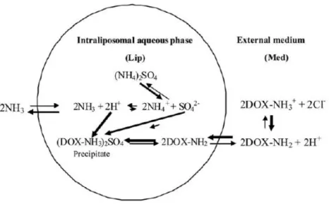
Another important challenge is to achieve the high therapeutic efficacy of the doxorubicin at tumor site (routine treatment by i.v. doxorubicin is 10 to 50 mg/m2 34) which was especially difficult for a small 100 nm liposome to deliver large amount of doxorubicin 26. Therefore, a sufficient level and high stability of drug loading for delivery should be achieved by a novel loading method instead of generally passive loading. The research group developed a remote loading method based on a transmembrane gradient of ammonium sulfate: [(NH4)2SO4]liposome≫[(NH4)2SO4]medium that acts as the driving force for the efficient and stable remote loading of amphipathic weak bases into preformed nano-liposomes 35-37, as shown in Figure 1-13.
Figure 1-13. Schematic illustration of remote doxorubicin loading into PEG-liposomes
exhibiting a transmembrane ammonium ion gradient. 26
The gradient of ammonium sulfate was generally established via hydrating the lipid
film with 250-300 mM (NH4)2SO4 buffer (pH=7.4), and the extra-liposomal buffer was exchanged through different buffers by size exclusion chromatography 35. Due to the large difference in thepermeability coefficients through lipid bilayers of thevarious species as (NH4)2SO4 < SO42- < NH4+<< H+<<< NH3 38, the high permeability coefficient of NH3
(1.3x10 -1 cm/s) lead to fast diffusion to the extra-liposomal medium. As every NH3
molecule leaving the liposome, one proton was left behind, forming a pH gradient in which the inside of the liposome became more acidic than the external medium. The extra-liposome medium was replaced with the doxorubicin solution, and the mixture was incubated in 40-60℃ for loading for at least 30 min. As the unprotonated Dox crossed
the liposomal membrane, it would be protonated and precipitate with negatively SO42-
into rod-like gel/crystal, thus concentrating and tapping Dox within the liposome. By the remote loading, > 90% of doxorubicin was encapsulated and in stable gel/crystal form.
Using doxorubicin remote loaded PEGylated nano-liposomes (Doxil® ) enabled achieving a doxorubicin circulation half-life time in humans of ~90 h and doxorubicin presence in the human circulation of >350 h 39. The Doxil® 's successful development opened the way to major improvement in tumor therapy and it served as a gold standard in the new field referred to as nano-medicine26.
1.4 Motivation and objectives
Due to the increasingly potentials of hollow silica nanospheres as drug delivery systems (DDSs) in cancer therapy, development of a well-controlled system to fabricate HSNs with desired properties is demanding no matter in basic researches or clinical use.
Several strategies for synthesis of HSNs were introduced in section 1.1. The microemulsion method developed in our group can effectively make monodispersed HSNs and control the particle size below 100 nm which is suitable for biomedical applications40. However, their applications were usually limited due to the low yield and easy-aggregation problem. Hence, we started from the material view to solve the problems based on the growth mechanism and silica chemistry.
Furthermore as an excellent DDS, the loading capacity and stability of therapeutic agents in nanocarriers usually dominates the anti-cancer efficacy. However, in most of literatures the passive loading method were usually applied to load anti-cancer drugs in silica nanoparticles which is not economic and efficient. Inspired by the success of Doxil®, we tried to establish an active loading method on hollow silica nanospheres to make good use of their unique morphology such as large interior space. Also, the in vitro and in vivo behaviors of HSNs, such as biocompatibility, circulation, and bio-distribution are also interesting and crucial for us to screen and design a suitable carrier. Based on investigating the silica nanotechnology, we aimed to improve the therapeutic efficacy of breast cancer,
one of deadliest killer for human beings. Overall, we tried to develop a well-controlled system for synthesis of HSNs with desired properties and an effectively active drug loading method, and further studied their in vitro and in vivo behaviors in order to create a new platform of nano-drug based on hollow silica nanospheres.
Chapter 2 Experimental section
2.1 Materials and methods
2.1.1 Materials
All reagents were used as received without further purification. Decane, hexyl alcohol (98%), ammonium hydroxide (NH4OH, 28~30 wt % NH3), tetraethylorthosilicate (TEOS, 98%), 3-aminopropyltrimethoxysilane (APTMS, 95%), fluorescein isothiocyanate (FITC, 90%), ammonium dihydrogen phosphate (98%), chloroform (99%), D (+)-sucrose (99%) were purchased from Acros. Polyoxyethylene (5) nonylphenyl ether, branched (Igepal CO-520, NP-5), Rhodamine B isothiocyanate (RITC, 70%), ammonium sulfate (for molecular biology, 99%), doxorubicin hydrochloride (98%) was purchased from Sigma Aldrich. Ethanol (99.5%) was purchased from Fisher Scientific. N- trimethoxylsilypropyl-N,N,N-trimrthylammonium chloride (TMAC-silane, 50%), 2- [methoxy(polyetheyleneoxy)propyl]-trimethoxysilane (PEG-silane, 90%) were purchased from GELEST. Ultrapure deionized (D.I.) water was generated using a Millipore Milli-Q plus system.
2.1.2 Characterization
TEM imgas were performed on a Hitachi H-7100 transmission electron microscope opereated at accelerated voltages of 75 KV. Sample dispersed in ethanol were sonicated
for 30 seconds before depositing on a carbon-coated Cu grids and dried in air. N2 adsorption-desorption isotherm were measured at liquid N2 temperature (-196 °C) on a Micrometerics ASAP2010 apparatus. The samples were degassed at 100 °C overnight under 10-3 torr before measurement. The total surface area of sample was calculated based on Brunauer-Emmett-Teller (BET) method. UV-visible (UV-vis) spectra were measured using a Hitachi U3310 spectrometer from 300 nm to 600 nm. The dynamic light scattering (DLS) and zeta potential analysis of the samples was measured by MALVERN Nana-ZS Instruments equipped with a laser particle analyzer LPA-3100 at 25 °C. The concentration
of the nanoparticles was 0.2~0.3 mg/mL. The particle size was analyzed in different solvents, H2O (pH 6~7), Dulbecco’s Modified Eagle Medium (DMEM) with 10% FBS,
and PBS buffer solution (pH7.4).
2.2 Synthetic procedure
2.2.1 Synthesis and engineering of hollow silica nanospheres(HSNs)
2.2.1.1 Preparation of various synthetic microemulsion systems
Synthetic microemulsion system for hollow silica nanospheres was composed of decane as oil, CO-520 as surfactant, hexyl alcohol as co-surfactant, D.I water as aqueous phase, and silica source including APTMS and TEOS. Different synthetic systems with various ratios of microemulsion and silica sources were listed in the Table 2-1. In constant decane (20 mL), amounts of CO-520, hexyl alcohol, and D.I water were simultaneously
elevated in constant ratio to make microemulsion M1 (original system), M2, and M5.
Amounts of silica source were also adjusted to make S1 (original system) and S5.
Different synthetic systems with various ratios of microemulsion and silica sources.
2.2.1.2 Synthesis of hollow silica nanospheres (HSNs) by microemulsion method
The M2S5 system was chosen as the modal system for illustration. First, 20 mL decane as oil, 3.5 mL CO-520 as surfactant, 1.1 mL hexyl alcohol as co-surfactant, and 700 μL D.I. water were mixed to generate the reverse microemulsion system. Then, part
of silica source, 200uL of TEOS, was added into the system and kept stirring at 20°C.
Fifty minutes later, 500 uL of aqueous ammonia (28-30 wt %) was slowly introduced into the mixture to initiate the hydrolysis of TEOS. After 12 minutes, 125 uL of APTMS ethanolic solution (200 uL APTMS / 1.4 mL ethanol) and 300 uL of TEOS were slowly added into the mixture, and the mixture was stirred at 20 °C for 12 hours.
Systems M1S1 M1S5 M2S5 M5S5
Decane (mL) 20 mL
CO-520 (mL) 1.75 1.75 3.5 8.75
Hexyl alcohol (mL) 0.55 0.55 1.1 2.75
D.I water (mL) 0.35 0.35 0.70 1.75
TEOS (uL) 100 500 500 50
APTMS (uL) (in ethanol)
25 125 125 125
NH4OH (uL) 250 250 500 1250
Warm water used (mL) 40 200 200 200
The as-prepared solid silica nanospheres (SSNs) could be collected by adding 95%
ethanol to destabilize the microemulsion system and centrifugation at 15000 rpm for 25 minutes. The particles were washed by 95% ethanol three times, and further transferred into 200 mL D.I water. Then, the solution was kept in 50°C and stirred for 2 hours for the structural transformation of SSNs to HSNs. The HSNs were collected by centrifugation and washed with ethanol three times, and finally stored in 99.5% ethanol.
2.2.1.3 Synthesis of surface-modified HSNs
Surface modified HSNs could be synthesized in M2S5 system as described above with slight modification. The surface modifying agents accompanied with few TEOS (50 uL) were introduced into the growth solution to modify the as-prepared SSNs after aqueous ammonia had been added for 12 hours. The mixture was further stirred for 24 hours at 20 °C. The surface-modified SSNs were processed as the same way described above to remove the residues and underwent the warm water etching process resulting in the surface-modified HSNs. Different types and properties of the surface modifying agents for HSNs were listed in the Table.
2.2.1.4 Synthesis of HSNs under open system (M2S5)
Bare HSNs could also be synthesized under open M2S5 system. 20 mL decane, 3.5 mL CO-520, 1.1 mL hexyl alcohol, and 700 μL D.I. water were mixed to generate the reverse microemulsion. Then, part of silica source, 200uL of TEOS, was added into the
system and kept stirring at 20 °C. Fifty minutes later, 500 uL of aqueous ammonia (28- 30 wt %) was slowly introduced into the mixture to initiate the hydrolysis of TEOS. After 12 minutes, 125 uL of APTMS ethanolic solution (200 uL APTMS / 1.4 mL ethanol) and 300 uL of TEOS were slowly added into the mixture. After stirred for 5 min, the bottle was open and stopped stirring for the evaporation of NH4OHat 20 °C without disturbance for 72 hours.
The as-prepared bare solid silica nanospheres (SSNs) could be collected by adding 95% ethanol to destabilize the microemulsion system and centrifugation at 9000 rpm for 15 minutes. The particles were washed by 95% ethanol three times, and further transferred into 200 mL D.I water. Then, the solution was kept in 50 °C and stirred for 2 hours for the structural transformation of SSNs to HSNs. The HSNs were collected by centrifugation and washed with ethanol three times, and finally stored in 99.5% ethanol.
2.2.1.5 Synthesis of multi-shelled HSNs
Multi-shelled HSNs could be synthesized through layer-by-layer and one-step etching approach. The first inner spheres were synthesized under M2S2 system in which
silica source were 2/5 of M2S5 system. 20 mL decane, 3.5 mL CO-520, 1.1 mL hexyl alcohol, and 700 μL D.I. water were mixed to generate the reverse microemulsion. Then,
part of silica source, 80 uL of TEOS, was added into the system and kept stirring at 20℃.
Fifty minutes later, 500 uL of aqueous ammonia (28-30 wt %) was slowly introduced into
the mixture to initiate the hydrolysis of TEOS. After 12 minutes, 50 uL of APTMS ethanolic solution (200 uL APTMS / 1.4 mL ethanol) and 120 uL of TEOS were slowly added into the mixture. After formation of the first spheres, different amounts of silica source, listed in Table 2-2, was introduced to the mixture again to form the second silica layer on the first spheres, and further stirred for 12 hours. Surface-modifying agents PEG- silane (500uL) and of TEOS (50 uL) were added to modify the particles for 24 hours. The as-prepared SSNs were processed as the same way described above to remove the residues by EtOH washing. Then the particles were dispersed in 200 mL D.I water and stirred at 50 °C for 2 hours for the structural transformation. Double-shelled HSNs (DS- HSNs) were collected by centrifugation and washed with ethanol three times, and finally stored in 99.5% ethanol.
Different synthetic microemulsion systems for double-shelled HSNs.
2.2.2 Bio-applications of hollow silica nanospheres
2.2.2.1 Synthesis of PEG-FITC HSNs and RITC-HSNs
As an anticancer drug nanocarrier, long circulation time, trackable performance, and high loading capacity were essential properties. Hence, surface-modifying PEG-silane and organic fluorescent dye FITC were integrated into the HSNs synthesized in the M2S5 system.
The FITC or RITC conjugated APTMS (FITC-APTMS or RITC-APTMS) ethanolic solution was first prepared. 3 mg of FITC (or 12 mg of RITC) powder was dissolved completely in 1.4 mL 99.5% ethanol, then 200 uL of APTMS was introduced to conjugate with FITC or RITC through the covalent bond. The mixture was sealed and stirred in the dark room for at least 8 hours.
System M2S2S6 M2S2S10 M2S2S15 M2S2S20
1stsphere M2S2
Decane (mL) 20 mL
CO-520 (mL) 3.5
Hexyl alcohol (mL) 1.1
D.I water (mL) 0.70
TEOS (uL) 200
APTMS (uL) (in ethanol)
50
NH4OH (uL) 500
2ndsphere S6 S10 S15 S20
TEOS (uL) 600 1000 1500 2000
APTMS (uL) (in ethanol)
150 250 375 500
The hollow silica nanospheres were synthesized in the M2S5 microemulsion system.
First, 20 mL decane as oil, 3.5 mL CO-520 as surfactant, 1.1 mL hexyl alcohol as co- surfactant, and 700 μL D.I. water were mixed to generate the reverse microemulsion
system. Then, part of silica source, 200uL of TEOS, was added into the system and kept stirring at 20 °C. Fifty minutes later, 500 uL of aqueous ammonia (28-30 wt %) was slowly introduced into the mixture to initiate the hydrolysis of TEOS. Further 12 min later, 125 uL of FTIC-APTMS ethanolic solution and 300 uL of TEOS were slowly added into the mixture, and the mixture was stirred for 12 hours at 20℃.Then, surface-modification
PEG-silane accompanied with few TEOS (50 uL) were introduced into the system to modify the as-prepared solid silica nanospheres (SSNs) and further stirred for 24 hours.
The PEG-modified SSNs (PEG-SSNs) could be collected by adding 95% ethanol to destabilize the microemulsion system and centrifugation at 15000 rpm for 25 minutes.The PEG-FITC SSNs were washed by ethanol three times, and further transferred into 200 mL D.I water. Then, the solution was kept in 50 °C and stirred for 2 hours for the structural transformation of SSNs to HSNs. The PEG-FITC HSNs were collected by centrifugation and washed with ethanol three times, and finally stored in 99.5% ethanol.
2.2.2.2 Loading doxorubicin (Dox)
The anticancer drug doxorubicin (Dox) was loaded into PEG- HSNs or PEG-FITC HSNs through a solubility-triggered loading method in two-phase system (H2O/CHCl3).
First, 3 mg PEG-HSNs were dispersed in 300 uL of (NH4)2SO4 solutions with different concentrations, and the solution was shaken for 30 min for the diffusion of (NH4)2SO4 into the particles through the porous shell. Then, by centrifugation at 15000 rpm for 10 min, (NH4)2SO4@PEGylated HSNs were collected in pellet form, and the pellet was covered by 250 uL of chloroform, which could block the diffusion of aqueous (NH4)2SO4 out from the particles, and mixture was stirred slowly for fully dispersion of (NH4)2SO4@PEG-HSNs in CHCl3. After that, pH 8.2 sucrose aqueous solution (10 wt %) including doxorubicin was introduced and covered on the organic chloroform layer.
The mixture with two distinct phases was stirred for 2 hours at 50 °C for the phase transfer of Dox from upper aqueous layer to lower organic phase. The Dox loaded particles were collected by centrifugation at 15000 rpm for 15 min. The Dox@PEG HSNs were dispersed in 100 uL of 500mM (NH4)2HPO4 (pH 8.4). Surface-modifying agents such as PEG-silane (10 uL), TMAC-silane (2 uL) and TEOS (5 uL) were added to the mixture, and the mixture was stirred for 12 hours. After post-modification, Dox loaded particles were collected by centrifugation, and 100 uL of 500mM (NH4)2SO4 (pH 8.4) was added to make Dox gelation. Then, the particles were washed and stored in PBS for further characterization.
2.2.2.3 Loading capacity and entrapment efficiency
The loading capacity of Dox loaded HSNs with different modification were
determined by the absorbance of doxorubicin at wavelength 485 nm by UV-Vis spectrometry. The baseline was measured in the 1 mg/mL of PEG-HSNs PBS solution, and the calibration curve was prepared by dissolving different amount of Dox in 1 mg/mL of PEG-HSNs PBS solution, including 20, 40, 60, 80, 100 Dox ug/mL. The Dox loaded particles (~3 mg) were first dispersed in 600 uL of PBS, and 200 uL of the solution (about 1 mg of particles) was diluted to 1 mL by addition of 800 uL of fresh PBS for UV-Vis measurement. After measurement, the Dox loaded particles were collected in pellet and dried in oven at 60°C for weighing. The loading capacity was calculated by the equation
(2.1), and the entrapment efficiency was calculated from the equation (2.2).
Drug loading =mass of Dox loaded in particles
mass of Dox loaded particles (2.1) Drug loading = mass of Dox loaded in particles
mass of Dox initial used for loading (2.2) 2.2.2.4 Doxorubicin release study
For drug release study, 1.5 mg of Dox loaded particles were first dispersed in 2 mL PBS (pH 5.5 or 7.4) and taken in a dialysis device (Thermal Slide-A-LyzerTM MINI dialysis Device, 2mL, MWCO: 10 KDa). The dialysis tube with Dox loaded particles was introduced into a release medium containing 40 mL PBS solution (pH 5.5 or 7.4). The whole device was kept and stirred at 37 °C. The amounts of drug released was estimated from the measurement of the residual drug in the particles at each sample point by UV- Vis absorbance. At each point, sink condition was maintained by replacing 2 mL of the
release PBS with fresh PBS. The percent drug release was calculated by the equation (2.3).
%Drug release = (1- Absorbance (t)
Absorbance (to) ) (2.3) 2.2.2.5 Cellular uptake
The uptake efficiency of PEG-RITC HSNs and PEG-TA-FITC HSNs by MDA-MB- 231 cells was determined a FACS Calibur flow cytometer and Cell Quest Pro software (Becton Dickenson, Mississauga, CA). The green emitting fluorescein dye FITC incorporated in particles serves as a marker to quantitatively determine their cellular uptake. 2×10⁵ MDA-MB-231 cells were seeded in 6-well plates and allowed to attach overnight. Then, cells were incubated with 25, 50, 100, 250, 500, 750 μg/mL of particles in DMEM F12 medium for 4 h. Treated cells were then washed twice with PBS and then harvested by trypsinization. After centrifugation, the cells were dispersed in trypan blue solution to quench the fluorescence of particles adsorbed on the cell surface and flow cytometry analysis was carried out.
2.2.2.6 Cytotoxicity assay
The biocompatibility of particles and the cytotoxicity of free drugs and drug loaded particles were evaluated by WST-1 assay. 5×10³ MDA-MB-231 cells per well were seeded in 96-well plates for proliferation assays. The PEG-TA HSNs in medium with different particle concentration were incubated with cells for 24 hours (25, 50, 100, 250, 500, 750 μg/mL). To evaluate the anti-cancer efficacy of Dox@PEG-TA HSNs, the cells
were incubated with Dox@PEG-TA HSNs and the corresponding concentration of free Dox solutions in 2, 4, 8, 20, 40, 60 Dox ug/mL for comparison. After incubation for 24 hours, the cells were washed twice with culture medium followed by incubation with WST-1 reagent (Clontech) for 2 hours at 37 °C for proliferation assay. The formazan dye generated by the live cells was proportional to the number of live cells and the absorbance at 440 nm was measured using a microplate reader (Bio-Rad, model 680).
2.2.2.7 Confocal microscopic examination of intracellular drug release
The MDA-MB-231 cells were seeded on the glass overslipes at density of 2×10⁵ cell per well and cultured overnight. The cultured medium was replaced with Dox@PEG-TA- FITC HSNs (100 ug/mL) and incubated for 24 hours. After 24 hours, the MDA-MB-231 cells were fixed with 4% paraformaldehyde and permeabilized with 0.1% Triton X-100
for 5 minutes. After PBS washed, the cells were counterstained for nuclei with 4′,6- diamidino-2-phenylindole (DAPI, DNA marker) for 1 min and washed with PBS. The fluorescence images were obtained with a confocal laser scanning microscope (TCS SP8, Leica).
2.2.2.8 Cell cycle analysis
MDA-MB-231 cells were seeded at 2 × 10⁵cells per well in 6-well plates and allowed to attach for 24 h at 37 °C. Then, the PEG-TA HSNs (100 ug/mL), Dox@PEG- TA HSNs (8 Dox ug/mL) and fresh medium were incubated with the cells for 24 hours.
The cells were trypsinized, collected, and fixed with 70% precooled ethanol at 4 °C for 24 h. Fixed cells were washed twice with ice-cold PBS, incubated with 1 μg/mL RNase A for 20 min at 37 °C, and then stained with 10 μg/mL PI for 30 min in the dark. Stained MDA-MB-231 cells were analyzed by flow cytometry. Statistical analyses were performed using ModFit LT software (Verity Software House, Topsham, ME).
2.2.2.9 Western blotting analysis
Collected cell lysates were separated by 10 % SDS-PAGE and then transferred electrophoretically to a polyvinylidene difluoride (PVDF) membrane which was blocked in blocking buffer [1X Tris-buffered saline (TBS)- 0.1 % (v/v) Tween20, 5 % (w/v) non-
fat milk] for 1 h. The membrane was incubated with primary antibodies against p-p38 (Cell Signaling Technology; 1:500), α-tubulin (Santa Cruz; 1:10000) overnight at 4℃.
The PVDF membranes were extensively washed and incubated with secondary immunoglobulin G antibody (1:2000 dilution, Santa Cruz) for 1.5 h at room temperature.
Immunoreactive bands were visualized with the enhanced chemiluminescence substrate
kit (Amersham Pharmacia Biotech, GE Healthcare UK Ltd, Bucks, UK) according to the manufacturer’s protocol.
2.2.2.10 In vivo experiments
The Institute of Cancer Research (ICR) nude mice (8 weeks old) and tumor bearing mice (NOD.CB17-Prkdcscid/JNarl, 8 weeks old) were intravenously injected with PEG-
HSNs and PEG-TA HSNs (conjugated with RITC dye) at 200 mg/kg dose for each experiment.
2.2.2.10a Circulation
The circulation of particles in ICR nude mice was observed under two-photon microscopy, and the live-time images was acquired at 10, 30, 60, 120 min after injection.
To detect the vessels behind the ears, the hair on the ear needed to be removed for better detection.
2.2.2.10b Bio-distribution
To study the in vivo bio-distribution, the ICR nude mice was kept for 4 weeks, and the tumor-bearing mice (NOD.CB17-Prkdcscid/JNarl) (4 weeks old) was established by injecting with MDA-MB-231 tumor cells for 4weeks implantation. After the PBS solution of particles were intravenously injected, the major organs (heart, lung, spleen, liver, and kidney), urine and blood were carefully collected, and the fluorescence images of particles were acquired by using an IVIS Imaging System (Lumina) at indicated time (4 h and 24 h).
Chapter 3 Results and Discussion
3.1 Synthesis and engineering of hollow silica nanospheres
3.1.1 Yield improvement and size control of HSNs
As described in the introduction section, the applications of HSNs from microemulsion method were limited due to the problem of low production yield. Hence based on the growth theory of HSNs, the synthetic system with different compositions and silica source were systematically tried and studied for improvement of yield and size- uniformity.
3.1.1.1 Effects of the amount of silica source on HSNs (M1S1, M1S5)
Several microemulsion systems were studied for synthesis of hollow silica nanospheres in our previous reports 21,22. For improvement of the yield and uniformity, we primarily focused on the decane-CO 520 systems, which were composed of decane as oil, Igepal CO 520 as surfactant, hexyl alcohol as co-surfactant, and D.I water. In a synthetic system of HSNs, two kind of silica source including TEOS and APTMS would be hydrolyzed through NH4OH catalysis and condensed/nucleated through collision of the water droplets for growing the solid silica nanospheres (SSNs), then the SSNs could be transformed into hollow structure by warm-water etching process.
In original M1S1 system, the size of HSNs was about 40nm with a uniform size distribution, as shown in Figure 1-1a based on the TEM characterization. However, the