以PSS/PPY/碳纖維作為質子交換膜燃料電池觸媒載體之研究
On the PSS/PPY/Carbon fiber as catalyst support for polymer exchange membrane fuel cell 計畫編號:NSC-96-2221-E-006-130
執行期間:96 年 08 月 01 日 至 97 年 07 月 31 日 主持人:楊明長[email protected]
計畫參與人員:陸瑞東、陳美合、徐俊偉 國立成功大學 化學工程學系
計畫主持人在國科會工程處人才資料庫帳號: 0101003
摘要 Polymer electrolyte fuel cells (PEMFCs) have
been receiving interest on account of their attractive properties as a power source for stationary and vehicular applications. As PEMFCs require platinum (Pt) catalyst as an active material of electrode, one strategy is elevating catalytic activity by increase of the utilization of Pt in the catalytic via high dispersion of Pt nanoparticles. The dispersion of supported Pt is affected by synthesis method [1-4], and supported material [5-6]. In order to synthesize high-loading Pt catalysts with a narrow size distribution, surfactant is used as stabilizer [7-8]. Although the application of surfactants can provides well-dispersion Pt electrocatalysts, the removal of surfactant by thermal treatment makes Pt nanoparticle agglomerate. Generally, the preparing procedures of Pt catalysts involve the adsorption of metal precursor onto the carbon supports. Thus, the morphology and structure of carbon supports are considered major factor for high-dispersion Pt catalysts. Recently, Wu and coworkers [9] used a carbon black coated by graphitic layer that was carbonized from polyaniline as supports to prepare well-dispersed Pt catalysts (up to 60 wt%). The reason is that the graphitic layer shows nitrogen doping and a higher accessible surface area in electrochemical reactions. Sung and coworkers [13] investigateed the geometric effect of graphite nanofibers (GNFs) as a support of PtRu catalysts.
Its catalytic activity was higher than that of Vulcan XC-72 supported catalysts by 100%. Many researches focused on the functionlization of the carbon surface and pore structure [9-12]. The resulting materials gave more dispersive Pt nanoparticles than common carbon materials.
本研究利用有機合成方法將十二烷基胺修 飾在碳載體上,形成具疏水特性的載體,再以甲 醇還原法在此載體上製備出高分散性鉑釕奈米 粒子,做為質子交換模燃料電池觸媒。此具高分 散性鉑釕奈米粒子之觸媒在燃料電池之極化曲 線測試中,顯示對活性有明顯的提升。於實驗中 發 現 雖 然 陰 極 觸 媒 層 中 的 毆 姆 阻 抗 隨 著 PtRu/C(HN(CH2)11CH3) 觸媒的比例而提高,但整 體而言 PtRu/C(HN(CH2)11CH3) 觸媒的比例約在 20~40%可以獲得最好的效能,此混合式觸媒在陰 極電位0.6V 時,電池電流達 330 mA/cm2,高出 E-TEK 的觸媒約 44.7%。
關鍵字:質子交換膜燃料電池、觸媒單體、
疏水處理、膜電極組 Abstract
In this investigation, dodecylamine modified carbon supports with hydrophobic property were obtained by organic synthetic method based on an amide bond formation. The well-dispersed PtRu nanoparticle (@ 1~3nm) was obtained on the modified carbon supports as catalysts for polymer exchange membrane fuel cell by methanol reduction method. The well-dispersed Pt nanoparticles on the modified catalysts showed a significant enhancement on the cathode activity.
Although the ohmic resistance of the catalyst layer increased with the ratio of PtRu/C(HN(CH2)11CH3) in catalytic layer, the optimum ratio of PtRu/C(HN(CH2)11CH3) in catalytic layer was between 20% and 40%. Its cell current reached 330mA/cm2 at cathode potential of 0.6V, larger
than that with E-TEK electrode by 44.7%. In this work, uniformly dispersed PtRu nanoparticle was obtained by modifying carbon supports with dodecylamine using organic synthesis method.
The PtRu/dodecylamine-carbon catalysts in cathode electrode may provide a higher activity for polymer Keywords: PEMFC, carbon support,
hydrophobic treatment, MEA 1. Introduction
electrolyte fuel cells. The hydrophobic property of PtRu/dodecylamine- carbon was expected to supply the reactant gases and expel the produced water from the gas network [14].
2. Experiment
2-1. Surface modification of Carbon (Vulcan XC-72)
In order to clean the carbon surface, the raw carbon [Carbon(raw)] was pretreated in concentrated HCl (37% Scharlau) at 700C for 12hr [(Carbon(HCl)).
The raw carbon [Carbon(raw)] was modified by organic synthetic method based on the formation of an amide bond [15]. Purified carbon were stirred in concentrated HNO3 (65% Scharlau) at to form carboxyl group. Then the carboxyl- functionalized carbon was chlorinated by refluxing in SOCl2. After removal of the residual SOCl2 (Aldrich 98%) by distillation, the acyl chloride-functionalized carbon were reacted with excess dodecylamine (ACROS) in dehydrated toluene to obtain the desired C(HN(CH2)11CH3).
2-2. Electrocatalyst preparation
In order to prepare well-dispersed platinum colloids on the modified-carbons, impregnation method was applied with methanol reduction [16].
H2PtCl6 (ACROS), RuCl3 (Strem) and carbon supports were mixed in distilled water for 3hr.
The molar ratio of Pt and Ru was 1:1.
Subsequently, methanol was then added into the Pt-Ru solution for reduction. Afterward it was cooled, filtered, and then washed by distilled water several times. After drying, three kinds of electrocatalysts was obtained: PtRu/C (raw), PtRu/C(HN(CH2)11CH3) and PtRu/C(HCl).
2-3.
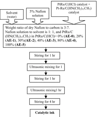
Preparation of 3E-MEAsThe standard catalytic ink was obtained by mixing Pt-Ru/C(raw) catalyst, Nafion solution (5%, Aldrich) and D.I. water at a carbon/Nafion (dry) ratio of 7:3 and a Nafion solution/water ratio of 1:1.
Different ratio of PtRu/C(HN(CH2)11CH3) and PtRu/C(HCl) catalysts were employed in the alternative catalytic ink. The ratio of carbon : Nafion : solvent was the same with the standard catalytic ink. The process of the catalytic ink is represented in Fig 1.
The standard electrode (SE-0) was prepared by
brushing the standard catalytic ink onto a wet-proofed carbon paper (Toray TGPH060). The preparing procedure for the alternative electrode (AE-1), (AE-2), (AE-3), (AE-4) and (AE-5) followed that for standard electrode by using alternative catalytic ink with 20%, 30%, 40%, 80%, 100% of PtRu/C(HN(CH2)11CH3) in PtRu/C(HCl) catalyst mixture. All electrodes were prepared with a Pt loading of 0.8 mg/cm2. The exposure area of the electrodes was 2.5 x 2.5 cm2.
PtRu/C(HCl) catalyst + Pt-Ru/C(HN(CH2)11CH3)
catalyst 5% Nafion
solution Solvent
(water)
Weight ratio of dry Nafion to carbon is 3:7.
Nafion solution to solvent is 1: 1, and PtRu/C (HN(CH2)11CH3) in PtRu/C(HCl)= 0% (AE-0), 20%
(AE-1), 30%(AE-2), 40% (AE-3), 80% (AE-4), 100% (AE-5)
Stiring for 1 hr
Ultrasonic mixing for 1 h
Stiring for 1 hr
Ultrasonic mixing1 hr
Stiring for 4 hr
Fig. 1. Fabrication procedure of the catalytic ink.
Catalytic ink
A platinum coating of 1.0 x 2.5 cm2 was deposited on a Nafion 117 membrane (Dupont) as a pseudo-reference electrode [17]. A three electrode membrane electrode assembly (3E-MEA) was made by hot pressing two prepared electrodes on the reference-deposited membrane at 1350C under 30 kg/cm2 for 1.5min.
2-4. Electrochemical characterizations
The 3E-MEA was installed as a single cell.
The reaction gases (hydrogen/oxygen) were fed to the cell at a flow rate of 100 ml/min. The cell temperature was held at 700C throughout the experiment. The gases for anode and cathode were held at 950C and 600C, respectively.
The polarization curves of the cell at steady state were collected using an electronic load (model 63010 from Chroma), and the anode and cathode polarization curves were measured against a pseudo-reference electrode using a multimeter (model 803 from Prova) at the same time.
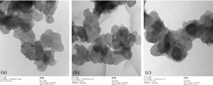
(a) (b) (c)
Fig. 2. TEM image of (a) PtRu/C(HN(CH2)11CH3), (b) PtRu/C(HCl) and (c) PtRu/C(raw).
2 theta
20 30 40 50 60 70 80
intensity
PtRu/C(raw) PtRu/C(HCl) PtRu/C(HN(CH2)11CH3)
Pt [111]
Pt
[200] Pt
[220]
0 20 40 60 80
1 2
3 4
5 6
Distribution(%)
Particle size (nm)
PtRu/C(HN(CH2)11CH3) PtRu/C(HCl treated) PtRu/C(raw)
Fig. 3. Size distributions of three kinds of electrocatalysts.
The particle sizes were evaluated from averaging TEM images.
Fig. 4. XRD of (a) PtRu/C(HN(CH2)11CH3), (b) PtRu/C(HCl) and (c) PtRu/C(raw)
catalysts.
3. Result and discussion
3-1. Characterization of electrocatalysts
3-2. Analysis of polarization curves
Fig. 5 shows the typical polarization curves of the cell (cathode vs. anode), cathode (vs. reference electrode) and anode (vs. reference electrode).
The cell potential is equal to be the potential difference between cathode and anode at a controlled current density. The experimental potential (E) and current density (i) were analyzed by tafel equation
Fig.2 shows typical TEM images of (a) PtRu/C(HN(CH2)11CH3), (b) PtRu/C(HCl) and (c) PtRu/C(raw). The average diameter of the metal nanoparticle was 1.86 nm on PtRu/C(HN (CH2)11CH3), 2.61 nm on PtRu/C(HCl) and 2.68 nm on PtRu/C(raw). The Pt particles on the surface of PtRu/C(HN(CH2)11CH3) shows the highest dispersion. The detailed size distribution is presented in Fig. 3. In PtRu/C(HN(CH2)11CH3) catalysts, the diameter distribution of Pt nanoparticles is in the range from 1 to 3 nm. Fig.
4 shows the XRD spectra of three kinds of
s
o
b i iR
E
E
= − log − 'where b, R′s and, Eo are Tafel slope, ohmic resistance of the cell and open circuit potential, respectively. It is assumed that mass transport limitation is negligible in above equation. On the cathode polarization curve, the rapidly decrease, below 30mA/cm2 was mainly due to
Current(mA/cm2)
0 200 400 600 800
Potential(v)
0.0 0.2 0.4 0.6 0.8 1.0 1.2
cathode:AE-0; anode:AE-0 cathode:AE-1; anode:AE-0 cathode:AE-2; anode:AE-0 cathode:AE-3; anode:AE-0 cathode:AE-4; anode:AE-0 cathode:AE-5; anode:AE-0
Cathode
Anode
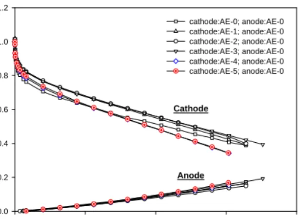
Fig. 6. Effect of the PtRu/C(HN(CH2)11CH3) content in the catalytic layer on cathode and anode polarization curves for AE-0, AE-1, AE-2, AE-3, AE-4 and AE-5 cathode electrodes. All anode electrode was AE-0. Pt loading was 0.8 mg/cm2. Key: (□) 0%; (△) 20%;
(○)30%; (▽)40%; (◇) 80%; (☉) 100%.
X Data
0 200 400 600 800
Y Data
-0.2 0.0 0.2 0.4 0.6 0.8 1.0 1.2
cell (cathode vs. anode) cathode vs. ref anode vs. ref fitting curve
Fig. 5. Polarization curves for cell and individual electrodes.
charge-transfer resistance. Above 50mA/cm2, the linear decrease was mainly due to the resistance of electrolyte between cathode and reference electrode. The behavior of cell polarization curve is similar to the cathode, because the anode charge-transfer overpotential was negligible and the resistance of the electrolyte between anode and reference electrodes was constant.
overpotential) for fuel cell system. The Tafel slope is 30.5 mV/decade for 20% PtRu/
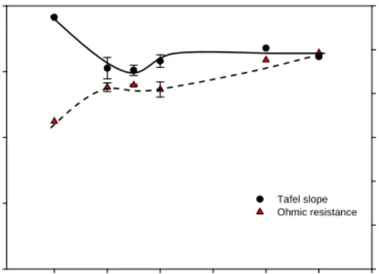
C(HN(CH2)11CH3), lower than 38.2 mV/decade for 0% PtRu/C(HN(CH2)11CH3). This enhanced activity of PtRu/C(HN(CH2)11CH3) was believed due to the increased surface area created by high dispersion. Fig. 8 illustrates the effect of PtRu/C (HN(CH2)11CH3) content in catalytic layer on Tafel slope and ohmic resistance. The PtRu/C (HN(CH2)11CH3) content in the range of 20-40%
gave a maximum activity. The ohmic resistance gradually increased with the increase of the PtRu/C(HN(CH2)11CH3) content. From those results dodecylamine group is expected to have higher ohmic resistance on electron transfer.
3-3. Effect of the PtRu/C(HN(CH2)11CH3) content in the catalytic layer on the polarization curves.
The polarization curve with the PtRu/C (HN(CH2)11CH3) content from 0 to 100 wt% in the cathode catalytic layer and PtRu/C(HCl) in the anode catalytic layer are shown in Fig. 6. In the cathode side, the best performance was obtained with the catalytic layer containing PtRu/C (HN(CH2)11CH3) between 20 and 40 wt%. When the content of PtRu/C(HN(CH2)11CH3) in the catalytic layer was 80%, the potential decreased sharply at current density higher than 30 mA/cm2. Possibly, it was due to that dodecylamine on the carbon surface had higher ohmic resistance. The phenomenon was also revealed in the polarization curve data of 0 wt% (AE-0). AE-0 electrode shows a rapid decrease at low current density and has a higher performance at low current density.
That means the carbon has lower ohmic resistance after cleaned with HCl. However, the dodecylamine-modified carbon shows higher ohmic resistance. The result was concluded in Fig. 7 and Fig. 8. Fig. 7 shows the cathode performance on the Tafel plots of the cathode for AE-0 and AE-1 electrodes. Lower Tafel slope means higher activity (charge-transfer
3-4. The comparison of different catalysts on polarization curves.
Fig. 9 shows the cathode and anode polarization curves for cathode with AE-0, AE-3, E-TEK, SE-0 and anode with AE-0. The electrode (AE-3) made by mixing PtRu/C (HN(CH2)11CH3) with PtRu/C(HCl) shows nearly 37.5% and 44.7% increase in cathode current density at 0.6V compared to AE-0 (without PtRu/C (HN(CH2)11CH3)) electrode and E-TEK electrode.
The performance of this type of electrode was also better than that of the commercial electrcatalysts (E-TEK, 20wt% PtRu/Vulcan XC-72) or standard electrode (SE-0) whole the current density. The enhanced performance of AE-3 electrode is
ln l i l
-8 -6 -4 -2 0 2
Cathode potential E ( V vs NHE)
0.3 0.4 0.5 0.6 0.7 0.8 0.9 1.0 1.1
AE-0 AE-1
38.2mV / decade 30.5mV / decade
Fig. 7. Cathode performance on the plots of the cathode voltage vs. ln I for AE-0 and AE-1 electrode.
Current(mA/cm2)
0 200 400 600 800
Potential(v)
0.0 0.2 0.4 0.6 0.8 1.0 1.2
cathode:: AE-0; anode: AE-0 cathode: AE-3; anode: AE-0 cathode:E-TEK(PtRu=1:1); anode: AE-0 cathode: SE-0; anode: AE-0
Cathode
Anode
Fig. 9. Cathode and anode polarization curves for AE-0(□), AE-3(△), E-TEK(○) and SE-0(▽) cathode electrode. All anode electrodes were AE-0. Pt loading was 0.8 mg/cm2.
PtRu/C(HN(CH2)11CH3) content / wt%
0 20 40 60 80 100 120
Tafel slope
0.00 0.01 0.02 0.03 0.04
Ohmic resistance
0.00 0.02 0.04 0.06 0.08 0.10 0.12
Tafel slope Ohmic resistance
Fig. 8. The Effect of PtRu/C(HN(CH2)11CH3) content in catalytic layer on Tafel slope and ohmic resistance from cathode polarization curve.
reduction. The well-dispersed Pt nanoparticles on the PtRu/C(HN(CH2)11CH3) catalysts for cathode electrode provided a higher activity. The disadvantage of high ohmic resistance for PtRu/C (HN(CH2)11CH3) catalysts was overcome by mixing PtRu/C(HN(CH2)11CH3) catalysts with PtRu/C(HCl) catalysts. The optimum ratio of PtRu/C(HN(CH2)11CH3) and PtRu/C(HCl) were between 20% and 40%. The electrode (AE-3) shows nearly 44.7% increase in cathode current density at 0.6V, compared to E-TEK electrode.
5. Acknowledgements attributed to the lower charge-transfer overpotential.
The activity increase came from the addition of PtRu/C(HN(CH2)11CH3)catalysts, as shown in Fig.
7 and Fig. 8.
The financial support from National Science Council (NSC-96-2221-E-006-130) in Taiwan are gratefully acknowledged.
Although dodecylamine is generally expected to be an electron barriers that increases the ohmic resistance, but no significant effect was shown for AE-3 electrode comparing with the commercial or standard electrode. This is because the ratio of PtRu/C(HN(CH2)11CH3) : PtRu/C(HCl) in AE-3 electrode is only 40% and PtRu/C(HCl) shows higher conductivity, as shown in Fig. 8.
6. Reference
1. Xin Wang, I-Ming Hsing, Electrochimica Acta, 47, 2981 (2002).
2. Xinzhong Xue, Junjie Ge, Tian Tian, Changpeng Liu, Wei Xing, Tianhong Lua, Journal of Power Sources, 172, 560 (2007).
3. M.J. Escudero, E. Hontanon, S. Schwartz, M.
Boutonnet, L. Daza, Journal of Power Sources, Vol.
106, p. 206 (2002).
4. Conclusion 4. D. Boxall, G. Deluga, E. Kenik, W. King, C.
Lukehart, Chem. Mater., Vol. 891, p. 13 (2001).
This report has achieved well-dispersed Pt nanoparticles (1-2 nm) by modification on the carbon supports with dodecylamine. The dodecylamine on the carbon was conducted by organic synthesis method. The Pt nanoparticles on the dodecylamine-modified carbon were prepared with impregnation method followed by methanol
5. Makoto Uchida, Yuko Fukuoka, Yasushi Sugawara, Nobuo Eda, and Akira Ohta, The Electrochemical Society, 143(7), 2245 (1996).
6. hia-Liang Sun, Li-Chyong Chen, Ming-Chuan Su, Lu-Sheng Hong, Oliver Chyan, Chien-Yu Hsu, CKuei-Hsien Chen, Te-Fu Chang, and Li Chang, Chem. Mater., 17, 3749 (2005).
7. Xuguang Li, Shanhai Ge, C. L. Hui, and I-Ming Hsing, Electrochemical and Solid-State Letters, 7 (9) A286 (2004).
8. Min Chen and Yangchuan Xing, Langmuir, 21, 9334 (2005).
9. Yong-Tae Kim, Tadaoki Mitani, Journal of catalysis, 238, 394 (2006)
10. Ganesh Vijayaraghavan, Keith J. Stevenson, Langmuir, 23, 5279 (2007).
11. Gang Wu, Deyu Li, Changsong Dai, Dianlong Wang, and Ning Li, Langmuir, 24(7), 3566 (2008).
12. X. Sun, R. Li, D. Villers, J.P. Dodelet, S. D_esilets, Chemical Physics Letters, 379, 99 (2003).
13. In-Su Park, Kyung-Won Park, Jong-Ho Choi, Chong Rae Park, and Yung-Eun Sung, Carbon 45, 28 (2007).
14. Mokoto Uchida, Yuko Aoyama, Nobuo Eda, and Akira Ohta, J. Electrochem. Soc., 142(12), 4143 (1995).
15. J. Liu, A.G. Rinzler, H. Dai, J.H. Hafner, R.K.
Bradley, P.J. Boul, A. Lu, T. Iverson, K. Shelimov, C.B. Huffman, F. Rodriguez-Macias, Y.-S. Shon, T.R. Lee, D.T. Colbert and R.E. Smalley, Science, 280, 1253 (1998).
16. Ming-Chang Yang, Chih-Hung Hsueh, Journal of The Electrochemical Society, 153(6), A1043 (2006).
17. K.-I Tsceng and M.-C. Yang, J. Electrochem. Soc., 150(7), H156 (2003).
體之研究
計劃主持人自我評估表
計劃名稱: 以PSS/PPY/碳纖維作為質子交換膜燃料電池觸媒載
計劃編號:NSC-96-2221-E-006-130 主 持 人:楊明長
執行機構:國立成功大學 化學工程學系
一、完成的成果及創見
1. 利用有機合成方法將十二烷基胺修飾在碳載體上,形成具疏水特性的載 體,製備出高分散性鉑釕奈米粒子,做為質子交換模燃料電池觸媒。
2. 此具高分散性鉑釕奈米粒子之觸媒在燃料電池之極化曲線測試中,顯示 對活性有明顯的提升。
3. 整體而言 PtRu/C(HN(CH2)11CH3) 觸媒的比例約在20~40%可以獲得最好 的效能,此混合式觸媒在陰極電位 0.6V 時,觸媒的電流達 330 mA/cm2, 高出 E-TEK 的觸媒約 44.7%。
二、是否有未完成之項目 [說明未完成項目]
( )是 (×)否
三、是否具有專利申請之項目[說明可申請專利之項目]
( )是 (×)尚未成熟 ( )否
四、是否有創新或改進之技術推界至產業界,並請列出可推介之業界產商 (×) 可推介 [請說明之]
燃料電池業界製備觸媒電極時時,本計畫的研究經驗可供參考。
( ) 尚須繼續研究 [請說明之]
( ) 無
五、建議兩位您認為合適的評審人 (以供參考) 1. 台灣大學化工系何國川副教授,
2. 台灣科技大學化工系黃炳照教授。
可供推廣之研發成果資料表
□ 可申請專利 ■ 可技術移轉 日期:96年10月26日
國科會補助計畫
計畫名稱:以PSS/PPY/碳纖維粉作為質子交換膜燃料電池觸媒載體 之研究
計畫主持人:楊明長
計畫編號:NSC-96-2221-E-006-130 學門領域:電化學
技術/創作名稱 燃料電池觸媒單體的疏水處理 發明人/創作人 楊明長
中文:
本研究利用有機合成方法將十二烷基胺修飾在碳載體上,形成具疏 水特性的載體,再以甲醇還原法在此載體上製備出高分散性鉑釕奈米粒 子,做為質子交換模燃料電池觸媒。此具高分散性鉑釕奈米粒子之觸媒 在燃料電池之極化曲線測試中,顯示對活性有明顯的提升。於實驗中發 現雖然陰極觸媒層中的毆姆阻抗隨著PtRu/C(HN(CH2)11CH3)觸媒的比例 而提高,但整體而言 PtRu/C(HN(CH2)11CH3)觸媒的比例約在 20~40%可
以獲得最好的效能,此混合式觸媒在陰極電位0.6V 時,電池電流達 330
mA/cm2,高出E-TEK 的觸媒約 44.7%。
技術說明 英文:
In this investigation, dodecylamine modified carbon supports with
hydrophobic property were obtained by organic synthetic method based on an amide bond formation. The well-dispersed PtRu nanoparticle (@ 1~3nm) was obtained on the modified carbon supports as catalysts for polymer exchange membrane fuel cell by methanol reduction method. The
well-dispersed Pt nanoparticles on the modified catalysts showed a significant enhancement on the cathode activity. Although the ohmic resistance of the catalyst layer increased with the ratio of PtRu/C(HN(CH2)11CH3) in catalytic layer, the optimum ratio of PtRu/C(HN(CH2)11CH3) in catalytic layer was between 20% and 40%. Its cell current reached 330mA/cm2 at cathode potential of 0.6V, larger than that with E-TEK electrode by 44.7%.
可利用之產業 及 可開發之產品
質子交換膜燃料電池
電池膜電極組
技術特點 以有機化合物對觸媒單體作疏水處理