An investigation into the cap deformation of carbon nanotube tips
using tight-binding molecular dynamics simulation
Shin-Pon Jua)
Department of Mechanical and Electro-Mechanical Engineering, National Sun Yat-Sen University, Kaohsiung, Taiwan, Republic of China
Cheng-I Wengb) and Chia-Hua Lin
Department of Mechanical Engineering, National Cheng Kung University, Tainan, Taiwan, Republic of China
共Received 21 October 2003; accepted 12 February 2004兲
This article employs a tight-binding molecular dynamics simulation approach to investigate the cap deformation of a carbon nanotube tip when used as a probe in a tapping mode measurement process. The simulation results indicate that the deformation behavior of the cap during its interaction with a rigid graphite surface obeys Hooke’s law until a critical repulsive force is attained. At this point, a radial deformation of the cap occurs as the bond orientations and lengths change. This deformation causes a reduction in the magnitude of the repulsive force, and is accompanied by an increase in the axial compression. Consequently, the cap deformation no longer conforms to Hooke’s law. It is observed that when the capped carbon nanotube is withdrawn from the graphite surface, the cap recovers its original shape. By considering the deformation within the Hookean region, this study derives the spring constants of caps of different radii. It is shown that the spring constant decreases as the radius of the carbon nanotube increases toward that of an共8,8兲 carbon nanotube. Thereafter, there is no significant change in the spring constant as the radius of the nanotube continues to increase. Specifically, the results indicate that the spring constant of a 共4,4兲 armchair carbon nanotube is approximately 1.4 nN/Å, and that this value reduces to 0.4 nN/Å for carbon nanotubes of radii greater than that of an共8,8兲 carbon nanotube. © 2004 American Institute of Physics. 关DOI: 10.1063/1.1697639兴
I. INTRODUCTION
The unique material properties of carbon nanotubes ren-der them particularly suitable for use as microscopy probe tips. Not only can they increase the degree of measurement resolution,1–5but they also tend to cause less sample surface damage than conventional probes.3While the use of a carbon nanotube with a high aspect ratio and a small radius of cur-vature permits their access to narrow sharp recesses, and allows the features of these recesses to be probed, the tip size and features of a conventional pyramid tip probe prevent their application in similar situations.
One of the most sophisticated probing measurement techniques is the so-called tapping mode, in which the cap of a carbon nanotube attached to a cantilever taps the sample surface at regular time intervals. This action causes the can-tilever to exhibit a frequency response, whose amplitude of oscillation can then be interpreted so as to derive a corre-sponding topographic surface image. Using a carbon nano-tube in the tapping mode measurement process is advanta-geous since its inherent flexibility prevents the probe tip from crashing into the measured surface and causes only marginal surface damage to softer samples. During the mea-surement process, the cap directly impacts the surface of the
sample, and consequently, the mechanical properties of the cap significantly affect the derived topographic image.3The high frequency response of the cantilever upon which the tip is mounted poses problems when attempting to measure the cap deformation directly using experimental methods. There-fore, researchers generally adopt numerical simulation meth-ods to analyze the deformation process and to determine the material properties. Of these methods, molecular dynamics 共MD兲 simulation provides a reliable means of investigating the material properties of the carbon nanotube cap at an ato-mistic scale.
A review of the published literature shows that several researchers have successfully applied this method in investi-gating the deformation properties of capped carbon nano-tubes. For example, Harrison et al.6used MD simulation to investigate nanoindentations formed using hemispherically capped 共10,10兲 armchair nanotubes. Their results showed that the curve relating the applied force to the indentation depth was not smooth at a certain indentation depth. It was suggested that this phenomenon was the result of a cap in-version, in which an increasing repulsive force caused the morphology of the extreme end of the cap to change from an original concave form to a convex form, and the carbon rings of the hexagonal structures to pop into the interior of the carbon nanotube. Garg et al.7 utilized the empirical bond-order potential model to investigate the indentation of dia-mond and graphene surfaces by a carbon nanotube tip. In their study, it was concluded that the cap deformation mecha-a兲Electronic mail: [email protected]
b兲Author to whom all correspondence should be addressed; electronic mail:
5703
nisms are strongly influenced by the properties of the in-dented surface. Furthermore, it was observed that compared to the indentation of a hard surface, a softer surface pre-vented the carbon cap from slipping during the indentation process, and hence resulted in a greater buckling force. In a later study, the same authors presented the deformation mechanisms of a multiwall carbon nanotube cap during the indentation of hydrogen-terminated diamond and graphene surfaces.8 Their results suggested that there was no signifi-cant interaction between the shells of the multiwall carbon nanotube during the indentation process, i.e., bonds were not formed between the individual walls during the deformation of the carbon nanotube. A review of the related literature reveals comparatively little use of MD simulation to address the issue of the springlike behavior of the carbon nanotube cap under deformation conditions. Yao and Lordi9 adopted the universal force field共UFF兲 method10–12to determine the spring constants of carbon nanotubes of different diameters, and concluded that the spring constant was independent of the nanotube diameter for deformation within the Hookean region. However, it is generally believed that the UFF poten-tial model does not accurately reflect the quantum nature of the carbon atoms when the covalent bond orientations and lengths of the cap undergo a violent change. Furthermore, the study by Yao and Lordi did not consider the restoration mechanisms of the cap when it was withdrawn from the in-dented surface.
The resolution of the tapping mode measurement pro-cess can be improved by specifying an appropriate diameter for the carbon nanotube tip. Consequently, the present study adopts a tight-binding molecular dynamics simulation ap-proach to perform a detailed investigation into the deforma-tion mechanisms of capped carbon nanotubes of different radii when used as probes in the tapping mode measurement process. This study specifically adopts the tight-binding method since it reflects the quantum nature of the covalent bonding of the carbon atoms, and hence assures the reliabil-ity of the identified deformation mechanisms. This study de-termines the spring constants of caps of various radii. The present results provide a valuable reference for those seeking to select an appropriate carbon nanotube tip radius for use in a variety of different applications.
II. SIMULATION MODEL
Figure 1 presents a schematic representation of the simu-lation model adopted in the present investigation. To prevent any interaction from taking place between the atoms of the capped carbon nanotube and those of the surface, the nano-tube is initially positioned at a distance of 1 nm from the graphite surface. Furthermore, the simulation assumes that all of the carbon atoms within the graphite layer are fixed. Once the atoms of the carbon nanotube have attained a Maxwell–Boltzmann distribution at 300 K, motion of the carbon nanotube toward the graphite surface is simulated at a mass velocity of 300 m/s. Since MD simulation is limited to a femto-second time scale, the simulated velocity is actually several orders larger than that which is generally employed in the physical tapping mode measurement process.
Conse-quently, the simulation applies the scaling method at each time step in order to maintain the temperature of the capped carbon nanotube at a constant value of 300 K. In this way, the simulation accurately reflects the deformation behavior, which occurs at a constant temperature of 300 K in the physical probing process. In the scaling method, the capped carbon nanotube is assumed to be the thermostat, and all the carbon atoms of the capped carbon nanotube are rescaled to maintain a constant temperature of 300 K. Hence, the capped carbon nanotube deformation behavior at a constant tempera-ture of 300 K can be obtained. If this step were not taken, the higher driving velocity would result in a significant accumu-lation of energy within the cap, and would hence result in cap damage. This would degrade the validity of the simula-tion results since this phenomenon is not observed in experi-mental investigations into the indentation of graphite sur-faces by capped carbon nanotubes. Additionally, the deformation mechanism of a capped carbon nanotube de-pends on its length. Specifically, cap inversion occurs for shorter nanotubes, whereas slipping of the cap with the con-tact surface takes place for longer carbon nanotubes.7 Ob-taining the cap spring constants of the carbon nanotubes of different diameters considered in the present study requires a prior knowledge of the axial cap compression arising from cap inversion. Accordingly, this study deliberately specifies capped carbon nanotubes with lengths of approximately 2.5 nm such that only cap inversion occurs and cap slipping is avoided.
Molecular dynamics simulation of a deformation process requires the use of an interatomic model to describe the in-teractions between the various atoms of the simulation sys-tem such that the corresponding mechanical behaviors and thermal dynamic properties can be predicted accurately. As the precision of the simulation is largely dependent upon the accuracy of the adopted interatomic model, this study em-ploys the tight-binding potential model for carbon since it is known to provide accurate results.13With its concern for the minimal basis set and the two-center integrals of carbon at-oms, tight-binding molecular dynamics is more computation-ally efficient than the local density approximation approach, while yielding similarly precise results for the material properties.14 Additionally, the transferable character of the
tight-binding potential reflects the quantum nature of the s p, s p2, and s p3 bonding of the carbon atoms. Consequently, various researchers have used this potential model to inves-tigate the material properties, growth mechanisms, and struc-tural stability of different carbon materials, including carbon nanotubes,15–18 carbon fullerenes,19 diamond,13 graphite,13 linear chains,13and liquid carbon.20,21In this model, the total energy of the atoms within the simulation system can be separated into two parts, i.e.,
Etot⫽Ebs⫹Erep. 共1兲
In this expression, Ebs represents the summation of the ground electronic states occupied by the outer shell elec-trons. These ground states correspond to the eigenvalues of the empirical tight-binding hamiltonian model, which is con-structed from a set of hopping integral parameters for carbon atoms, i.e., Vss, Vs p, Vp p, and Vp p13 using the
two-center approximation method.22The corresponding values of these parameters are listed in Table I. Meanwhile, Erep de-notes the repulsive energy, and is expressed as
Erep⫽
兺
if
冉
兺
j ⌽共ri j兲
冊
, 共2兲
where ⌽(ri j) is the interatomic potential induced between two atoms i and j, which are separated by a distance of less than the cutoff distance, 2.6 Å. The complete form of⌽(ri j)
is given below in Eq.共3兲. Furthermore, as shown in Eq. 共4兲, f (x) can be expressed in the form of a fourth-order polynomial.13 ⌽共r兲⫽⌽ⴰ共dⴰ/r兲mexp兵m关⫺共r/dc兲mc⫹共dⴰ/dc兲mc兴其, 共3兲 f共x兲⫽
兺
n⫽0 4 cnxn. 共4兲The function s(r) used for scaling Etot is given as follows:13
s共r兲⫽共rⴰ/r兲nexp兵n关⫺共r/rc兲nc⫹共rⴰ/rc兲nc兴其. 共5兲
The parameters for the functions⌽(r) and s(r) are pre-sented in Table II, while those of f (x) are listed in Table III. It is noted that the present simulation uses the Verlet velocity method to calculate the trajectories of the carbon atoms.23
III. RESULTS AND DISCUSSION
In order to observe the detailed deformation behaviors of capped carbon nanotubes of different radii, simulations were performed for three different forms of nanotubes, namely, 共4,4兲, 共7,7兲, and 共11,11兲 armchair capped nanotubes. In each case, the deformation mechanisms were deduced from the magnitude of the repulsive force exerted by the graphite sur-face on the cap, and by the magnitude of the corresponding axial compression within the cap. The magnitude of the re-pulsive force was calculated by aggregating the z-directional forces of the capped nanotube atoms, while the magnitude of the axial compression was determined from the difference in the length measured from the top of the cap to the cap/ nanotube interface before and after the cap interacted with the graphite surface.
Figures 2, 3, and 4 present the variations in the repulsive force and the axial compression over the duration of the simulation for the 共4,4兲, 共7,7兲, and 共11,11兲 capped carbon nanotubes, respectively. Meanwhile, Figs. 5, 6, and 7 illus-trate the corresponding characteristic morphologies of these three carbon nanotubes. In order to explore the evolution of the nanotube morphology more clearly, each of these figures presents three separate morphologies, i.e., corresponding to the moments of critical repulsive force, maximum axial
com-TABLE I. Hopping integral parameters for carbon atom. Hopping integral
parameters Vss(ev) Vs p(ev) V p p(ev) V p p(ev)
⫺5.0 4.7 5.5 ⫺1.55
TABLE II. Parameters for S(r) and(r).
S(r) n nc rc(Å) r0(Å) r1(Å)
2.0 6.5 2.18 1.536329 2.45
(r) 0(ev) m mc dc(Å) d0(Å) d1(Å)
8.18555 3.30304 8.6655 2.1052 1.64 2.57
TABLE III. Parameters for f (x).
c0 ⫺2.5 909 765 118 191
c1 0.5 721 151 498 619
c2 ⫺1.7 896 349 903 996⫻10⫺3
c3 2.3 539 221 516 757⫻10⫺5
c4 ⫺1.24 251 169 551 587⫻10⫺7
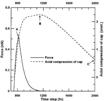
FIG. 2. Variation in repulsive force and axial compression of cap over duration of simulation for a共4,4兲 capped carbon nanotube.
pression, and tip withdrawal from the surface. These snap-shots are indicated in the figures by the labels 共a兲, 共b兲, and 共c兲, respectively. Meanwhile, these points are indicated in Figs. 2, 3, and 4 by the labels A, B, and C, respectively.
Figure 2 demonstrates that the repulsive force is approxi-mately proportional to the magnitude of the axial
compres-sion until the point at which the critical force is attained. Within this region of proportionality, the cap behavior re-sembles that of a spring with a constant of 1.4 nN/Å共i.e., the ratio of the critical force to the corresponding axial compres-sion magnitude兲. Beyond the point of critical force, the re-pulsive force decreases rapidly, while the magnitude of the axial compression continues to rise. Clearly, this behavior does not obey Hooke’s law for a spring. Rather, this phenom-enon can be attributed to the radial compression of the cap, during which the bond orientations and lengths change in order to relieve the force acting upon them. Figure 5共b兲 shows the morphology associated with the maximum axial compression within the共4,4兲 carbon nanotube. From a com-parison with Fig. 5共a兲, it is clear that the sp2 bond orienta-tions which originally existed between the carbon atoms of the cap at the point of critical force have changed such that they lie in one flat plane. From Fig. 2, it can be seen that after the point of maximum axial compression, the magni-tudes of the force and the axial compression decrease. As shown in Fig. 5共c兲, when the tip is withdrawn from the graphite surface, the force approaches a value of zero when the distance between the cap and the surface exceeds the cutoff distance. Under these conditions, the carbon atoms recover their initial arrangement.
Figures 3 and 4 show the variations of the repulsive force and the axial compression of the 共7,7兲 and 共11,11兲 capped carbon nanotubes over the course of the simulation.
FIG. 3. Variation in repulsive force and axial compression of cap over duration of simulation for a共7,7兲 capped carbon nanotube.
FIG. 4. Variation in repulsive force and axial compression of cap over duration of simulation for a共11,11兲 capped carbon nanotube.
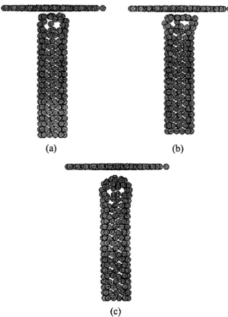
FIG. 5. Characteristic morphologies of共4,4兲 capped carbon nanotube: 共a兲 at point of critical force;共b兲 at point of maximum axial compression in cap; and共c兲 following withdrawal of cap from graphite surface.
It is immediately obvious that the characteristics of the re-pulsive force in both cases strongly resemble the trend dis-cussed above for the 共4,4兲 capped carbon nanotube. As be-fore, the deformation of the cap conforms to Hooke’s law until the point at which the repulsive force causes radial de-formation. Thereafter, the force is relieved, and the axial compression increases accordingly. This process is illustrated more clearly by the morphologies presented in Figs. 6共a兲 and 6共b兲 for the 共7,7兲 carbon nanotube, and in Figs. 7共a兲 and 7共b兲 for the 共11,11兲 nanotube. In both sets of figures, the bond orientations and lengths are seen to change over the time interval between the point of critical force and the point of maximum axial compression. Finally, as shown in Figs. 6共c兲 and 7共c兲, the atomic arrangements of both carbon nanotubes return to their original configurations as the tip moves away from the surface causing the force to fall toward zero. A careful comparison of Figs. 2, 3, and 4 reveals that the prin-cipal influence of the nanotube radius is to determine the magnitude of the axial compression of the cap once it is withdrawn from the graphite surface. For a cap of smaller diameter, such as that of the共4,4兲 nanotube, the cap rapidly recovers its original structure once it exits the surface. This point is represented by label C in Fig. 2, in which it can be seen that both the repulsive force and the axial compression fall to a value of zero at an elapsed simulation time of ap-proximately 1200 fs. However, for the larger radii共7,7兲 and 共11,11兲 carbon nanotubes, the simulation results indicate that the cap remains in a compressed state shortly after it has been withdrawn from the surface at approximately 1100 fs. Even after an elapsed time of 2000 fs, Figs. 3 and 4 show that the axial compression has still not reduced to a value of zero, thus indicating the presence of a residual compressive stress within the nanotube. This result is to be expected since there are a greater number of bond orientations and lengths to be changed in a cap of larger diameter, and hence more
time is required for the atomic arrangement to return to its original configuration. Although the axial compressions of the 共7,7兲 and 共11,11兲 carbon nanotube caps are not zero at 2000 fs, plastic deformation does not occur because the co-valent bonds of the carbon atoms of the cap are not broken, even at the axial compression associated with the maximum repulsive force 关as shown in Figs. 6共a兲 and 7共a兲兴. Since no carbon atoms change their covalence bonding with neighbor-ing carbon atoms as its original bondneighbor-ing, the capped carbon nanotubes recover their original shapes after 2000 fs. This is because the original structure with its original bond lengths and orientations represents the most stable structure.
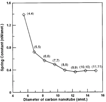
Figure 8 shows the relationship between the spring con-stant and the carbon nanotube diameter for eight nanotubes in the range of共4,4兲 to 共11,11兲. In general, it is noted that the spring constant initially decreases as the radius of the nano-tube increases, but then assumes a stable value as the radius continues to increase. The 共4,4兲 nanotube has the highest spring constant value of approximately 1.4 nN/Å, while the radius of the 共8,8兲 armchair carbon nanotube represents the radius at which the spring constant attains a stable value of approximately 0.4 nN/Å. The smaller the spring constant value, the softer the end of the cap will be. This result can be attributed to the different strain energies of the carbon atoms in carbon nanotubes of different diameters. This strain
en-FIG. 6. Characteristic morphologies of共7,7兲 capped carbon nanotube: 共a兲 at point of critical force;共b兲 at point of maximum axial compression in cap; and共c兲 following withdrawal of cap from graphite surface.
FIG. 7. Characteristic morphologies of共11,11兲 capped carbon nanotube: 共a兲 at point of critical force;共b兲 at point of maximum axial compression in cap; and共c兲 following withdrawal of cap from graphite surface.
ergy represents the energy required to remove the carbon atom from the carbon nanotube.15Previous tight-binding mo-lecular dynamics simulation reveals that the strain energy decreases significantly as the diameter changes from that of a 共4,4兲 carbon nanotube to that of a 共8,8兲 carbon nanotube, but exhibits little further change as the diameter continues to increase.15 Therefore, carbon nanotubes with smaller radii will be stiffer than those with larger radii. Furthermore, the strain energies of the 共4,4兲 and 共8,8兲 carbon nanotubes are approximately 0.32 and 0.09 eV/atom,15 respectively, which corresponds to a ratio of approximately 3.5. The results of the present study yield spring constants for the 共4,4兲 and 共8,8兲 nanotubes of 1.4 and 0.4 nN/Å, respectively, which also corresponds to a ratio of 3.5. The fact that these two ratios have a common value confirms that the strength or stiffness of a carbon nanotube depends on its diameter. Consequently, the results of Fig. 8 demonstrate that the caps of carbon nanotubes with radii larger than that of the 共8,8兲 armchair carbon nanotube are more flexible, and will therefore provide better shock absorption properties. As a result, these particu-lar nanotubes are more suitable for the probing of soft sur-faces since they are less likely to cause surface damage.
In the Yao and Lordi study,9 the spring constant of the 共10,10兲 carbon nanotube was found to be 9.35 nN/Å, which is approximately 20 times greater than the value obtained in the current study. This discrepancy can be attributed to the limitation of the UFF potential model. The UFF potential model employs the harmonic form of the bond stretching energy. This model is only reasonable when the variation of the specific bond length from the reference bond length is small since the parabolic curve of the relationship between the bonding energy and the bond length is only accurate when this condition is satisfied.24If the specific bond length is much larger or smaller than the reference bond length, the modeled variation of the bonding energy with the bond length is much sharper than the actual variation of the
bond-ing energy. This implies that the repulsive or attractive force obtained from the harmonic form is much larger than the actual value when the specific bond length is much larger or smaller than the reference bond length. In the current study, the bond lengths of the carbon atoms in the cap are changed from their reference bond lengths as the cap interacts with the graphite surface. With the same compression magnitude, the repulsive force calculated by the UFF potential model is larger than that predicted by the tight-binding scheme. Con-sequently, a larger spring constant is obtained if the UFF potential model is employed.
IV. CONCLUSIONS
This article has presented a tight-binding molecular dy-namics simulation investigation into the complex deforma-tion mechanisms of capped carbon nanotubes during the in-dentation of a graphite surface. The results have shown that the cap initially behaves like a spring in that it obeys Hooke’s law until a certain critical repulsive force causes radial deformation of the cap. This deformation occurs as the bond orientations and lengths of the atoms within the cap are rearranged in order to relieve forces in the cap. It has been shown that following deformation, the cap behavior no longer conforms to Hooke’s law, and that the reduction in repulsive force is accompanied by an increase in the magni-tude of the axial compression. The axial compression in-creases to a maximum value and then reduces toward a value of zero. The simulation results have also shown that since more covalent bonds participate in relieving the force ex-erted on the cap of a nanotube of larger diameter, more time is required for the atomic arrangement to return to its origi-nal configuration. Fiorigi-nally, this study has explored the rela-tionship between the spring constant and the carbon nano-tube radius. It has been shown that the共4,4兲 carbon nanotube has the highest spring constant 共approximately 1.4 nN/Å兲, and that the spring constant assumes a stable value of ap-proximately 0.4 nN/Å when the radius of the nanotube ex-ceeds that of the 共8,8兲 carbon nanotube.
Since an increasing number of applications are being proposed for capped carbon nanotubes, there is an urgent requirement to determine the material properties of nano-tubes of different radii. It is the current authors’ belief that the present molecular dynamics simulation results provide a valuable insight into the deformation mechanisms, which oc-cur at the atomistic scale in the tip of a capped carbon nano-tube when used in the tapping mode measurement process.
ACKNOWLEDGMENTS
The authors gratefully acknowledge the support pro-vided to this research by the National Science Council of the Republic of China under Grant No. NSC 92-2212-E-110-030.
1H. Dai, J. H. Hafner, A. G. Rinzler, D. T. Colbert, and R. E. Smalley,
Nature共London兲 384, 147 共1996兲.
2
Y. Nakayama, H. Nishijima, and S. Akita, J. Vac. Sci. Technol. B 18, 661
共2000兲.
3S. Akita, H. Nishijima, and Y. Nakayama, J. Phys. D 33, 2673共2000兲.
FIG. 8. Variation in cap spring constant value with carbon nanotube diam-eter.
4E. S. Snow, P. M. Campbell, and J. P. Novak, Appl. Phys. Lett. 80, 2002
共2002兲.
5Y. Nakayama, Ultramicroscopy 91, 49共2002兲.
6J. A. Harrison, S. J. Stuart, D. H. Robertson, and C. T. White, J. Phys.
Chem. B 101, 9682共1997兲.
7
A. Garg, J. Han, and S. B. Sinnott, Phys. Rev. Lett. 81, 2260共1998兲.
8
A. Garg, and S. B. Sinnott, Phys. Rev. B 60, 13 786共1999兲.
9N. Yao, and V. Lordi, Phys. Rev. B 58, 12 649共1998兲. 10A. K. Rappe´ et al., J. Am. Chem. Soc. 114, 10 024共1992兲.
11C. S. Casewit, K. S. Colwell, and A. K. Rappe´, J. Am. Chem. Soc. 114,
10 035共1992兲.
12A. K. Rappe´, K. S. Colwell, and C. J. Casewit, Inorg. Chem. 32, 3438
共1993兲.
13C. H. Xu, C. Z. Wang, C. T. Chan, and K. M. Ho, J. Phys. A 4, 6047
共1992兲.
14L. Colombo, Comput. Mater. Sci. 12, 278共1998兲. 15
D. H. Oh and Y. H. Lee, Phys. Rev. B 58, 7407共1998兲.
16T. Ozaki, Y. Iwasa, and T. Mitani, Phys. Rev. Lett. 84, 1712共2000兲. 17G. Dereli and C. Ozdogan, Phys. Rev. B 67, 035 416共2003兲.
18R. Che, L. M. Peng, S. Zhang, and Z. Sun, Chem. Phys. Lett. 368, 20
共2003兲.
19
C. Z. Wang, B. L. Zhang, and K. M. Ho, in Computational Studies of New Materials, edited by D. A. Jelski and T. F. George共World Scientific, Sin-gapore, 1999兲, pp. 74–111.
20C. Z. Wang, K. M. Ho, and C. T. Chan, Phys. Rev. B 47, 14 835共1993兲. 21
V. Rosato, M. Celino, and L. Colombo, Chem. Phys. Lett. 10, 67共1998兲.
22J. C. Slater and G. F. Koster, Phys. Rev. 94, 1498共1954兲.
23J. M. Haile: Molecular Dynamic Simulation共Wiley, New York, 1992兲. 24A. R. Leach, Molecular Modelling, Principle and Applications,