An Optimal Pixel-level Self-repairing Authentication Method for Grayscale Images under a Minimax
Criterion of Distortion Reduction*
Che-Wei Lee1and Wen-Hsiang Tsai1,2,
1Department of Computer Science and Information Engineering
National Chiao Tung University, Hsinchu, Taiwan 30010
2Department of Information Communication
Asia University, Taichung, Taiwan 41354 Tel: +886-3-5728368 Fax: +886-3-5734935
E-mails: [email protected] & [email protected]
* This work is supported financially by the National Science Council, Taiwan, ROC under Project No.
99-2631-H-009-001.
Abstract
A new blind pixel-level self-repairing grayscale image authentication method, which is optimal under a minimax criterion of image distortion reduction, is proposed. By dividing the grayscale range into bins, a 3-bit bin code which provides the double functions of tampering localization and data repairing is generated as the authentication signal for each pixel in the cover image. The optimality in choosing three bits of a pixel as the authentication signal under a minimax criterion of minimizing the total maximum distortion resulting from authentication signal embedding and tampered pixel repairing is proved. Experimental results show the effectiveness of the proposed method.
Key words: fragile watermarking, grayscale image authentication, image tampering, tampering localization, tampered data repairing.
1. Introduction
With the era of cloud computing coming, data stored originally in personal computers mostly will eventually be moved to and processed in powerful servers at far ends. However, how can one be sure that personal data accessed from cloud servers are intact? Undoubtedly, this problem of data security has become a significant issue in the age of cloud computing.
This study explores the security issue of keeping digital image data. The use of an image authentication technique provides a solution to this issue. A new grayscale image
authentication method is proposed in this paper. By embedding fragile authentication signals into a cover image to be protected to create a stego-image, illicit modifications made to the stego-image may be localized to the pixel-level precision by the proposed method such that the integrity and fidelity of the original image content can be checked.
An example of scenarios of applying the method goes like this. A lawyer, say Bob, always saves the critical grayscale document images of one of his clients, say Alice, into a cloud server through the Internet. Each of such images is a stego-image yielded by the proposed method with almost no difference in appearance from the original cover image.
One day, Bob retrieves from the far-end server the stego-image of a document required for a court session scheduled for Alice in the next day. For the purpose of checking the authenticity of the stego-image, Bob fetches a private key he keeps personally and authenticates the image by the proposed method with the key as an input. Unfortunately, a portion of the
stego-image is found non-identical to its original content and marked out by the method as an alert to Bob, indicating that the image has been tampered illegally at the server site. Instead of abandoning the attacked stego-image, Bob may try to repair the tampered image portion by using the proposed method and keeps the resulting image for further uses in the court or in other later activities.
Several fragile watermarking techniques for image authentication have been proposed in the past and they may be categorized into two approaches: block-wise [1-7] and pixel-wise [8-11]. Methods of the former approach embed fragile watermarks as authentication signals into non-overlapping blocks of the cover image and identify possible tampered image parts in the unit of block. One weakness of such block-level authentication methods is that the detail of the tampered image part cannot be located precisely [9]. On the other hand, methods of the second approach [8-11] authenticate images at the pixel level such that tampered image parts can be identified pixel by pixel, yielding a detailed tampering localization result. Liu et al. [8]
generated a binary image that is mapped from the difference image computed from the cover image and its so-called chaotic pattern. And the least-significant-bit (LSB) plane was used to accommodate the binary image as the fragile watermark for the use in later image authentication. Because of the binary nature of the embedded fragile watermark, the LSB of a tampered pixel value may coincide with the watermark bit, yielding a high erroneous pixel authentication rate up to 50%. To deal with this phenomenon, a statistical fragile watermarking method which utilizes probability distributions computed from the original
pixels and the tampered ones to locate the tampered pixels was proposed in Zhang and Wang [9]. However, the method only works in the case that the tampering ratio is smaller than 1.1%
[10]. As an improvement, Zhang and Wang [10] proposed later a fragile watermarking method for authenticating grayscale images using a hierarchical mechanism, which embeds watermark data derived from the pixels and blocks of the cover image into the LSBs of all the pixels. In the authentication process, tampered blocks are identified first, and tampered pixels within the identified blocks are located subsequently.
In this study, a method for pixel-level grayscale image authentication using fragile authentication signals with an additional capability for repairing attacked image parts automatically is proposed. The method is based on the concept of compressing a number of the most significant bits (MSBs) of a pixel’s gray value into a shorter “bin code” for use both as an authentication signal for the pixel and as an index for generating the data for repairing the pixel when it is authenticated to have been tampered with. The bin code is generated from a bin-mapping scheme which transforms each pixel’s gray value into one of eight “bins,”
coded by three bits. It is proved that the choice of using three bits out of eight ones in a pixel as the bin code is optimal under a minimax criterion of reducing the total maximum pixel-level gray-value distortion resulting both from authentication signal embedding and from tampered pixel repairing.
The proposed method has at least four merits. (1) First, different from other methods
the proposed method uses the above-mentioned single bin code to function as the two items simultaneously, leading to use of less storage for embedding these data in the image. (2) The
use of less storage leads further to the possibility of conducting more precise pixel-level authentication because it becomes now possible to allow every pixel to include the pixel authentication signal (saved as the three LSBs) in addition to the original pixel content (kept in the five MSBs). Note that most related methods with data repairing capabilities authenticate images at the block level [14-16], yielding coarser tampering localization and data repairing results. (3) Furthermore, a secret key is used in the proposed method for randomly choosing pixels for embedding the generated authentication signals, thus increasing the security of the stego-image yielded by the proposed method. (4) Finally, because of the first merit of using less storage for authentication and repairing data mentioned previously, the proposed method is blind [17] in nature no information other than the image itself is needed for conducting the data repairing process. Note that the methods of [2, 3, 6, 8, 12] need to know the prior information of the hidden digital signatures or watermarks [17] used in the authentication process. Besides, extra information like codebooks or other overhead data is required in some existing methods with data repairing capabilities [6, 12, 16].
The remainder of this paper is organized as follows. In Section II, the details of the proposed method are described. In Section III, the previously-mentioned optimality of the choice of three bits as the bin code for use as the authentication signal is proved. Some
experimental results showing the feasibility of the proposed method are presented in Section IV. And finally conclusions are made in Section V.
2. Proposed Method for Pixel-level Grayscale Image Authentication and Self-repairing
A. Authentication Signal Generation and Embedding
In the proposed method for grayscale image authentication and self-repairing, the 8-bit gray value g of each pixel in an input image is divided into two parts the five MSBs of g and the remaining three LSBs. The former is used to generate an authentication signal for the pixel itself, with the signal also working as an index for generating the data for repairing the pixel’s gray value when the pixel is authenticated to have been tampered with. The five MSBs ideally are expected to be embedded directly in a randomly-selected pixel elsewhere and can be retrieved later for use in the two previously-mentioned purposes of authentication signal and repairing data generations. However, due to the limited data hiding capacity in the image, it is difficult to embed the large-volume data consisting of such MSBs of all the pixels into the input image; and even if they could be embedded, noticeable distortion would be created. Consequently, we propose in this study to use a bin-mapping scheme for the purpose of compressing these MSB data before embedding them. Specifically, we map the gray-value range specified by the five MSBs into eight equal-length intervals called bins, with each bin being indexed by an integer called a bin number, or equivalently, by a 3-bit binary number,
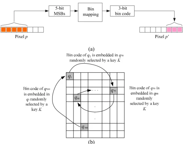
called a bin code. The eight bins and their corresponding bin numbers and bin codes are shown in Table I. The bin code of each pixel is then taken as the authentication signal of the pixel and embedded into the three remaining LSBs (the previously-mentioned second part) of another pixel randomly chosen by a pre-selected secret key. An illustration of these ideas of
authentication signal (bin code) generation and embedding is given in Fig. 1, and the detail is described as an algorithm in the following.
5-bit MSBs
Bin mapping
3-bit bin code
Pixel p Pixel p'
(a)
(b)
Fig. 1. Illustration of bin code (authentication signal) generation and embedding. (a) Mapping 5-bit MSBs to a 3-bit bin code. (b) Bin codes embedded into pixels randomly selected by a secret key K.
Algorithm 1: authentication signal generation and embedding.
Input: a grayscale cover image I, a random number generator f, and a secret key K.
Output: a stego-image Is with authentication signals embedded.
Steps.
Step 1. (Beginning of looping) In a raster-scan order, select a pixel p from the image I.
Step 2. (Authentication signal generation and embedding) Perform the following steps to generate an authentication signal for p and embed it into another randomly-selected pixel.
2.1 Transform the gray value of p into eight bits, b7, b6, …, b0. 2.2 Transform the five MSBs, b7, b6, …, b3, of p into an integer d.
2.3 Map the integer d into a bin indexed by a bin number B computed by the function B = d/4 where specifies the integer floor function.
2.4 Transform B into a 3-bit bin code s = c2c1c0 for use as the authentication signal for p.
2.5 Select randomly a pixel p′ in I other than p using the input random number generator f with the input key K as the seed, and regard pixel p′ as corresponding to p.
2.6 Embed the 3-bit authentication signal s = c2c1c0 of p into p by replacing the three LSBs of p with s.
Step 3. (End of looping) If there remain unprocessed pixels in I, then go to Step 1;
otherwise, take the final I as the desired stego-image Is.
In the above algorithm, Steps 2.2 through 2.4 are used to show how the concept of bin mapping of our method is applied. In practice, these steps may be reduced to be simply as follows for use in real applications.
2.2 Take the 3 MSBs b7b6b5 of p to yield a bin code denoted as s = c2c1c0. B. Image Authentication, Tampering Detection, and Data Repairing
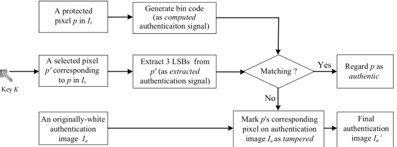
During the image authentication process, an authentication signal is computed from the five MSBs of every pixel p. Also, the authentication signal embedded in the three LSBs of the pixel p corresponding to p, which was randomly selected previously in Algorithm 1, is retrieved. The two authentication signals then are compared with each other. If mismatching occurs, pixel p is regarded as having been tampered with. In this case, we use again the three LSBs of pixel p, which is also the bin code of p, as an index to generate a data item for use in repairing the tampered gray values of p. The generated data item is taken to be the middle value of the bin indexed by the bin code, which is called the representative value of the bin and denoted by M. Specifically, M is computed as M = (a + b)/2 for a bin with range [a, b]
where specifies the integer ceiling operation. The representative value M for each bin used in this study is shown in the rightmost column of Table I, though it may be computed analytically directly (for the detail, see Section III later). Finally, after padding three trailing 0’s to M, the result is used to repair the tampered pixel. A diagram illustrating the above idea of authentication signal matching and tampered pixel detection is shown in Fig. 2. And another diagram illustrating the idea of tampered pixel repairing is shown in Fig. 3. Detailed
algorithms implementing these ideas are described subsequently.
A protected pixel p in Is
Generate bin code (as computed authenticaiton signal)
Extract 3 LSBs from p' (as extracted authentication signal) A selected pixel
p' corresponding to p in Is Key K
Matching ? Yes
No
Regard p as authentic
Mark p's corresponding pixel on authentication
image Ia as tampered An originally-white
authentication image Ia
Final authentication
image Ia
Fig. 2. Diagram of authentication signal matching and tampered pixel marking (detail to be described in Algorithm 2).
Fig. 3. Diagram of tampered pixel repairing (detail to be described in Algorithm 2).
Algorithm 2: image authentication, tampering detection, and data repairing.
Input: a stego-image Is generated by Algorithm 1 presumably, an originally-white authentication image Ia, and the random number generator f and the secret key K used in Algorithm 1.
Output: an image Ir with tampered pixels, if any, being repaired.
Step 1. (Beginning of looping for pixel authentication) Take in a raster-scan order a pixel p from Is, and perform the following steps.
Stage 1 --- computation of authentication signals.
1.1 Transform the gray value of p into eight bits b7, b6, …, b0. 1.2 Transform the five MSBs b7, b6, …, b3 of p into an integer d.
1.3 Map the integer d into a bin indexed by a bin number B computed by B = d/4.
1.4 Transform B into a 3-bit bin code s = c2c1c0 which is also regarded as an authentication signal, called the computed authentication signal.
Stage 2 --- extraction of the hidden authentication signal.
1.5 Use the random number generator f and the input key K as the seed to select from Is randomly a pixel p corresponding to p, where a previously-embedded authentication signal for p is located presumably.
1.6 Transform the gray value of p into eight bits b7′, b6′, …, b0′, extract the three LSBs to form a string s′ = b2′b1′b0′, called the extracted authentication signal.
Stage 3 --- authentication signal matching and tampered pixel marking.
1.7 Match the computed authentication signal s = c2c1c0 and the extracted one s′ = b2b1b0 bit by bit; and if mismatching occurs, regard p as having been tampered with and mark its corresponding pixel on the authentication image Ia as a black point.
1.8 (End of looping) If there remain unprocessed pixels in Is, then go to Step 1;
otherwise, take the final Ia as a new authentication image Ia for use in the next stage of the algorithm for image repairing.
Stage 4 --- tampered pixel repairing.
Step 2. (Beginning of looping for tampered pixel repairing) For each black point pa in Ia selected in the raster-scan order, perform the following steps.
2.1 For the pixel p in Is corresponding to pa, use the input random number generator f with the input key K as the seed to select randomly a pixel p where a previously-embedded authentication signal for p is located presumably.
2.2 Transform the gray value of p into eight bits b7′′, b6′′, …, b0′′, extract the three LSBs b2b1b0, and transform b2b1b0 into an integer B which specifies the index of the bin into which the gray value of p falls.
2.3 Repair the tampered pixel p by the following steps.
2.3.1 Derive the representative value M of the bin indexed by B.
2.3.2 Transform M into a 5-bit binary string r7r6r5r4r3.
2.3.3 Pad three trailing 0’s to r7r6r5r4r3 to get an 8-bit string T = r7r6r5r4r3000.
2.3.4 Transform T into an integer d and replace the gray value of p with d as the repairing result.
Step 3. (End of looping) If there remain unprocessed black pixels in Ia, then go to Step 2;
otherwise, take the final Is as the desired output image Ir.
C. An Illustrative Example
An example is given here to illustrate the above algorithms. Given a pixel p in the input
image with gray value 133, or equivalently, with gray value 10000101 in binary, the five MSBs and the three LSBs of p are m = 10000 and l = 101, respectively. The integer value of m is 16 and the bin mapping of it results in the bin number 16/4 = 4, so we get to know that
the bin into which m falls is indexed by 4. The binary form 100 of this bin number 4, i.e., the bin code is 100, which is then taken as the authentication signal s for p. Also, assume that another pixel p, say, of gray value 231 is selected randomly to be corresponding to p using a certain random number generator f with a pre-selected secret key K as the seed. The binary form of 231 is 11100111. So, the three LSBs of this binary number are replaced by the authentication signal s = 100 of p, resulting in a binary value of 11100100, or an integer of 228, which is then taken to be the new gray value of pixel p as the authentication signal generation and embedding result conducted by Algorithm 1.
Now, suppose that the original gray value 133 of pixel p becomes 99, or 01100011 in binary, due to illicit tampering. Then, in the authentication process conducted by Algorithm 2, the five MSBs of this tampered binary gray value, namely, 01100, or 12 in decimal, is used to obtain the computed authentication signal s = 011 by the bin mapping 12/4 = 310 = 0112. On the other hand, applying the random number generator f with the secret key K used before as the seed, we select again the pixel p corresponding to p with gray value 228 as mentioned previously. The authentication signal for pixel p presumably is embedded at p′. To extract it, we transform again the gray value 288 of p′ into the binary form 11100100. We then take the three LSBs s′ = 100 as the extracted authentication signal. Comparing this signal s′ = 100
with the computed authentication signal s = 011 bit by bit, we decide that the pixel p has been tampered with because the bits in each of three corresponding bit pairs are different.
We now have to repair p using the information of the extracted authentication signal s′ = 1002. Since 1002 = 410, s′ specifies a bin indexed by 4. Because the interval of bin 4 is [16, 19], we get the representative value M of this bin to be M = 1710 = 100012 according to Table I. After padding three trailing zeros M in the binary form, we get a gray value of 100010002 = 13610, which is finally taken to be the new gray value of p as the tampering repairing result.
As a comparison, note that p originally has the gray value of 13310, which shows that the repairing result is close to the original value.
3. Proof of Optimality of Proposed Method for Image Distortion Reduction
In the proposed method presented above, the eight bits of each pixel’s gray value is separated into two parts, five MSBs and three LSBs, with the former used for keeping the pixel content and the latter used for embedding the authentication signal. It seems that we may generalize this specific choice of pixel-bit division, (m, l) = (5, 3), where m denotes the number of MSBs and l the number of LSBs with m + l = 8. For example, we may choose alternatively to use two LSBs in a pixel for embedding the authentication signal and the remaining six bits for keeping the pixel content, so that (m, l) = (6, 2). Or, by a reverse consideration, we may choose to adopt (m, l) = (4, 4) as well. Is there a criterion to decide
which choice is better? The answer proposed in this study is to consider the resulting image distortion.
It will be proved in this section that the choice of m = 5 and l = 3 as done in this study is optimal in the sense of minimizing the resulting total image distortion incurred both by
authentication signal embedding and by tampered pixel repairing. The proof is conducted in a step-by-step reasoning manner as described in the following.
Proof of the optimal choice of the number of bits for use as the authentication signal.
Stage 1 optimization criterion consideration in terms of resulting image distortion.
(1) First, we consider simultaneously at the pixel-level the maximum distortion D1 resulting from the process of embedding authentication signals as well as the maximum distortion D2 resulting from the process of repairing tampered pixels, and take their sum D = D1 + D2 as the criterion function for optimization in choosing the values of (m, l), i.e., for dividing the eight bits of a pixel’s gray value into two parts for the purposes described previously. The goal is to obtain a choice of (m, l) which minimizes the value of D, or equivalently, the maximum distortion coming from authentication signal embedding and tampered pixel repairing for each pixel.
(2) Since m + l = 8, we just have to choose an optimal value for l under the above-mentioned minimax criterion, and take the value of m to be m = 8 l.
Stage 2 derivation of distortion incurred by authentication signal embedding.
(3) As mentioned, l LSBs of a pixel p are used to compose a bin code which is then taken to be the authentication signal s of p and embedded in another pixel p′ (see Step 2 of Algorithm 1). And this will incur a maximum gray-value changes of 2l 1 coming from either of the two cases of bit changes from l 0’s to l 1’s and from l 1’s to l 0’s.
(4) Therefore, the maximum gray-value distortion occurring at each pixel resulting from authentication signal embedding is D1 = 2l 1.
Stage 3 derivation of distortion resulting from tampered pixel repairing.
(5) The width of the total range of gray values specified by the m MSBs of a pixel is 2m which is divided into 2l bins (see Step 2 of Algorithm 1), so the width Wbin of each bin is
Wbin = 2m/2l = (28l)/2l = 282l
because m + l = 8 as explained before.
(6) Accordingly, if the range of the xth bin Bx is denoted by [L, R], then it is easy to figure out that L = (x 1)×28land R = x×28l 1 and, where x = 1, 2, …, 2l (see Table I for numerical examples of [L, R]).
(7) Then, the representative value M of Bx (computed in Step 2 of Algorithm 2), which is the middle value between L and R, is just
M = (L + R)/2 = [((x 1)×28l)+ (x×28l 1)]/2
= x×28l 27l 21.
(8) With M as the representative value for all the gray values in bin Bx used in repairing a
tampered pixel p, the maximum gray-value difference D′ between the repaired m MSBs of pixel p and the original m ones is M L (or R M) which may be computed to be
D′ = M L = (x×28l 27l 21) (x 1)×28l
= 272l 21.
(9) Since we pad l trailing zeros to the m MSBs of the representative value M (see Step 2 in Algorithm 2) to compose an 8-bit number to repair the tampered pixel p, the maximum gray-value distortion after repairing p is
D2 = D′×2l + (2l 1)
where the term 2l 1 specifies the partial distortion coming from the extreme case that the original last l bits of p are all 1s.
(10) By using the result of D′ derived previously in (8), D2 may be derived in more detail to be
D2 = (272l 21)×2l + (2l 1).
= 27l + 2l1 1.
Stage 4 minimization of the overall distortion.
(11) The maximum gray-value distortion D considered for a pixel as mentioned previously in (1) now can be computed from the results of (4) and (10) above to be
D = D1 + D2 = (2l 1) + (27l + 2l1 1)
= 27l + 3×2l 2.
(12) Taking the derivative of D with respect to l, we get
dD/dl = 27l×ln2×[d(7l)/dl] + 3×2l×ln2×[d(l1)/dl]
= 27l×ln2×(1) + 3×2l×ln2×(+1)
= ln2×(3×2l 27l)
where ln2 is the natural logarithm value of 2.
(13) Setting dD/dl = 0, we can get the following equation
ln2×(3×2l 27l) = 0
which may be solved to get
27l = 3×2l,
or equivalently,
(27l)/(2l1) = 282l = 3.
(14) Taking the base-2 logarithm values of the two sides of the above equality and simplifying the result, we get finally the solution of l as:
l = 4 log2 3]/2
which may be evaluated explicitly to be approximatelyequal to 3.2075.
(15) Accordingly, since l is the number of LSBs which should be an integer, it is taken to be the integers 3 and 4 for which the corresponding values of the gray-value distortion D
73 3l 74 4l
Therefore, the optimal l is finally decided to be 3 which is exactly the number of bits we use to compose an authentication signal as described previously. This completes the proof.
4. Experimental Results
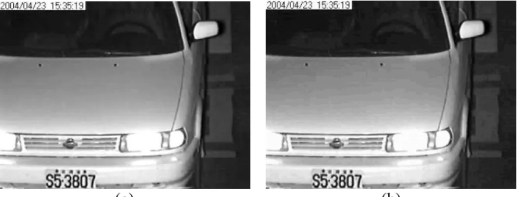
Many experiments have been conducted to test the proposed method and one result is shown in Fig. 4, where Fig. 4(a) is an input surveillance image with the size of 480×360. The result of applying Algorithm 1 to generate and embed authentication signals into Fig. 4(a) is shown in Fig. 4(b) with a PSNR value of 37.51. Actually, a general lower bound may be computed for this PSNR value, as done by the following reasoning.
(1) With l being the number of bits in a pixel used for embedding the authentication signal, the largest mean square error value MSE of a stego-image with respect to the cover image is (2l 1)2 because at each pixel, the largest gray-value difference is 2l 1 after an l-bit authentication signal is embedded there, as described previously.
(2) Accordingly, the peak-signal-to-noise-ratio value PSNR by definition is just
PSNR = 10log10(2552/MSE)
= 10log10[2552/(2l 1)2]
= 20log10[255/(2l 1)]
= 20log10(255/7)
31.23
where 255 is the maximum gray value of an 8-bit pixel and l is 3 for our case here.
(3) That is, the lowest bound for the PSNR value is approximately 31.23, which means that the quality of the stego-image is good enough for general applications.
(a) (b)
Fig. 4. Generation of stego-image from an input surveillance image. (a) Input image taken by a monitor. (b) Stego-image with PSNR value 37.51.
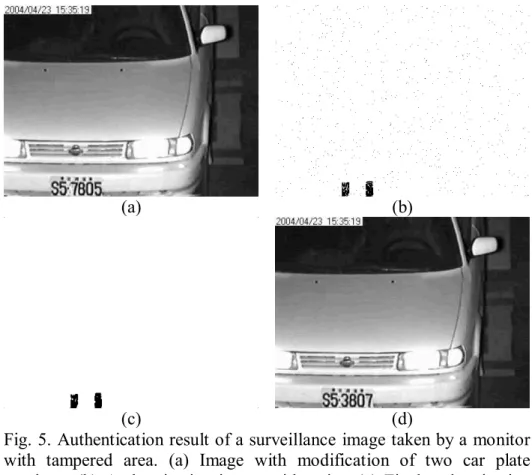
Back to the presentation of the first case in our experimental results, Fig. 5(a) shows a tampering result with a tampering ratio of 0.74% in which two numbers “3” and “7” on the car plate shown in Fig. 4(b) were replaced with fake numbers “7” and “5”, respectively. Fig.
5(b) shows the obtained authentication image after applying Stages 1 through 3 of Algorithm 2 to Fig. 5(a). As can be seen, the tampered pixels covered by the fake numbers have been detected correctly. However, some noise points can be seen to appear in Fig. 5(b). These noise points indicate that the pixels in the original image corresponding to these noise points are also erroneously authenticated as having been tampered with. The reason for this noise phenomenon is explained in the following.
(a) (b)
(c) (d)
Fig. 5. Authentication result of a surveillance image taken by a monitor with tampered area. (a) Image with modification of two car plate numbers. (b) Authentication image with noise. (c) Final authentication image. (d) Final repairing result with PSNR 45.60 with respect to stego-image.
If a pixel A is authenticated as having been tampered with, it means that the authentication signal of a pixel B, which is embedded at pixel A, is also damaged. This in turn means that B will also be authenticated as having been tampered with, even when B is in fact not so. This effect of mutual affection leads to erroneous marking of single points in the authentication image as tampered pixels, creating a pepper-and-salt noise phenomenon like that seen in Fig. 5(b). To remove this effect, we applied the median filtering operation to eliminate such noise points before performing the pixel repairing operations described in Stage 4 of Algorithm 2. The final authentication image resulting from doing so to Fig. 5(b) is shown in Fig. 5(c), in which, as can be seen, most pepper-and-salt points have been
eliminated, but 90 false acceptance pixels and 1 false rejection pixels are left. To deal further with this authentication image, image repairing was conducted and the result is shown in Fig.
5(d), in which we see that the original numbers “3” and “7” have been repaired successfully at their original positions. Also, with the tampered pixel repaired, the image has a PSNR value of 45.6 with respect to the stego-image shown in Fig. 4(b).
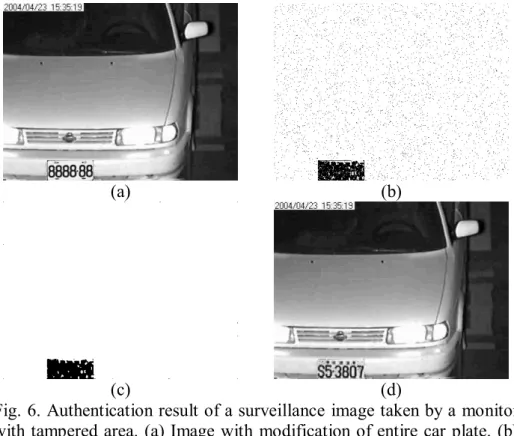
Another experimental result of replacing the entire car plate with a fake one is shown in Fig. 6. Compared with the previous experimental result with the tampering ratio being 0.74%, the tampering ratio in this case was raised to be 2.25%. It can be seen in Fig. 6(b) that the phenomenon of noise points caused by the effect of mutual affection becomes more conspicuous than that in the previous case because of the higher tampering ratio. After noise elimination was performed on Fig. 6(b), the final authentication image of Fig. 6(c) was obtained, which includes 551 false acceptance pixels (due to the reason that the five MSBs of each of them coincide with those of the original image) and 16 false rejection pixels (due to the reason that their authentication signals embedded in the tampered area were destroyed).
Finally, the repaired image in which the original car plate reappeared clearly with a PSNR value of 36.38 is shown in Fig. 6(d). Some relevant statistics of the two cases mentioned above are given in Table II.
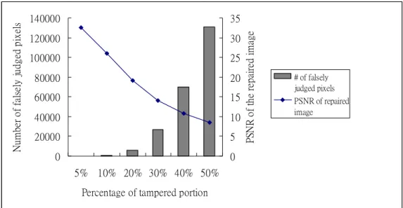
To show the relation of the performance of tampering localization and repairing to the degree of tampering as well as the use of median filtering, the statistics of the false judgments
of repaired images listed in the order of increasing tampering ratios are given in Table II. In addition, an illustration of the statistics is shown in Fig. 7. Note that the total numbers of false acceptance pixels plus false rejection pixels comprises the ordinate of the number of falsely judged pixels in Fig. 7.
(a) (b)
(c) (d)
Fig. 6. Authentication result of a surveillance image taken by a monitor with tampered area. (a) Image with modification of entire car plate. (b) Authentication image with noise. (c) Final authentication image. (d) Final repairing result with PSNR 36.38 with respect to stego-image.
0 10000 20000 30000 40000 50000 60000 70000 80000 90000 100000
5% 10% 20% 30% 40% 50%
tampering ratio
Number of falsely judged pixels
0 5 10 15 20 25 30 35
PSNR of the repaired image
# of falsely judged pixels PSNR of repaired image
Fig. 7. Relations of performances among tampering ratios, false tampering detection, and tampering repairing using surveillance image of Fig. 4(a).
In a subsequent experiment, we used another test image, Lena, of size 512×512 as shown in Fig. 8(a), and the stego-image yielded by the proposed method is shown in Fig. 8(b) whose PSNR value is 39.34.
(a) (b)
Fig. 8. Generation of stego-image from another image. (a) Input image Lena. (b) Stego-image with PSNR 39.34.
In this experiment, we selected the area of Lena’s hair and modified it by adding a rose flower shape of 2084 pixels on it. The modification result is shown in Fig. 9(a). Fig. 9(b) shows the authentication result without noise elimination, and the final authentication image is shown in Fig. 9(c) in which 2041 tampered pixels of the flower were detected and most isolated points were removed after median filtering. Finally, we repaired each of those detected pixels by referencing the bin code as the authentication signal embedded in a certain pixel whose position in Fig. 9(a) was located by a key. The repairing result in this case is shown in Fig. 9(d), and the PSNR value with respect to the stego-image is 47.00. Some other statistics about this case is given in Table III.
(a) (b)
(c) (d)
Fig. 9. Authentication result of a grayscale image with an added flower shape composed of 2084 pixels. (a) Image with modification of a hair portion. (b) Authentication image with noise. (c) Final authentication image. (d) Final repairing result with PSNR 47.00 with respect to stego-image of Fig. 9(b).
As done in the previous experiments using a surveillance image, we also gradually extended the tampered area in the Lena image to test the effectiveness of the proposed method. Table III lists the statistics of our experiments conducted in this way. Furthermore, an illustration corresponding to the statistics of Table III is shown in Fig. 10.
According to the results and statistics of all the conducted experiments, the proposed method is seen to be effective enough till the tampering ratio reaches about 10%. This overall result is better than that of the method described in [9] which works effectively when the tampering ratio is smaller than 1.1%.
0 20000 40000 60000 80000 100000 120000 140000
5% 10% 20% 30% 40% 50%
Percentage of tampered portion
Number of falsely judged pixels
0 5 10 15 20 25 30 35
PSNR of the repaired image
# of falsely judged pixels PSNR of repaired image
Fig. 10. Relations of performances among tampering ratios, tampering detection, and tampering repairing using image Lena of Fig. 8(a).
Table IV lists a comparison of the proposed method with other pixel-level image authentication methods [8-9] in terms of capabilities of self-recovery and tampered-pixel detection. We conducted an experiment that was also conducted in [9] with 2084 tampered pixels. The experimental result is exactly that of Fig. 9 given above. From Table IV, it can be seen that the proposed method provides better performance in the aspects of tampered pixels detection and tampering ratio limitation, and has the additional self-recovery capability. In addition, due to the characteristic of pixel-level authentication, we can recover the tampered area by the unit of pixel and so can recognize the detailed part existing in the original image after the recovery work.
To reveal further the characteristics of the proposed method, an image authentication method [12] based on the similar concept of using compressed codes was compared with. As can be observed in Table V, the proposed method can recover tampered areas at the pixel
auxiliary data item, a code book, is needed for image repairing. This leads to inconvenience and non-blindness in the image recovery process because extra storage space is required for the auxiliary data and the image repairing work cannot be done without referring to the auxiliary data. On the contrary, the proposed method is characterized as blindness.
Table V. Comparison of performance of proposed method with those of [12].
Authentication
methods Protected area Pixel level
Free from the need of auxiliary information
for recovery
Schemes used for image recovery Method of [12] Partial (region of
importance) No No Fractal code and
image painting Proposed
method Unrestricted Yes Yes Bin code
Some issues deserve further investigation in the future, for example, noise attacks.
Though this kind of attacks can be detected with the aid of human vision in the proposed method, a feasible criterion which can be used to distinguish noise points in the authentication image caused by mutual affection from those resulting from noise attack is desired.
5. Conclusions
A grayscale image authentication method with a capability of localizing tampered image regions and repairing them at the pixel level has been proposed. Based on a bin-mapping scheme of dividing the 5-bit grayscale into eight bins, a 3-bit bin code is generated for use as an authentication signal for each input image pixel. The authentication signals are embedded
into other pixels selected randomly by a secret key. The signals are utilized not only for detecting and localizing tampered pixels but also for generating representative values for repairing the tampered pixels. This double-function merit of the authentication signal leads to the possibility of pixel-level tampering detection and the blindness characteristic of the proposed method. Also shown is a proof of the optimality of the proposed method in choosing three bits out of the eight ones of a pixel as an authentication signal under a minimax criterion of minimizing the maximum total gray-value distortion incurred by authentication signal embedding and tampered pixel repairing. Experimental results have shown the effectiveness of the proposed method for authenticating and repairing tampered real images. Future works may be directed to extending the method to deal with color images.
References
[1] M. U. Celik, G. Sharma, E. Saber and A. M. Tekalp, “Hierarchical watermarking for secure image authentication with localization,” IEEE Trans. Image Process., vol. 11, no.
6, pp. 585-595, 2002.
[2] P. W. Wong and N. Memon, “Secret and public key image watermarking schemes for image authentication and ownership verification,” IEEE Trans. Image Process., vol. 10, no. 10, pp. 1593-1601, 2001.
[3] C. S. Lu and H. Y. M. Liao, “Structural digital signature for image authentication: an incidental distortion resistant scheme,” IEEE Trans. Image Process., vol. 5, no. 2, pp.
161-173, 2003.
[4] C. S. Lu and H. Y. M. Liao, “Multipurpose watermarking for image authentication and protection,” IEEE Trans. Image Process., vol. 10, no. 10, pp. 1579-1592, 2001.
[5] C. H. Tzeng and W. H. Tsai, "A new technique for authentication of image/video for
New Challenges, Ottawa, Ontario, Canada, pp. 23-26, 2001.
[6] C. W. Yang and J. J. Shen, “Recover the tampered image based on VQ indexing,” Signal Processing, vol. 90, no. 1, pp. 331-343, Jan. 2010.
[7] T. Y. Lee and S. D. Lin, “Dual watermark for image tamper detection and recovery,”
Patt. Recog., vol. 41, pp. 3497-3506, 2008.
[8] S. H. Liu, H. X. Yao, W. Gao, and Y. L. Liu, “An image fragile watermark scheme based on chaotic image pattern and pixel-pairs,” Appl. Math. Comput., vol. 185, no. 2, pp.
869-882, 2007.
[9] X. Zhang and S. Wang, “Statistical fragile watermarking capable of locating individual tampered pixels,” IEEE Signal Process. Letters, vol. 14, no. 10, pp. 727-730, Oct. 2007.
[10] X. Zhang and S. Wang, “Fragile watermarking scheme using a hierarchical mechanism,”
Signal Processing, vol. 89, no. 4, pp. 675-679, 2009.
[11] C. W. Lee and W. H. Tsai, “A grayscale image authentication method with a pixel-level self-recovering capability against image tampering,” Proc. 2011 IAPR Int’l Conf. on Machine Vision Applications, Nara, Japan, pp. 328-331, June, 2011.
[12] S. S. Wang and S. L. Tsai, “Automatic image authentication and recovery using fractal code embedding and image inpainting,” Patt. Recog., no. 41, pp. 701-712, Feb., 2008.
[13] P. L. Lin, P. W. Huang and A. W. Peng, “A fragile watermarking scheme for image authentication with localization and recovery,” Proc. IEEE 6th Int’l Symp. on Multimedia Software Eng., Miami, Florida, USA, pp. 146-153, Dec., 2004.
[14] P. L. Lin, C. Hsieh and P. Huang, “A hierarchical digital watermarking method for image tamper detection and recovery,” Patt. Recog., no. 38, pp. 2519-2529, 2005.
[15] Y. Park, H. Kang, K, Yamaguchi and K. Kobayashi, “Watermarking for tamper detection and recovery,” IEICE Electronic Express, vol. 5, no. 17, pp. 689-696, Sept. 2008.
[16] Y. J. Chang, Ran Zan Wang and J. C. Lin, “A sharing-based fragile watermarking method for authentication and self-recovery of image tampering,” EURASIP Journal on Advances in signal processing, vol. 2008, pp. 1-17, Jan., 2008.
[17] B. Mahdian. and S. Saic, “Blind authentication using periodic properties of interpolation,” IEEE Trans. Inf. Forensics Security vol. 3, no. 3, pp. 529-538, 2008.
Che-Wei Lee receives the B. S. degree in civil engineering and the M. S.
degree in electrical engineering from National Cheng Kung University, Tainan, Taiwan, in 2002 and 2005, respectively. He is a Ph. D. student in the Department of Computer Science at National Chiao Tung University since 2005. His research interests include digital watermarking, image processing, and video technologies.
Wen-Hsiang Tsai received the B.S. degree in EE from National Taiwan
University, Taiwan, in 1973, the M.S. degree in EE from Brown University, USA in 1977, and the Ph.D. degree in EE from Purdue University, USA in 1979. Since 1979, he has been with National Chiao Tung University (NCTU), Taiwan, where he is now a Chair Professor of Computer Science. At NCTU, he has served as the Head of the Dept. of Computer Science, the Dean of General Affairs, the Dean of Academic Affairs, and a Vice President. From 1999 to 2000, he was the Chair of the Chinese Image Processing and Pattern Recognition Society of Taiwan, and from 2004 to 2008, the Chair of the Computer Society of the IEEE Taipei Section in Taiwan. From 2004 to 2007, he was the President of Asia University, Taiwan.
Dr. Tsai has been an Editor or the Editor-in-Chief of several international journals, including Pattern Recognition, the International Journal of Pattern Recognition and Artificial Intelligence, and the Journal of Information Science and Engineering. He has
published 146 journal papers and 228 conference papers received many awards, including the Annual Paper Award from the Pattern Recognition Society of the USA; the Academic Award of the Ministry of Education, Taiwan; the Outstanding Research Award of the National Science Council, Taiwan; the ISI Citation Classic Award from Thomson Scientific, and more than 40 other academic paper awards from various academic societies. His current research interests include computer vision, information security, video surveillance, and autonomous vehicle applications.
Tables
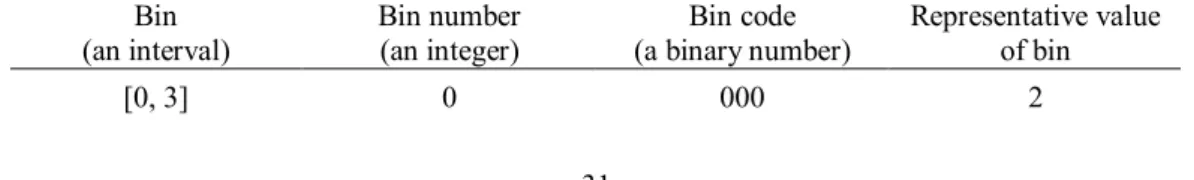
Table I. Bins, bin numbers, bin codes, and representative values of bins used in this study.
Bin (an interval)
Bin number (an integer)
Bin code (a binary number)
Representative value of bin
[0, 3] 0 000 2
[4, 7] 1 001 6
[8, 11] 2 010 10
[12, 15] 3 011 14
[16, 19] 4 100 18
[20, 23] 5 101 22
[24, 27] 6 110 26
[28, 31] 7 111 30
Table II. Statistics of experiments using a surveillance image of Fig. 4(a).
Surveillance image (480×360)
Total # of tampered pixels (tampering ratio)
PSNR of recovered image with respect
to stego-image
Total # of false acceptance pixels
Total # of false rejection pixels
Case 1 shown in Fig. 5
784
(0.45%) 45.60 90 1
Case 2 shown in Fig. 6
3895
(2.25%) 36.38 551 16
Case 3 (not shown) 8640
(5%) 29.33 2026 59
Case 4 (not shown) 17280
(10%) 23.94 4201 265
Case 5 (not shown) 34560
(20%) 17.87 8009 2411
Case 6 (not shown) 51840
(30%) 13.59 15079 9775
Case 7 (not shown) 69120
(40%) 10.42 30211 21997
Case 8 (not shown) 86400
(50%) 8.16 53353 34174
Table III. Statistics of experiments using image Lena of Fig. 8(a).
Lena (512×512)
Total # of tampered pixels (tampering ratio)
PSNR of recovered image with respect
to stego-image
Total # of false acceptance pixels
Total # of false rejection pixels
Case 1 shown in Fig. 9
2084
(0.79%) 47.00 43 12
Case 2 (not shown) 13100
(5%) 32.58 4 92
Case 3 (not shown) 26200
(10%) 25.93 87 430
Case 4 (not shown) 52400
(20%) 19.19 1169 4617
Case 5 (not shown) 78720
(30%) 14.12 8114 18866
Case 6 (not shown) 104640
(40%) 10.85 27678 42277
Case 7 (not shown) 131072
(50%) 8.52 65399 65477
Table IV. Comparison of performance of proposed method with those of [8] and [9].
Authentication
methods Pixel-level Recoverable # of correctly detected pixels out of 2084 tampered pixels
Limitation of tampering ratio
Method in [8] Yes No Around 1042 Unrestricted
Method in [9] Yes No 1996 ≦1.1%
Proposed method Yes Yes 2041 ≦10%
List of figure captions
Fig. 1. Illustration of bin code (authentication signal) generation and embedding. (a) Mapping 5-bit MSBs to a 3-bit bin code. (b) Bin codes embedded into pixels randomly selected by a secret key K.
Fig. 2. Diagram of authentication signal matching and tampered pixel marking (detail to be described in Algorithm 2).
Fig. 3. Diagram of tampered pixel repairing (detail to be described in Algorithm 2).
Fig. 4. Generation of stego-image from an input surveillance image. (a) Input image taken by a monitor. (b) Stego-image with PSNR value 37.51.
Fig. 5. Authentication result of a surveillance image taken by a monitor with tampered area.
(a) Image with modification of two car plate numbers. (b) Authentication image with noise.
(c) Final authentication image. (d) Final repairing result with PSNR 45.60 with respect to stego-image.
Fig. 6. Authentication result of a surveillance image taken by a monitor with tampered area.
(a) Image with modification of entire car plate. (b) Authentication image with noise. (c) Final authentication image. (d) Final repairing result with PSNR 36.38 with respect to stego-image.
Fig. 7. Relations of performances among tampering ratios, false tampering detection, and tampering repairing using surveillance image of Fig. 4(a).
Fig. 8. Generation of stego-image from another image. (a) Input image Lena. (b) Stego-image with PSNR 39.34.
Fig. 9. Authentication result of a grayscale image with an added flower shape composed of 2084 pixels. (a) Image with modification of a hair portion. (b) Authentication image with noise. (c) Final authentication image. (d) Final repairing result with PSNR 47.00 with respect to stego-image of Fig. 9(b).
Fig. 10. Relations of performances among tampering ratios, tampering detection, and tampering repairing using image Lena of Fig. 8(a).

![Table V. Comparison of performance of proposed method with those of [12].](https://thumb-ap.123doks.com/thumbv2/9libinfo/9650578.673935/28.892.133.759.385.551/table-v-comparison-performance-proposed-method.webp)