Development of An Environment for Distributed Colored Timed Petri Nets
Han-Pang Huang
*
Ting-Cheng Shih**
Robotics Laboratory, Department of Mechanical Engineering National Taiwan University, Taipei, TAIWAN 10674, R. 0. C.
e-mail: hphuangBw3 .me.ntu.edu. tw *Professor and correspondence addressee
**Graduate student TELFAX: (886)2-3633875
Abstract
In this paper, a distributed colored timed Petri net (CTPN) environment is proposed, based on the object- oriented concept, to create, simulate and model the distributed systems in a convenient way. In this environment, the user can construct a CTPN model easily and then simulate the model in a distributed simulator. 1. Introduction
The distributed systems are widely used in office automation, banking systems, and computer integrated manufacture. Due to the concurrency in a distributed system, Petri net is suitable for modeling the distributed system. But the lack of tools for generating Petri nets declines the use of Petri net. Therefore, an environment for Petri net modeling is proposed in this paper. In addition to a Petri net generator, a distributed Petri net simulator is also proposed. Such a simulator is useful in simulating and controlling the distributed system.
Some works on Petri net generator and simulator can be found in literature [ 5 ] . But it provided neither extensions of Petri net, such as CTPN (colored timed Petri net), nor a good simulation environment, such as Qstributed system support. Other works [13] can generate Petri net automatically by providing the description of the system and then run simulation based on the generated model. This method is useful only for some particular and pre-defined systems because the format of the system description is pre-defined. Our work will lay emphasis on
the generation of CTPNs and distributed simulation environment.
In this paper, we develop an environment for modeling and monitoring distributed systems based on a Petri net generator and simulator. Such a Petri net simulator can help users to create and modify Petri nets quickly, and
a
simulator can help users to understand and analyze the system modeled by Petri net. After modeling and analyzing the system by Petri net, one can use Petri net to control and monitor the system. In a distributed Petri net environment, it is necessary to control and0-7803-4778-1 /98 $10.00 0 1998 IEEE
monitor sub-nets in other computers 2 Distributed Systems and CTPN
A distributed system is a system with many processing elements and many storage devices, connected together by a computer network. A distributed system has to be capable of parallel execution and of kecping operation in case of single-point failures. The communication between the processing elements is done through interconnection hardware which allows processes running in parallel to communicate and synchronize.
The CTPN (Colored Timed Petri Net) [7-10,121 consists of macro transitions and comnnunication places.
A macro transition represents a Petri net model for a sub- system of the system. Communications between Petri net and its macro transitions are done by communication places. Different system architectures will use different types of communication places. The system in a hierarchical form will have pitch-up, pitch-down, catch- up and catch-down places to communicate with its upper
or lower sub-systems [%lo]. The systeim in a distributed form will have only pitch and catch places to send and receive tokens from other systems.
In an object-oriented approach [l-61, the object model encompasses the principles of abstractilon, encapsulation, modularity, hierarchy, typing, concurrence, and persistence, and the system is viewed as the interaction of several objects. These objects communication one another through defined messages. The objects with the same state space and behavior are grouped into the same class. In other words, the elements of the object model is object, message and class.
The CTPN with object-oriented approach is a suitable modeling representation of a distributed system because a Petri net model has properties, such as imodularity (macro transition), communication interfaces (communication places), concurrency and parallel events, that meet the propemes of the distributed systems.
3. Distributed CTPN Generator
By using object-oriented method,
the:
requirements and523
functions of the distributed CTPN generator to abstract objects and classes for the system should be first explored. Each class has essential attributes and methods to perform its role in the whole object model. There are certain relations between objects and classes, including generalization-specialization relation (inheritance), whole-part relation and object connection (message connection). These relations are also important in the object model. Finally, there come up with following classes : CCTPNObj, CPlace, CTran, CComPlace, CMacroTran, CArc, C N " e t , CCTPNDoc and CCTPNView. CCTPNObj is the superclass of all CTPN objects and has the basic attributes and behaviors of CTPN objects. CPlace, CTran and CArc are basic CTPN objects which constitute the net. CMacroTran is derived from Ctran and is used
as
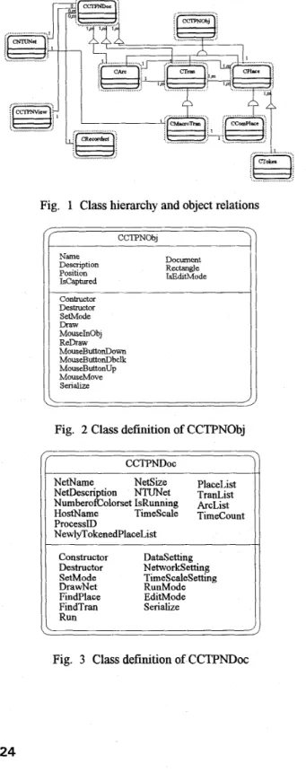
the macro transition. CComPlace is derived from CPlace and is used as the communication place. CCTPNDoc contains the all objects which compose the whole net. It has some data structures for storing those CTPN objects of the net. CCTPNView provides the functions of display and graphic user interfaces. C N " e t provides the functions of the network communication. CRecordset provides the functions of database accessing. Detailed attributes, methods and relations of classes can be found in Fig. 1- Fig.3.The PN generator can help us to construct a Petri net model easily. The graphic
user
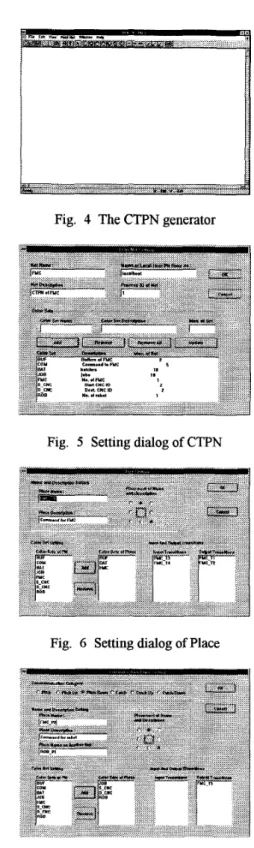
interfaces are used toconstruct a Petri net dn-ectly. User can select a place or a transition then put it on any position he wants and he can double click the object to input its attributes. Then he can connect place and transition by various kinds of arcs. This work constructs not only PNs but also CTPNs. The Merence is that color sets can be assigned to each place and transition to give them suitable attributes. These attributes are very important when CTPN is executed. Another difference is that some network parameters can be assigned to communication places and macro transitions so that they can transfer tokens to other communication places on different computers. Because the generator is based on a distributed environment, one can create all Petri nets required on one computer then transfer them to appropriate computers for simulating or controlling The CTPN generator and some setting dialog boxes are shown in Fig. 4
-
Fig. 8.4. Distributed
CTPN
SimulatorWhen a Petri net is growing larger and larger, analytic techniques, such
as
reachability tree and matrix equations, become unrealistic because the complex tree and huge matrix increase the difficulty of analysis and calculation. The problem is even harder when applying CTPNs because the input matrix and output matrix of CTPN not only are two dimensions but also have the third dimension to represent different colors. Another way to analyze Petrinets is a non-analytic method
--
simulation. By simulating a Petri net, some necessary conditions for certain properties of the net can be found and these will be helpful to understand and control this system.,([-&-;...);
1
... I I Il
-'i!
! ,,\ I .... zl ... i-r?
-.L;l.(r""t am r G j " ... ... '4 JFig. 1 Class hierarchy and object relations CCTF"0bJ Name Desaiption Position Iscaptured Document Rectangle IsEditMode Contructor Destructor SetMode Draw MouseInObj ReDraw MouseButtonDown MouseButtonDbclk MouseButtonUp MouseMove Serialize
Fig. 2 Class definition of CCTPNObj
NetDescription NTUNet TranList NumberofColorset IsRunning kcList HostName Timescale Timecount ProcessID NewlyTokenedPlaceList Constructor Destructor SetMode DrawNet DataSetting Networksetting Timescalesetting RunMode Edit M o d e Serialize Findplace
Fig. 3 Class definition of CCTPNDoc
Fig. 4 The CTPN generator
Fig. 5 Setting dialog of CTPN
Fig. 6 Setting dialog of Place
Fig. 7 Setting dialog of communication place
Fig. 8 Setting dialog of transiiion
3..n
Fig. 9 The CTPN simulator
The simulation environment is based on a network of computers so that each Petri net on @(:rent computers can communicate and transfer information between each other. The CTF" simulator is shown in Fig. 9.
Network Protocol and Architecture
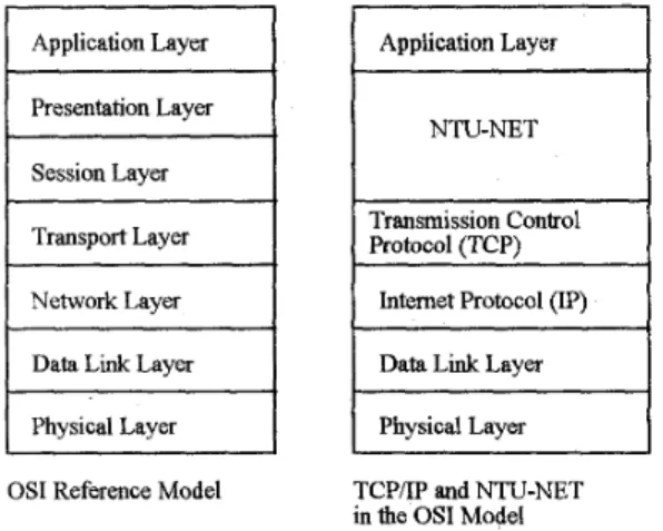
Our network is based on NTU-NET [12], a well developed network protocol. NTU-NET is stacked on TCP/IP. TCP/IP is the most popular protacol on different platforms and is located between the presentation layer and session layer in the seven layers of international standard organization (BO) reference model for open system interconnection (OSI), as shown in Fig. 10. NTU- NET provides five network communication objects with Merent priorities. They are alarm, conclition, message, mail and file objects and their priorities are from high to low. By using this protocol, computers can transfer different information according to its priority The emergent information like alarm can be sent first and the condition of each net or tokens transferred between nets will be sent later if an alarm occurs. It is im efficient way to communicate especially when the network is busy.
Upon receiving a token by a pitch place, a pitch-up place or a pitch-down place the simulatolr will send the token information to the corresponding places in the remote net which is defined by a macro transition in the local net. Similarly, when a catch place, either catch-up place or catch-down place, removes a token, the simulator will inform the related nets to remove the tokens in the corresponding places. These communications used for transferring tokens are the most frequent communications
during the net is running. In addition, there are some communications for querying states of computers, as shown in Fig. 11.
Application Layer Application Layer Presentation Layer Session Layer Tran. Name
I
Transmission ControlI
TransportLayerI
I
Protocol (TCP) Priority of Tran. I-
. . 11
NetworkLayerI
Physical LayerOS1 Reference Model TCPAP and NTU-NET
in the OS1 Model Fig. 10 Architecture of "U-NET
I I ,
..., j; ...._._.._...._... ....-..
Fig. 11 Communications between nets Data Format
There are some data tables required in simulation environment, especially those system-dependent data. The developed CTPN generator
and
simulator have provided some dialog boxes for data setung but other data will be set during run time. The data format is defined by the following tables : transition time table, conflict transition priority table, colorset priority table, initial tokens table and inputloutput colorset mapping table, These tables are very important as executing CTPN. Transition time table assigns each timed transition a firing time according toMerent color values. Conflict transition priority table assigns the priority of transitions which may be conflict in run time. Colorset priority table assigns each color value a priority to decide which color value and associated token can enable transitions. Different row of this table
represents different main color that dominates the execution of CTPN. Initial tokens table assigns some tokens to places when the system starts. This is the initial conditions of the CTF". Inputloutput colorset mapping table is used to map input colorset value to different output colorset value for each transition. T h ~ s means that some attributes are added to tokens after the transition is fired. The columns and types of each table are shown in Fig. 12. When simulation is complete, a text output file, which records the events including adding or removing tokens, firing transitions and sending or receiving tokens in communication places, and the occurred time events, will be created. By analyzing this output file, the behaviors and the properties of the system can be obtained. Execution Procedure
After creating the CTPN by graphical generator, The user can change to run mode to execute the C V N . Firstly, the user must check the network status to ensure the related computers whose name are defined in macro transitions are running the proposed environment. If they are still in edit modes, change their modes to run modes. If all computers are ready to run, the net can be executed. Secondly, the initial conditions and other essential data of the net should be set according to data tables mentioned in the last section. After setting initial conditions, some places will have tokens. Then the CTPN is executed according to the following steps.
Translhon Tune Table
I Tran.Name I TuneColorset TuneforValuell 0 I Tune for ValueN I Conflict Transition priority Table
Fig. 12 Data format (columns of tables)
1. For each place which receives tokens, check each output transition of this place whether it is enabled for
certain colorset values.
2. After checking all output transitions of the place, if there are conflict transitions which can be enabled by the same colorset value, compare the priority of conflict transitions to decide which transition can be fired.
3.
If
more than one colorset values can enable the transition, compare the priority of colorset value to decide which colorset value can enable the transition.4. If a transition can be fired, call the firing procedure
of the transition to perform its firing. For immediate transition, dispatch tokens to its output place immediately 526
after firing.
5 . After a transition was fired, some tokens were
hspatched to output places of the transition, and these places will check its output transitions as step 1.
6. If no transitions can be enabled, several situations can occur. One is that the system has finished all works so
that no more actions are needed. Another situation is that some communication places are waiting for tokens dispatched from other nets. The last possible situation is that some transitions may be deadlocked and result in no token dispatching. The proposed simulation environment can detect the above situations and inform users to or not stop simulation.
Jinplemeatation
The work is developed on Microsoft Windows NT
version 3.0 with Microsoft Visual C t c version 2.0.
Windows NT is a network operating system and provides TCP / IP protocol so that the NTU-NET communication protocol can be easily applied.
Database Connection
ODBC (Open database connectivity) is used for database connection. ODBC provides not only SQL (Structured query language) but also the interface between C language and SQL database. Thus, the proposed environment can connect any database which provides an ODBC driver,
as
shown in Fig. 13. It is flexible and efficient because neither a specific database nor redundant codes for supporting different databases is required. The database can be attached to the local machine or the remote machine depending on system requirements and environment.Interface among Modules
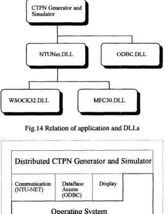
The functions of NTU-NET and ODBC are packed as DLLs (dynamic linking library) and provide a well defined application programming interfaces. In other words, the capabilities of network communication and database connection will be embedded in the application program by calling these interface, as shown in Fig.14. The architecture of the distributed CTPN environment is
shown in Fig. 15.
(ODBC)
ll
I
Fig. 13 Data sources selection
I
CTPN Generator andI
SimulatorI--
1 ODBC.DLLvu
A-[
WSOCK32.DLLJ
i/
MFC30.DLL]
Fig. 14 Relation of application andl DLLsDistributed CTPN Generator and Simulator
Fig. 15 Distributed CTPN Environment architecture 5. Simulation
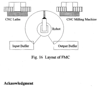
The simulation case is a x;MC in the automated factory of Department of Mechanical Engineering of National Taiwan University. This
FMC
has a robot,a
CNC lathe, a CNC milling machine and two input / output buffers. The robot is used to transfer parts among the CNC lathe, CNC milling machine and buffers. The CNC lalhe and milling machine are used to machine jobs. In this automated factory, the parts in the input / output buffc:rs are removed by an AGV (automated guided vehicle), but the AGV will not present in the FMC. Hence, the buffers are assumed to be large enough to contain all parts. The layout of the FMC is shown in Fig. 16.6. Conclusions
In this paper, a distributed CTPN environment including a CTPN generator and a CTPN simulator is proposed. Such an environment can help users to create and simulate CTPNs of the systems maire easily. The functions of the distributed CTPN environment has been proven in the FMC simulation. These functions, including
using graphic user interface to create a CTPN, network communication, database access and distributed simulation environment, help us to construct the system model and to analyze the system by simulation more easily. With the object-oriented concept, the effort of modifying
a
pre-constructed C'I'F" is easy.CNCLathe
/
\
CNC Milling Machine Input BufferRobot
Fig. 16 Layout of FMC
Acknowledgment
This work is partially supported by National Science Council, Taiwan, R.O.C. under grant number NSC 87- 2622-E-002-004.
References
[l] S . Adiga, Object-Oriented Sofhvare for Manufacturing Systems, London: Chapman &Hall,
1993.
[2] G. Booch, Object-Oriented Analysis and Design with
Applications, 2nd edition, Redwood City CA: BenjamidCumming Publishing Company, Inc.,
1994.
131 A. Camurri, P. Franchi and M. Vitale, "An Object- Oriented Approach to High-Level Petri Nets,"
Microprocessing and Microprogramming, Vol. 3 5, [4] F. DiCesare, M. Gile and P. Kulp, "An Object Oriented Graphwal Tool for Creating and Editing Petri Nets," Int. Con$ on Computer Intergrated Manufacturing and Automation Technology, 1994.
[5j H. Fleischhach and U. Lichtblau, "MOBY
-
A Tool for High Level Petri Net with Objects," Proceedings ofthe IEEE Int. Con$ on System, Man and Cybernetics, Vol. 4, pp. 644
-
649, 1993.[6] C. R. Glassey and S . Adiga, Berkeley Library of
Objects for Control and Simulation of N0.1, pp. 213
-
210, 1992.Manufacturing, MA: Addison-Wesley Publishing Company, 1990.
[7] H.P. Huang and P.C. Chang, "Specification, Modeling and Control of a Flexible Manufacturing Cell," Int.
J. Production Research, Vol. 30, No. 11, pp. 2515- 2543, 1992.
[SI H.P. Huang and Y.H. Tseng, "Modeling and Graphic Simulator for Integrated Manufacturing Systems,"
Intelligent Automation and Soft Computing, Vol. 1, [9] C.H. Kuo, H.P. Huang, "Colored Timed Petri Net Based SPC and Fault Duagnosis to FMSs," IEEE
Intl. Con$ on Robotics & Automation, New Mexico, Vol. 4, pp.2741-2746, April, 1997. [lo] C.H. Kuo and H.P. Huang, "Dispatching and
Simulation for Highly Model-Mixed Automotive Plants," Proc. Int. Conference on Automation
Technology, Taiwan, Vol. 1, pp. 423-430, 1996.
[ 111 L.R. Lin, H.P. Huang, "Real-Time Networking for the Implementation of CIM," The 4fh Intl. Con$ on Automation Technology, Taiwan, 1996.
[12] S . S . Lu and H.P. Huang, "Modularization and Properties of Flexible Manufacturing Systems," in
Advances in Factories of the Future, CIM and Robotics (edited by M. Cotsaftis and F. Vernadat), Amsterdam: Elsevier, pp. 289-298, 1993.
[13] C. T. Shen, "Automatic Petri-Net Generator for Modeling and Scheduling of Flexible Manufacturing Cell," Master Thesis, Dept. of Information Engineering, National Taiwan University, 1995.