doi:10.6342/NTU201602172
國立臺灣大學工學院化學工程學系 碩士論文
Department of Chemical Engineering College of Engineering
National Taiwan University Master Thesis
探討錳鐵氧化物超高電容器 在有機系電解液中的速率表現 Study on Rate Performance of MnFe
2O
4with Organic Li-Ion Electrolyte
錢人豪 Jen-Hao Chien
指導教授:吳乃立 博士 Advisor: Nae-Lih Wu, Ph.D
中華民國 105 年 7 月
July, 2016
doi:10.6342/NTU201602172
I
doi:10.6342/NTU201602172
II
致謝
“生平初度的怒潮,已經漸次的消翳,只剩有疏鬆的海砂中偶爾的迴響,更有殘 缺的貝殼,反映星月的輝芒。”
−徐志摩 <<北戴河海濱的幻想>>
海平面遠方開始陰霾,我輕闔了眼簾,獨坐薑黃的沙灘上,迎著徐徐地海風,
只見晚霞的餘赭,紅潤了無邊的天際。岸邊停泊的小船隨著海潮的波紋而盪漾,
我的心情,卻猶如晶瑩剔透的水面,唇邊的一抹微哂,早已道盡了腦中的千頭萬 緒。
在不盡蟬吟的夏夜,我撐起了桅杆,順著灼熱的南風揚帆啟航,帆布的間隙,
倒映了灘邊閃爍的燈火,伴隨著水波拍岸的聲音,漸漸地愈趨朦朧。遠航的開端 總是如此平靜,平靜中容不下一絲聲響,我屏住呼吸,緩緩的輕轉木製的船舵,
展開了一段名為化工之旅的遠颺。
旅途的過程充滿了各種滋味,時而晴空萬里,時而細雨綿綿,偶有慌張,偶 有驚奇,一路上最感謝我的老師、碩班旅程的北極星−吳乃立老師,總是充滿耐 心地教導我作實驗的方法及邏輯,訓練我在思考問題時回歸最基本的知識與概念,
面對人生的挑戰時,給予我最溫暖的關心和建議,然而這兩年的化工之旅,著實 添了老師不少麻煩,謝謝老師的包容與教誨。也特別感謝工研院材化所的吳弘俊 博士及方家振博士對於我的碩士論文的提點,讓這篇論文更趨完備。
抬頭仰望,靜謐中點綴了滿天星斗的眨眼,就好像在 EML 的兩年,每一位 學長姐與學弟妹點點滴滴的陪伴,在歡笑中不失溫馨,效率中也不失感動。感謝 阿昀學長,從你身上我學會了勇敢,也特別感謝你教我測粉體導電度,那些和你 跑工研院的日子,現在回想還是十分懷念。感謝美麗氣質的大美女心惠,雖然我 們常常逗你生氣,但大方的師姐總是寬大為懷地原諒我們,希望未來有機會我們 能在上海再一起血拚。外表正經內心澎湃的神人洋洋學長,謝謝你教導了我很多 基本的觀念和實驗技巧,和你討論實驗總是獲益良多,也謝謝你給我的鼓勵,讓 我在死巷中找到了出口。認真負責的培培,還記得剛進實驗室的時候你都不說話,
讓我甚是擔心,而如今卻能看到你的活潑開朗,我實在覺得非常欣慰。外向「大」
方的羅師姐,你從馬師姐畢業之後一肩扛起了在實驗室被大家逗的任務,雖然我
doi:10.6342/NTU201602172
III
常開你玩笑,但是謝謝你在我需要幫忙時總是第一個伸出援手。學識淵博的川哥,
和你在 415 共事的日子充滿了各種歡笑,希望你在美國的實驗順利、paper 連發。
正義魔人忠憲,你是一個坦率又認真的學弟,未來實驗室的正極就靠你了。效率 哥建廷,做任何事總是有條不紊,相信你一定前途無量。東北大俠李洋,滿天都 精神飽滿充滿幹勁,調皮的學弟們就交給你好好整治了。實驗室室草秉逸,雖然 你都沒有把我當成學長,但是還是謝謝你這一年幫我的忙,415 的美好未來就全 權交給你囉。好動聒噪的彥丞,有你在我身邊當小跟班,做起實驗總是十分踏實,
希望你可以好好將超高電容發揚光大。積極老實的聖翔老大,相處久了卻覺得你 童心未泯,沒有你在我耳邊吵鬧的日子,我想我可能沒辦法很快習慣。也感謝細 心的郁婷學姐,提點我各種事務的小細節。感謝信良、彥伯、孝安諸位超高電容 的前輩,當我遇到不解的難題時不吝給我寶貴的建議。正氣凜然的揚恆,從你身 上我學會了好多書本以外的知識,謝謝你做我的人生導師。萬人迷 Vilko、老鼠 剋星 Erwin、德國紳士 Lukas、憨厚內向的哲凱以及社交天王 Baskar,和你們短 暫的相處時光,著實璀璨了我的碩士生涯。貼心的專題生一格、臻卓,即使只有 短短半年,就足以感受到妳們的熱情。實驗室的新成員玉祥、昌恩,同為棒球痴、
棒球狂,卻沒有機會跟你們 KGB 真的滿可惜的,祝福你們實驗都能順利上手囉。
也謝謝曉婷姊,替我們處理繁複的報帳事宜。
致一葦、郁涵,我的台大好姊妹們,我想我一定會很懷念我們一起聊天聚餐 講八卦的瘋狂歲月。我的清大好哥們冠群、家佑、品淞、俊緯、岳佑、詠傑,雖 然分隔兩地,但是真摯的關心卻不曾中斷,有機會的話,還想跟你們好好打一場 球。清材第五帥傳穎、潮男興宇,來台北時都還記得找我吃飯,吾人真的甚為感 動。台大化工系壘伙伴小魚、獻隆、文祺、雲皓、昇育、朝翔、羽飛,和你們一 起征戰慢壘聯盟的日子真的十分過癮,可惜我們沒有一起拿個獎盃阿。
我最摯愛的家人,無怨無悔的做我最堅強的後盾,讓我沒有後顧之憂地完成 學業。可愛又善解人意的明恩,謝謝妳在我最忙碌的歲月中默默地陪伴,妳的鼓 勵一直都是我持續向前的動力。
夕陽喚醒了海波,潮餘的斑痕也漸褪了色,回首這趟旅程的點滴,若不是有 許多貴人無私的鼓勵與協助,我將無法順利走到終點線,謹以此篇論文,獻給我 深愛的每一個人。 人豪 謹識 丙申年 仲夏
doi:10.6342/NTU201602172
IV
摘要
近年來有愈來愈多帶有偽電容行為的金屬氧化物超高電容器被開發出來,而 在我們過去的研究中,揭示了奈米級的結晶型錳鐵氧化物是目前唯一一種在水系 電解液及有機電解液中均能表現偽電容的氧化物,此發現開啟了高能量密度的有
機系 MnFe2O4超高電容器的研究大門。
在本論文的第一部份,利用共沉法成功地製備 MnFe2O4/CB 複合材料,且該
材料在 NaCl 水溶液中之電容行為亦被測試,研究結果顯示在不同的燒結溫度下,
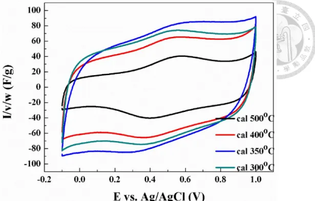
MnFe2O4/CB 在經過 350°C 的高溫煅燒後有最大的比電容值 (63.1 F/g-composite)。
在第二部份中,我們嘗試改變過渡金屬在錳鐵氧化物中的比例,發現在有機 系電解液中,錳鐵氧化物的比電容值會隨著錳濃度的增加而上升,並且透過有機
電解液的使用,成功地提升 MnFe2O4/CB 超高電容器的能量密度,在功率密度為
413 W/kg 的條件下,其具有 59.6 Wh/kg 的能量密度,即使功率密度提高至 16809 W/kg,仍具備 24.3 Wh/kg 的能量密度。而錳鐵氧化物的電容量和工作電位區間 的關係亦被檢視,在不斷擴大工作電位範圍的情況下,鋰離子能與更內部的錳鐵 氧化物發生電荷交換的法拉第反應,因此貢獻出更大的偽電容值。
另外,透過稀釋過渡金屬的濃度,錳鐵氧化物會在較低的燒結溫度下便具有 尖晶石結構,不僅如此,較低的煅燒溫度也抑制了錳鐵氧化物的高溫聚集的現象,
並強化了 MnFe2O4/carbon 在高速率下的電容表現,在電位掃描速率為 100 mV/s
的條件下,仍有高達 60%的電容保持率,由於我們過去的研究成果顯示,錳鐵氧
doi:10.6342/NTU201602172
V
化物的偽電容主要由佔據尖晶石結構之四面體位置的錳所貢獻,因此尖晶石結構 的形成對後續錳鐵氧化物的偽電容表現具有極大的影響。
最後我們用一個較精確的方法來決定超高電容器的工作電位區間,其中,以 防止過大漏電流產生的觀點,定出電壓上限,另一方面,透過將氧化物電極的能 量密度最大化,決定電壓下限。
關鍵字: 超高電容器、MnFe2O4、有機系電解液、速率表現、能量密度、稀釋
doi:10.6342/NTU201602172
VI
Abstract
An increasing number of metal oxides exhibiting pseudocapacitive behaviors have been investigated in recent years. We have discovered a nanocrystalline oxide material having the formula of MnFe2O4 that have so far been the only oxide electrode showing pseudocapacitance in both aqueous and organic Li-ion electrolytes. The discovery of this material has opened up the possibility of setting up a high voltage pseudocapacitors of substantially enhanced energy density over the state-of-the-art organic supercapacitors.
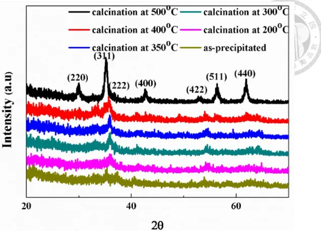
In the first part of the thesis, MnFe2O4/CB composite materials have been synthesized via coprecipitation method and followed with a thermal calcination. The electrodes of that composite were tested for the capacitive behaviors in aqueous NaCl solution. For different calcination temperatures, the electrode using MnFe2O4/CB which calcined at 350°C exhibits 63.1 F/g-composite under 10 mV/s scan rate and possesses the largest capacitance compared to the others.
Second, we have explored the spinel-based nanocrystalline ferrite electrodes with various transition metal compositions in organic Li-ion electrolyte. The results indicated that an increment in specific capacitance could be observed with increased concentration of manganese ion. Moreover, an enhanced energy density of MnFe2O4/CB supercapacitor could be obtained by applying the organic Li-ion electrolyte. It displays a substantially higher energy density of 59.6 Wh/kg at a power density of 413 W/kg. Even at a high power density of 16809 W/kg, it still delivers an energy density of 24.3 Wh/kg. The relationship between capacitance and potential
doi:10.6342/NTU201602172
VII
window had also been examined and it was found out that more lithium ions could react with the inner surface of manganese ferrite with broader voltage window and thus resulted in a relatively larger pseudocapacitance.
Enhanced rate performance was derived by diluting the concentration of transition metals. The capacitance retentions of MnFe2O4/carbon electrodes are found to be above 60% under 100 mV/s. The superior capability of delivering rather high capacitance under high-power conditions is attributed to the spinel structure formed after lower temperature calcination. Based on our previous study, the pseudocapacitance is predominantly arising from the charge-transfer reaction at the tetrahedral sites of the spinel, balanced by the insertion of cations from the electrolyte.
Besides, the operation voltage window was carefully determined in view of leakage current for the upper voltage limit. On the other hand, the lower voltage limit was selected to maximize the energy density of the spinel oxide electrode.
Keywords: Supercapacitor, MnFe2O4, Organic Li-ion electrolyte, Rate performance, Energy density, Diluted concentration
doi:10.6342/NTU201602172
VIII
Table of Contents
致謝 ... II 摘要 ... IV
Abstract ... VI Table of Contents ... VIII List of Tables ... XII List of Figures ... XIII
Chapter 1 Introduction ... 1
1.1 Background ... 1
1.2 Motivations and Objectives ... 2
Chapter 2 Theory and Literature Review ... 3
2.1 Introduction to Electrochemical Capacitors ... 3
2.1.1 Introduction to Energy Storage Devices ... 3
2.1.2 Classifications of Electrochemical Capacitors ... 6
2.1.3 Models and Theory for Electric Double Layer ... 8
2.1.4 Electrochemical Characteristics of Capacitors ... 12
2.2 Development of Electrochemical Capacitors ... 14
2.2.1 Electrode Materials ... 14
2.2.2 Electrolyte ... 17
2.3 Introduction to Manganese Ferrite, MnFe2O4 ... 19
2.3.1 Structure and Characteristics ... 19
2.3.2 Synthesis and Development on Supercapacitors ... 23
doi:10.6342/NTU201602172
IX
Chapter 3 Experimental ... 25
3.1 Synthesis of Electrode Materials ... 25
3.1.1 MnFe2O4/Carbon Black Composite Materials ... 26
3.1.2 MnFe2O4/Carbon Nanotube Composite Materials ... 27
3.1.3 MnFe2O4/Carbon Composite Materials Fabricated by Diluted Concentration of Transition Metals ... 27
3.2 Analysis and Characterization ... 31
3.2.1 Phase Identification ... 31
3.2.2 Microstructure Characterizations ... 33
3.2.3 Surface Area Analysis ... 33
3.2.4 Resistivity of Powder-like Mixture ... 34
3.3 Electrochemical Characterizations ... 35
3.3.1 Preparation of Electrodes ... 35
3.3.2 Cyclic Voltammetry ... 36
3.3.3 Chronopotentiometry ... 37
Chapter 4 Investigation on Capacitive Performance of Ferrite Supercapacitors ... 39
4.1 Introduction... 39
4.2 Material Characterizations ... 41
4.3 Operating Characteristics of Manganese Ferrite/ Carbon Black Supercapacitors in Aqueous Electrolyte ... 47
4.3.1 Investigation on MnFe2O4/CB Composite Materials ... 47
4.3.2 Investigation on Mn1-xFe2+xO4/CB Composite Materials ... 49
4.4 Investigation on Electrochemical Behaviors of
doi:10.6342/NTU201602172
X
Mn1-xFe2+xO4/Carbon Black Supercapacitors in Organic Li-ion Electrolyte ... 54
4.4.1 Effect on rate performance by replacing NaOH(aq) with LiOH(aq) in the coprecipitation process ... 54 4.4.2 Rate performance of Mn1-xFe2+xO4/CB electrode under high potential….………55 4.4.3 Rate performance of Mn1-xFe2+xO4/CB electrode over wider potential window ... 56 4.4.4 Enhanced Energy Density of MnFe2O4/Carbon Black Supercapacitors ... 57 4.4.5 Cycling Stability of MnFe2O4/Carbon Black in Organic Li-ion Electrolyte ... 57 4.4.6 Relationship between Capacitance and Potential Window of MnFe2O4/Carbon Composite Materials ... 58
4.5 Electrochemical Performance of MnFe2O4/Carbon Nanotube Synthesized by Impregnation Method ... 71
4.5.1 Physical Analysis of MnFe2O4/CNT Composite Materials ... 71 4.5.2 Electrochemical Properties of MnFe2O4/CNT Composite Materials………...……72
4.6 Enhanced Rate Capability of MnFe2O4/Carbon Composite Materials Fabricated by Diluted Concentration of Transition Metals………76
4.6.1 Physical Analysis of MnFe2O4/Carbon Composite Materials ... 76 4.6.2 Crystallinity Effect on Electrochemical Property ... 84
doi:10.6342/NTU201602172
XI
4.6.3 Electrochemical Characterization of MnFe2O4/Carbon Composite Materials ………..84
4.7 A precise way to determine the operation voltage window .... 94 Chapter 5 Conclusions and Outlook ... 98 References ... 100
doi:10.6342/NTU201602172
XII
List of Tables
Table 2-1. Metal ion distribution and saturated magnetization at 0 K for simple
ferrites with spinel structure [66]. ... 22
Table 3-1. List of chemicals used in this study. ... 25
Table 3-2. Standard powder diffraction data based on Cu Kα radiation. ... 32
Table 4-1. List of specific capacitance of composite calcined at 350°C; (10mV/s) ... 53
Table 4-2. List of outer surface capacitance and total capacitance derived by fitting ... 70
Table 4-3. Average crystallite size of MnFe2O4 in various composite materials ... 82
Table 4-4. Average crystallite size of MnFe2O4/CB with/without dilution ... 82
Table 4-5. List of the specific surface area of pristine carbon and MnFe2O4/carbon composite materials. ... 83
Table 4-6. List of carbon content in various composite materials. ... 83
Table 4-7. List of tap density. ... 89
Table 4-8. List of volumetric capacitance. ... 89
doi:10.6342/NTU201602172
XIII
List of Figures
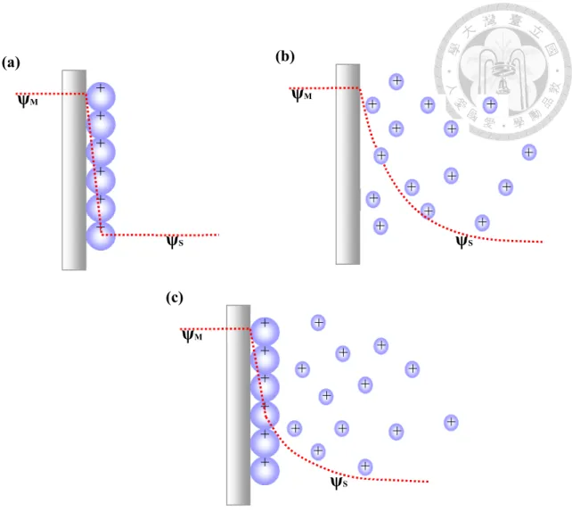
Figure 2-1. Schematic illustration of a typical electrochemical capacitor. ... 5 Figure 2-2. Ragone plot of various energy storage devices. ... 5 Figure 2-3. The construction of the double layer along with the corresponding potential profile across the double layer region, where IHP and OHP are the inner and outer Helmholtz plane, respectively... 7 Figure 2-4. Schemes of the electric double layer: (a) the Helmholtz model; (b) the Gouy-Chapman model; (c) the Stern model. ... 11 Figure 2-5. Voltage input of the cyclic voltammetry. ... 13 Figure 2-6. The structure of ferrite materials. (a) ball-and-stick model, and (b) polyhedral model with alternating octahedral and tetrahedral-octahedral layers. ... 21 Figure 3-1. The flowchart for synthesis of MnFe2O4/CB via co-precipitation process.
... 28 Figure 3-2. The flowchart for synthesis of MnFe2O4/CNT. ... 29 Figure 3-3. The flowchart for synthesis of MnFe2O4/carbon composite material fabricated by diluted concentration of transition metals. ... 30 Figure 3-4. The configurations of the electrochemical instrument. (a) a three- electrode cell (aqueous electrolyte system) and (b) a two-electrode cell (organic Li- ion electrolyte system). ... 38 Figure 4-1. TEM picture of MnFe2O4/carbon black composite powders... 43 Figure 4-2. SEM micrograph of pristine CB (XC72). ... 43 Figure 4-3. SEM micrographs of ferrites: (a)MnFe2O4/CB before calcination;
(b)MnFe2O4/CB calcined at 350°C; (c)MnFe2O4/CB calcined at 500°C. ... 44 Figure 4-4. X-ray diffraction patterns of coprecipitated MnFe2O4/carbon black
doi:10.6342/NTU201602172
XIV
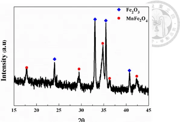
powders calcined at different temperatures. ... 45 Figure 4-5. X-ray diffraction pattern of coprecipitated single-phased MnFe2O4
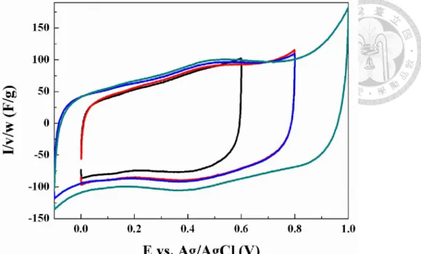
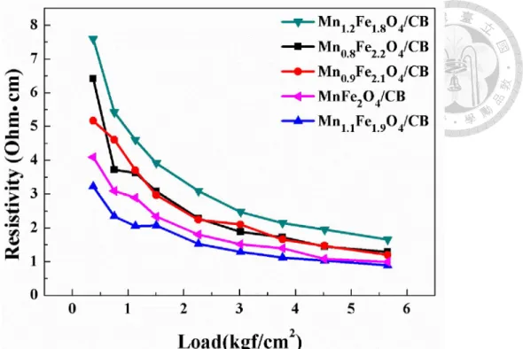
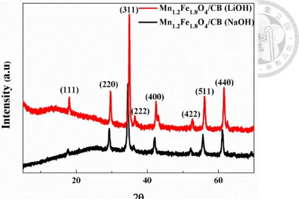
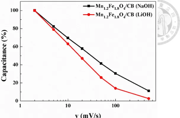
powders calcined at 600°C. ... 46 Figure 4-6. X-ray diffraction pattern of the coprecipitated MnFe2O4/carbon black powders calcined at 600°C. ... 46 Figure 4-7. Cyclic voltammograms of the coprecipitated MnFe2O4/CB composite powders (weight ratio = 7:3) calcined at different temperatures under 10mV/s. .... 50 Figure 4-8. Comparison of rate performance between MnFe2O4/CB with different calcination temperatures. ... 50 Figure 4-9. Cyclic voltammograms of MnFe2O4/CB with gradually enlarging voltage window (calcined at 350°C for 2 hours). ... 51 Figure 4-10. X-ray diffraction patterns of Mn1-xFe2+xO4/CB (x= -0.2~0.2) composite powders after calcined at 500°C for 2 hours. ... 51 Figure 4-11. Powder resistivity of Mn1-xFe2+xO4/CB (x= -0.2~0.2) after calcined at 350°C for 2 hours. ... 52 Figure 4-12. Cyclic voltammograms of the coprecipitated Mn1-xFe2+xO4/CB (weight ratio = 7:3) after calcined at 350°C for 2 hours (Scan rate: 10mV/s)... 52 Figure 4-13. X-ray diffraction patterns of Mn1.2Fe1.8O4/CB using different basic solution in the coprecipitation process (calcined at 500°C for 2 hours)... 60 Figure 4-14. Cyclic voltammograms of Mn1.2Fe1.8O4/CB using NaOH(aq)/LiOH(aq) in the coprecipitation process (calcined at 350°C for 2 hours) (scan rate: 10mV/s). .. 60 Figure 4-15. Comparison of rate performance of Mn1.2Fe1.8O4/CB using different basic solution in the coprecipitation process. ... 61 Figure 4-16. Cyclic voltammograms of Mn1-xFe2+xO4/CB under high potential (calcined at 350°C for 2 hours) (scan rate: 10mV/s). ... 61
doi:10.6342/NTU201602172
XV
Figure 4-17. Rate performance of Mn1-xFe2+xO4/CB composite in the voltage range of 3V to 4.5V. ... 62 Figure 4-18. Normalized rate performance of Mn1-xFe2+xO4/CB composite in the voltage range of 3V to 4.5V. ... 62 Figure 4-19. Cyclic voltammograms of Mn1-xFe2+xO4/CB over wider potential window (calcined at 350°C for 2 hours) (scan rate: 10mV/s). ... 63 Figure 4-20. Rate performance of Mn1-xFe2+xO4/CB composite in the voltage range of 2.3V to 4.5V (calcined at 350°C for 2 hours). ... 63 Figure 4-21. Normalized rate performance of Mn1-xFe2+xO4/CB composite in the voltage range of 2.3V to 4.5V (calcined at 350°C for 2 hours). ... 64 Figure 4-22. Ragone plot of MnFe2O4/CB supercapacitor using different electrolyte.
... 64 Figure 4-23. Cycling stability of MnFe2O4/CB electrode in organic Li-ion electrolyte (Current density: 0.5 A/g). ... 65 Figure 4-24. X-ray diffraction patterns of MnFe2O4/CB electrode investigated before/after 10000 cycles. ... 65 Figure 4-25. SEM micrographs of MnFe2O4/CB electrode investigated before (a, b, c)/after (d, e, f) 10000 cycles. ... 66 Figure 4-26. Simulation for outer surface capacitance of Mn1.2Fe1.8O4/CB electrode (voltage window: 2.9V- 3.7V). ... 67 Figure 4-27. Simulation for total capacitance of Mn1.2Fe1.8O4/CB electrode (voltage window: 2.9V- 3.7V). ... 67 Figure 4-28. Simulation for outer surface capacitance of Mn1.2Fe1.8O4/CB electrode (voltage window: 2.7V- 4.0V). ... 68 Figure 4-29. Simulation for total capacitance of Mn1.2Fe1.8O4/CB electrode (voltage
doi:10.6342/NTU201602172
XVI
window: 2.7V- 4.0V). ... 68
Figure 4-30. Simulation for outer surface capacitance of Mn1.2Fe1.8O4/CB electrode (voltage window: 2.3V- 4.5V). ... 69
Figure 4-31. Simulation for total capacitance of Mn1.2Fe1.8O4/CB electrode (voltage window: 2.3V- 4.5V). ... 69
Figure 4-32. SEM micrographs of (a) pristine CNTs; (b) MnFe2O4/CNT composite with pre-acid-washing; (c) MnFe2O4/CNT composite without pre-acid-washing. . 73
Figure 4-33. X-ray diffraction patterns of MnFe2O4/CNT composite materials after calcination at elevated temperatures. ... 74
Figure 4-34. Cyclic voltammograms of MnFe2O4/CNT undergoing different pretreatment (scan rate: 10mV/s). ... 74
Figure 4-35. Rate performance of MnFe2O4/CNT composite materials undergoing different pretreatment. ... 75
Figure 4-36. Normalized rate performance of MnFe2O4/CNT composite materials undergoing different pretreatment. ... 75
Figure 4-37. SEM micrograph of pristine graphene oxide (GO). ... 79
Figure 4-38. SEM micrographs of (a) MnFe2O4/CB; (b) MnFe2O4/GO; ... 80
Figure 4-39. TEM micrographs of (a) MnFe2O4/CB; (b) MnFe2O4/GO; ... 81
Figure 4-40. X-ray diffraction pattern of MnFe2O4/carbon composite materials (calcination at 300°C for 2 hours). ... 82
Figure 4-41. X-ray diffraction patterns of MnFe2O4/CB composite materials calcined at different temperatures. ... 87
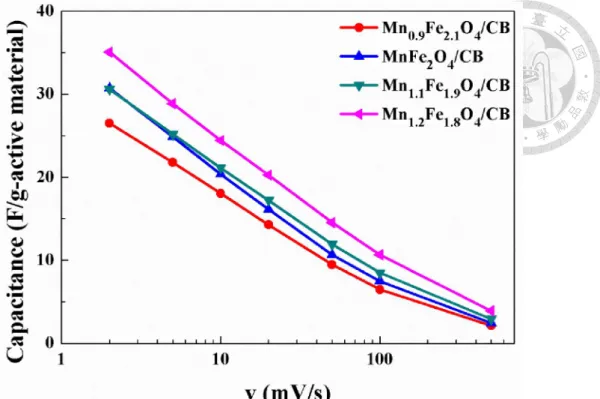
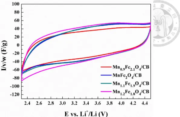
Figure 4-42. Cyclic voltammograms of MnFe2O4/CB composite materials calcined at different temperatures (scan rate: 2 mV/s). ... 87 Figure 4-43. Comparisons of cyclic voltammograms between pristine carbon and
doi:10.6342/NTU201602172
XVII
MnFe2O4/carbon. The curves have been normalized to have the same amount of carbon (Scan rate: 2 mV/s). ... 88
Figure 4-44. Cyclic voltammograms of (a) MnFe2O4/CB; (b) MnFe2O4/GO;
(c) MnFe2O4/CNT electrodes for successive increases of the potential window (scan rate: 2 mV/s). ... 90 Figure 4-45. Cyclic voltammogram of MnFe2O4/CB electrode for successively
“over” increases of the potential window (scan rate: 2 mV/s). ... 91 Figure 4-46. Comparison of cyclic voltammograms between MnFe2O4/carbon electrodes (scan rate: 10 mV/s). ... 91 Figure 4-47. Rate performance of different materials in the voltage range of 1.9V to 4.5V. ... 92 Figure 4-48. Normalized rate performance of different materials in the voltage range of 1.9V to 4.5V. ... 92 Figure 4-49. Nyquist plots of MnFe2O4/CB electrodes with/without dilution of transition metal ions ... 93 Figure 4-50. Rate performances of MnFe2O4/CB electrodes with/without dilution of transition metal ions ... 93 Figure 4-51. Chronopotentiometry of MnFe2O4/CB electrode to investigate the leakage current (Applied current: 5E-6(A)) ... 96 Figure 4-52. Evolution of leakage current of MnFe2O4/CB electrode as a function of potential. ... 96 Figure 4-53. Charging/discharging curves of MnFe2O4/CB (Applied current: 1E- 4(A)) ... 97 Figure 4-54. Evolution of average energy density of MnFe2O4/CB electrode along with decreasing lower voltage limit. ... 97
doi:10.6342/NTU201602172
1
Chapter 1 Introduction
1.1 Background
Nowadays, the demand of energy storage devices increases progressively along with the advancement of civilization. Many researches have donated much effort to develop novel devices with high capacity, long durability, low cost and eco-friendly properties for practical applications.
Electrochemical capacitor, also called supercapacitor or ultracapacitor, was found out to be one of the candidates that can meet the requirement. In view of energy density and power density, this novel device is regarded as an intermediate energy storage device between batteries and conventional ceramic capacitors. Typically, electrochemical capacitor has a substantially enhanced storage capacitance which is more than thousands of times larger than ceramic capacitors. Moreover, it possesses excellent power density around 20-100 W/kg, which is ten times more than that of batteries. As a result, these characteristics make supercapacitor extremely versatile as a stand-alone energy supply or in combination with batteries as a hybrid system.
Supercapacitors can be divided into two categories, namely electric double-layer capacitor (EDLC) and pseudocapacitor, depending on the way of storing energy. For the applications of electrode materials, carbon-based materials with high surface area are the major ones owing to the electrochemical stability. However, its lack of capability of high power delivery restricts further applications. On the other hand, pseudocapacitor possesses a much larger capacitance from the faradaic reaction. Unfortunately, many encountered problems have not been overcome yet.
doi:10.6342/NTU201602172
2
1.2 Motivations and Objectives
So far carbon-based electrochemical capacitors have been commercialized due to the excellent cyclability and abundant storage on Earth. However, low specific volumetric capacitance limits their applications for tiny electronic devices. In addition, the cost of activated carbon used in supercapacitor is around US 30000 to 50000 dollars/ton which is much higher than that of ferrites or manganese oxides. As a result, many researches have been focused on the electrochemical performances of pseudocapacitors in order to decrease the cost and meet the energy storage requirement for next generation.
Manganese ferrite (MnFe2O4) is one of the promising active materials for supercapacitor application due to its low cost, environmentally friendly, and larger operation voltage window. In 2005, our group was the first one putting much effort into exploring the pseudocapacitive behavior of manganese ferrite. The corresponding charge-storage mechanism was revealed through in-situ X-ray absorption spectroscopy.
However, most of the previous work paid much attention to the pseudocapacitive properties of MnFe2O4 in aqueous electrolyte. In order to enhance the energy density by widening potential window, organic Li-ion electrolyte is employed as an alternative in this study. In the beginning of the study, we tried to optimize the electrochemical performance of MnFe2O4/CB composite materials in aqueous electrolyte. Second, organic Li-ion electrolyte was applied and the electrochemical property of MnFe2O4/CB composites was examined. Last but not least, we devoted the attention to improving the rate capability of MnFe2O4/carbon composite materials in organic Li-ion electrolyte by diluting the concentration of transition metals and the electrochemical characteristics were investigated. The morphologies, crystal structures, and electrochemical properties of MnFe2O4/carbon have been examined in this study.
doi:10.6342/NTU201602172
3
Chapter 2 Theory and Literature Review
2.1 Introduction to Electrochemical Capacitors
2.1.1 Introduction to Energy Storage DevicesTo catch up with the requirement of technology, more economical and more efficient energy storage devices are under development. A new type of energy storage devices, namely electrochemical capacitor [1, 2], which drown much attention due to their versatile application, was developed at the end of twenty century. The concept of them, which was proposed firstly by Helmholtz in 1874, are primarily analogous to traditional ceramic capacitors. The model for charge distribution was hypothesized including two parallel sheets of charges stored oppositely on the metal surface and others on the solution side. When a voltage is applied, charges are separated at the conducting plates, and the corresponding capacitance C is determined upon:
d C A0
(2-1)
where A is the area of plates, 0, the permittivity of free space, , the relative permittivity of dielectric, and d, the thickness of dielectric layer. The improvement of this kind of capacitor is limited due to the constrained area of electrodes and the thickness of dielectric layers. As a result, the revealed capacitance of traditional ceramic capacitors could not be substantially improved. For electrochemical capacitor, which is also called supercapacitor or ultracapacitor, the corresponding dielectric layer is constructed by ions or solvent molecules with estimated thickness around several Å [3, 4]. In addition, porous or nano-sized structure with high surface area can be adopted, which can greatly
doi:10.6342/NTU201602172
4
enlarge the active sites for separated charged ions to absorb on. Therefore, electrochemical capacitor can provide a capacitance thousands times higher than a traditional ceramic capacitor. The schematic diagram of a typical electrochemical capacitor is shown in Fig. 2-1 [5].
The Ragone plot, which summarizes the comparisons of the specific power and energy of various energy storage devices, is depicted in Fig. 2-2. Traditional ceramic capacitors, providing lower specific capacitance, are able to release accumulated charges within a short period of time by storing energy in the electric field between a pair of parallel electrical conducting plates which are separated by a dielectric layer. On the other hand, batteries stand for primary energy storage devices due to the high energy density arising from the slow bulk redox reactions. However, the relatively longer charging/discharging time inhibits their high-power delivery even though the development of lithium-ion batteries and fuel cells. As a result, electrochemical capacitor comes out to be a promising energy storage device in practical applications owing to the comparable specific energy with batteries and superior specific power.
Moreover, through appropriate cell design, both the specific energy and specific power ranges for electrochemical capacitors can cover several orders of magnitude and this makes them extremely versatile as a stand-alone energy supply or in combination with batteries as a hybrid system.
doi:10.6342/NTU201602172
5
Figure 2-1. Schematic illustration of a typical electrochemical capacitor.
Figure 2-2. Ragone plot of various energy storage devices.
- - -
- -
-
- - - - - - - - - - - - - - - - - - - - - - - - - - - - -
- -
- -
- -
- -
- - -
- -
+
+ + +
+ + + + +
+ +
+ +
+ +
- - + - -
+ +
+
+ +
+ + +
+
+
+
+
+ +
+
+ -
Current collector Active
material Separator
Current collector
+
- : anion : solvated
cation Active
material
+ + +
+
+ +
- - -
-
-
-
doi:10.6342/NTU201602172
6
2.1.2 Classifications of Electrochemical Capacitors
Electrochemical capacitors can be divided into two categories depending on the way of storing energy. The first category is electric double layer capacitor (EDLC). During the charging/discharging process, no faradic oxidation or reduction is involved for the active material and the charges are stored electrostatically at the interfaces of the electrodes. The capacitance is mainly arising from the huge amount of charged ions on the surface of the electrode [5-7]. The potential profile of the electric double layer capacitor, which was proposed by Helmholtz, is depicted in Fig. 2-3.
The other category is pseudocapacitor, which involves either superficial or multi- electron-transfer faradaic reactions at the surface of the electrode between the electrolyte and active material [2]. With charge transfer, the energy stored is much higher than the traditional ceramic capacitor and the electric double layer capacitor. As a result, pseudocapacitor has attracted much more attention recently.
doi:10.6342/NTU201602172
7
Figure 2-3. The construction of the double layer along with the corresponding potential profile across the double layer region, where IHP and OHP are the inner and outer Helmholtz plane, respectively.
φ
X1
IHP X2
OHP
X1
IHP X2
OHP
solvated cation H2O molecule anion
Metal Metal
IHP OHP OHP IHP
+
-+
+ + + +
-
-
-
-
-
doi:10.6342/NTU201602172
8
2.1.3 Models and Theory for Electric Double Layer
The basic concepts of the electrochemical capacitors, mainly for electric double layer capacitors, originate from the interfacial phenomena at a charged surface. Three different kinds of models, proposed historically in the literatures, were established to simulate the charged state of a capacitor in detailed.
Helmholz model, which was proposed firstly at 1853 [3, 4], is based on the assumption that no electron transfer occurs across the electrode/electrolyte interface and only the electrostatic interactions between the ions and the electrons are involved.
This model is illustrated in Fig. 2-4 (a), which presents the charges are adsorbed on the surface of plate with two compact arrays, one at electrode surface and the other at solution side. The differential capacitance, similar as ceramic capacitors, is
d Cd V 0
(2-2)
where σ is the stored charge density and V stands for the voltage. This model is not suitable for all cases due to its simplified assumption, which supposes the charge on the electrode is confined on the surface. Therefore, deviation in capacitances from calculated value is inevitable, especially for dilute ionic solutions.
After Helmholz model, Gouy and Chapman proposed a modified theory, namely Gouy-Chapman theory, to simulate the behavior of electric double layer [8]. In this theory, thermal fluctuation of ions was taken into account rather than assuming as a compact stacking in an array near the electrode and the ions were presumed to be point
doi:10.6342/NTU201602172
9
charges in this model. Based on the combined application of the Boltzmann energy distribution equation and Poisson’s equation, a mathematical treatment of Gouy diffuse-layer model was established to describe the electric potential between ionic space charge density in the interfacial region with respect to the distance from the electrode surface:
i
i i
i T
e z z
e n dx
d
0 exp
0 2
2 (2-3)
where ψ is measured potential, ni0, bulk concentration, κ, the Boltzmann constant, T, the absolute temperature, and zi, the charge of ion i. The Gouy-Chapman model is presented in Fig. 2-4 (b). The average distance of diffuse layer is expected to depend on potential and concentration of electrolytes. As either the concentration of the electrolyte or the charge state rises, the layer becomes more compact and the capacitance increases. However, the overestimated double-layer capacitance would lead to the failure of Gouy-Chapman theory owing to the point-charge assumption, which allows the ions approach the interface arbitrarily closely. In reality, the ions have a finite size and cannot approach the interface closer than the ionic radius.
Stern model, which was proposed at 1924, came out to be a modification of the Gouy- Chapman model. A two region model was established including the inner region of the ion distribution which could be treated in terms of an adsorption process and the outer region which could be treated as a diffusing region of arbitrarily distributed ionic charges. Hence, the overall capacitance is composed of two components arranging in series, CH and Cdiff, which is the contribution of capacitance from adsorption and
doi:10.6342/NTU201602172
10
diffusion region, respectively:
diff H
dl C C
C
1 1
1 (2-4)
From this equation, we can determine the properties of double layer and its capacitance as a function of electrode potential and ionic concentration of the solution. A schematic illustration of the Stern model is presented in Fig. 2-4 (c).
Negatively charged surface was also simulated through certain model. The closest layer, regarded as Helmholtz or Stern layer, contains solvent molecules and sometimes species specifically adsorbed. The locus of the electrical centers of the specifically adsorbed ions is called the inner Helmholtz plane (IHP), while the locus of centers of solvated ions is called the outer Helmholtz plane (OHP) (Fig. 2-3), and then followed a diffusion layer extending to bulk solution.
doi:10.6342/NTU201602172
11
Figure 2-4. Schemes of the electric double layer: (a) the Helmholtz model; (b) the Gouy-Chapman model; (c) the Stern model.
+
+ +
+ + + (a)
ψM
ψS
+ +
+ +
+ + + (c)
ψM
ψS
+ +
+ +
+ +
+ +
+
+ +
+ (b)
ψM
ψS
+ +
+ +
+ + +
+ +
+ +
+ +
+ +
doi:10.6342/NTU201602172
12
2.1.4 Electrochemical Characteristics of Capacitors
The operating characteristics of electrochemical capacitors are quite different from batteries, which are believed to charge/discharge through process with ideal thermodynamic potential that is independent of the extent of accumulated charges. On the other hand, the voltage on the capacitor declines rather linearly with the extent of charge, which arises from the relation between capacitance and voltage (dQ/dV equals to 1/C).
The charging/discharging features indicate that an electrochemical capacitor has continuous variation of free energy with degree of conversion of materials. Therefore, the energy density of it is close to (1/2)CV2, calculated from integrating the V-Q profile with a voltage difference V. Besides, power density gradually declines as the accumulated charges are released.
Cyclic voltammetry (CV) is a convenient and sensitive method to distinguish the electrochemical characteristics of devices. In this measurement, the working electrode experienced a sweep of voltage linearly versus time, as depicted in Fig. 2-5. For an ideal EDLC, the voltammogram typically shows a rectangular-shape profile. For a pseudocapacitor, owing to couples of superficial faradaic reactions involved during charging/discharging, either redox peaks or humps would appear in voltammogram.
However, a rather mirror image in the CV profile could be observed due to the faster and highly reversible reactions. Moreover, the effects related to diffusion and resistance on the capacitive behaviors can be investigated by the extent of deviation in current response when the direction of sweep is switched.
doi:10.6342/NTU201602172
13
Figure 2-5. Voltage input of the cyclic voltammetry.
doi:10.6342/NTU201602172
14
2.2 Development of Electrochemical Capacitors
2.2.1 Electrode MaterialsElectrode active materials play an important role in determining the electrochemical performance of supercapacitors. Various active materials are found out to exhibit capacitive behaviors. In general, these materials can be divided into three main categories: (1) carbon-based materials; (2) metal oxides; and (3) conducting polymers.
Carbon-based materials
Carbon-based materials have attracted much attention on the applications of electric double-layer capacitors due to their high surface area (over 1000 m2/g), convenient synthesis method, non-toxicity, low cost, good electronic conductivity, high chemical stability, and wide operating temperature range [9]. The high specific capacitance of the carbon-based supercapacitors is typically arising from their high surface area and the large pore volume for ions accommodation during charging/discharging process.
Generally, activated carbon, glassy carbon and carbon fiber are major electrode materials. By adopting different precursors and activation processes, the surface properties and microtextures (more or less ordered) of derived carbon could be significantly changed [7]. Activated carbon is the mostly widely used electrode material due to its large surface area, relatively good electrical properties, and moderate cost. It has been reported to possess various physicochemical properties with well-developed surface areas as high as 3000 m2/g [10-13]. However, several researchers have pointed out the discrepancy between the capacitance of the activated carbon and their specific surface area. With a ultrahigh surface area, only a relatively small specific capacitance (< 10 μF/cm2) was obtained, indicating that not all pores are effective in charge accumulation [14]. As a result, Efforts have been made to search for the relationship
doi:10.6342/NTU201602172
15
between the nanoporous structure of activated carbon and its capacitance performance in different electrolytes. Recently, 3-D hierarchical porous carbon monoliths have been proposed as promising supercapacitor electrodes. A textured morphology composed of a bicontinuous macroporous carbon network and interconnected microporous carbon colloids is revealed. The macropores let the electrolyte ions transport easily to the microporous area. The specific capacitance is about 200 F/g in H2SO4 electrolyte [15].
In addition, carbon nanotubes present a unique structure and unusually high conductivity, stability, surface area, and large accessible mesopores which are suitable for supercapacitor applications [16, 17]. Different forms of carbon nanotubes have been investigated as the electrode materials for supercapacitors including porous tablets, aligned carbon nanotubes, and entangled carbon nanotubes. In 2004, graphene, which is basically composed of a 2-D hexagonal lattice of sp2 covalently bonded carbon atoms, was discovered [18]. Owing to its outstanding conductivity and ultrahigh specific area, the electrochemical properties of graphene has attracted much interest especially for serving as additive or supporter for metal oxide to obtain enhanced cyclability [19].
Metal oxides
Metal oxides have drawn much attention for supercapacitor applications due to its high volumetric capacitance. Until now, several transition metal-based materials including RuO2 [20-26], V2O5 [27, 28], CoOx [29, 30], MnO2 [31-41], and Fe3O4 [42-44]
have been found out to exhibit pseudocapacitive behaviors. Moreover, the diversity in synthesis routes, which contain sol-gel method, precipitation, and electrochemical synthesis, makes it more attractive in preparing electrode materials with highly porous structure and large surface area. However, in view of the low conductivity of metal oxides, either additional carbon black or conducting polymer will be employed to
doi:10.6342/NTU201602172
16
increase the overall conductivity of the electrode. Amorphous ruthenium oxide is the prototype of pseudocapacitor, which provides an ultra-high specific capacitance up to 700 F/g in H2SO4 electrolyte within the voltage window of 1.4 V [45, 46]. However, its extraordinary cost limits the potential for commercial applications. As an alternative approach, MnO2 was found out to be a promising candidate for supercapacitors due to its low cost, environmentally safety, and high theoretical capacities ranging from 1100 to 1300 F/g [9, 47, 48]. Unfortunately, MnO2 suffers from challenges such as dissolution problem of manganese ions during cycling and poor electronic conductivity. Recently, some intensive studies on nanostructured MnO2 and its composite materials have been carried out [49, 50]. A superior electrochemical performance of MnO2 could be derived by shortening the diffusion distance of ions and electrons in the former study while the latter one demonstrated an increased total conductivity by combining MnO2 with graphite or CNTs.
Conducting polymers
Conducting polymers [51], one kind of polymers containing conjugated double bonds in the backbone of the structure, are promising electrode materials for supercapacitor applications. The conjugated double bond allows free movement of electrons within conjugation length. In recent years, various conducting polymers such as polyaniline (PAN) [52], polypyrrole (PPy) [53-55], and poly-methyl-thiophene (PMeT) [55, 56] have been reported to serve as active materials for pseudocapacitors. The pseudocapacitance is arising from the doping/de-doping process, where the anions and cations are introduced into the polymer chains during the electron-transfer process. Such conducting polymers demonstrate a high power delivery and a large capacitance over 400 F/g. However, the unstable redox sites in the polymer backbone limit their cycling
doi:10.6342/NTU201602172
17
performances.
2.2.2 Electrolyte
Compared to electrode materials, the innovation of electrolyte is also in progress.
Until now, liquid, gel-type [57-60], and ionic liquid [61, 62] electrolytes were employed for supercapacitor applications. Depending on the physical properties, they can be divided into aqueous and non-aqueous systems, each exhibits their own advantages and limitations in practical applications.
For aqueous system, inorganic acids, bases, and salts mainly act as electrolytes while water is employed as solvent. These electrolytes present superior conductivity due to their high solubilities and diffusivities [63]. For electric double layer capacitor, the derived capacitance is highly related to the ion adsorption/desorption processes which is sensitive to ionic sizes. Therefore, H2SO4 and KOH are commonly used as the electrolyte because of the small ionic size of H+ and OH-. The fast diffusion rate of these ions makes it more capable of high-power delivery. However, the major limitation for aqueous electrolyte is the restricted potential window of 1.23V owing to the decomposition of water.
The solvent used for non-aqueous system, on the other hand, usually belongs to one of organic solutions, gel-solutions, melted-salts, and solid-state electrolytes. For organic solutions, propylene carbonate (PC), ethylene carbonate (EC) and acetonitrile are commonly employed as solvents while the corresponding salts are usually quaternary ammonium (R4N+), phosphonium (R4P+) or lithium salts [64, 65]. The R group is typically alkyl groups such as C2H5, C3H7, and C4H9 for cations, but are mostly
doi:10.6342/NTU201602172
18
BF4-, PF6-, and CF3SO3- for anions. Due to the higher decomposition potential of organic electrolytes, the energy density benefits greatly from the enlarged operation voltage window which can usually be operated over 3 V.
doi:10.6342/NTU201602172
19
2.3 Introduction to Manganese Ferrite, MnFe
2O
42.3.1 Structure and Characteristics
In general, ferrites possess the chemical formula of MFe2O4, in which M is one of the divalent transition metals including Mn, Fe, Co, Ni, Cu, Zn, and Cd, or Mg. The ionic radius for each M is around 0.6 to 1 Å. Moreover, such material is capable of being a combination of these transition metal ions to form mixed metal oxides/sulfides, providing diversity of the materials [66, 67].
Fig. 2-6 illustrates the spinel structure of ferrite materials, which possess the space group of Oh7-Fd3m. The unit cell is cubic symmetry and each of it includes eight molecules of MFe2O4. The face-centered cubic lattice (FCC) of ferrites, having 4 kinds of close-packed planes of {111}, is composed of 32 relatively large oxygen ions. Two types of interstitial sites, namely tetrahedral and octahedral sites surrounded by 4 and 6 oxygen ions respectively, are formed on {111} planes. In the unit cell, 64 tetrahedral and 32 octahedral sites are present, in which only 8 and 16 sites are occupied respectively (named A and B sites respectively) [68]. From the literature, it has been reported that there exist two kinds of spinel depending on the distribution of transition metal ions, namely normal spinel and inverse spinel. For normal spinel, 8 divalent metal ions occupy the tetrahedral sites while the 16 octahedral sites are filled with Fe3+ ions.
Its formula is written as (X)[Y2]O4, where X represents divalent cation, Y, Fe3+ ions, ( ), tetrahedral sites, and [ ], octahedral sites. For inverse spinel, on the other hand, 8 tetrahedral sites are occupied by Fe3+ while the octahedral sites are randomly occupied by M2+ and Fe3+ for half. As a result, its formula is written as (Y)[XY]O4.
doi:10.6342/NTU201602172
20
By X-ray absorption spectroscopy, the average valence state of transition metal ions in ferrites could be determined. However, the exact valency is hard to be confirmed because each ion could occur in more than one valence state. Transition metal ions in the ferrites have been reported to distribute over tetrahedral and octahedral sites based on various parameters such as ionic radius, electron configuration, electrostatic energy, etc [66]. Generally, smaller ions such as trivalent metal ions tend to occupy the tetrahedral sites, resulting in inverse spinel. Moreover, certain metal ions exhibit particular preference in environmental configuration like Zn2+ and Ni2+ ions. The former demonstrate a marked preference for tetrahedral while the latter prefer to occupy the octahedral sites. As a result, Fe3O4 (FeFe2O4), CoFe2O4, and NiFe2O4 are believed to belong to inverse spinels while MnFe2O4 and ZnFe2O4 are normal ones. However, the actual ion distribution can deviate from the theoretical inference depending on the synthesis methods and post-calcination process [69-71].
Similar to ferromagnetics, ferrites consist of self-saturated domains and presenting the phenomena of magnetic saturation and hysteresis. The moment of ions and exchange interaction between A and B sites give rise to the magnetization of them [66].
The theoretical and measured net moments, μB, of ferrites are listed in Table 2-1.
doi:10.6342/NTU201602172
21
Figure 2-6. The structure of ferrite materials. (a) ball-and-stick model, and (b) polyhedral model with alternating octahedral and tetrahedral-octahedral layers.
(a)
(b)
doi:10.6342/NTU201602172
22
Table 2-1. Metal ion distribution and saturated magnetization at 0 K for simple ferrites with spinel structure [66].
Ferrite Metal ion distribution a (Å) u
Magnetic moment μB
Theoretical
Magnetic moment μB
Measured MnFe2O4 Mn0.8Fe0.2[Mn0.2Fe1.8] 8.50 0.385 5 4.6
Fe3O4 Fe[FeIIFe] 8.39 0.379 4 4.1
CoFe2O4 Fe[CoFe] 8.38 - 3 3.7
NiFe2O4 Fe[NiFe] 8.34 - 2 2.3
CuFe2O4 Fe[CuFe] 8.22 0.38 1 1.33
ZnFe2O4 Zn[Fe2] 8.44 0.385 0 0
MgFe2O4 Mg0.1Fe0.9[Mg0.9Fe1.1] 8.36 0.381 0 1.1 Li0.5Fe2.5O4 Fe[Li0.5Fe1.5] 8.33 0.382 2.5 2.6
a: unit cell parameters, Å u: anionic parameters, Å μB: magnetic moment, JT-1
doi:10.6342/NTU201602172
23
2.3.2 Synthesis and Development on Supercapacitors
Ferrites, which possess cubic spinel structure, are versatile materials that have been extensively investigated by the scientists in view of their unique optical, electrical, magnetic, and electrochemical properties. The particular morphologies, sizes, and forms could be easily adjusted through different synthesis processes. Coprecipitation [72, 73] is the most common method to synthesize ferrite nanoparticles while sol-gel method [74], thermally activated solid state reaction [75], reverse micelle technique [76, 77], hydrothermal process [78], high energy ball-milling [79, 80], thermal decomposition [81, 82], solid-phase reaction [83], and pulsed laser deposition [84] are employed to produce different forms of ferrites mostly in magnetic applications.
In the last decade, some ferrites materials including Fe3O4, CoFe2O4, NiFe2O4, and ZnFe2O4 have been reported to act as anode materials of lithium ion batteries [85-87].
However, the huge irreversible capacities and poor cyclability of them restrict their commercial applications.
Manganese ferrite (MnFe2O4), another spinel material, is seldom adopted as electrode active material for supercapacitor applications. In 2005, our group first discovered that nano-sized MnFe2O4 particles revealed pseudocapacitance in aqueous electrolyte through coprecipitation process [73]. Optimal calcination temperatures and additional carbon content were also derived [73, 88]. In contrast to MnO2, MnFe2O4
exhibited pseudocapacitive behaviors only for crystalline rather than amorphous. The pseudocapacitance of MnFe2O4 in KCl(aq) electrolyte was found out to arise from the charge-transfer at tetrahedral sites in the spinel structure by in-situ X-ray absorption near edge spectroscopy [89].
doi:10.6342/NTU201602172
24
Following our study, more researches were focused on the electrochemical performances of hybrid materials such as MnFe2O4/graphene, MnFe2O4/polyaniline, and MnFe2O4/graphene/polyaniline composites [19, 90-94]. Owing to the low conductivity of single-phased manganese ferrite, the combination with graphene or conducting polymer could provide an enhanced performance under high-rate conditions.
However, most of the recent studies emphasized its pseudocapacitive behavior in aqueous electrolytes. Thus, a restricted energy density would be derived.
doi:10.6342/NTU201602172
25
Chapter 3 Experimental
3.1 Synthesis of Electrode Materials
All the chemicals in this study were of laboratory reagent grade and were used as received without any further purification. The de-ionized water used in every experiment was purified by a reverse-osmosis system (Purelab Maxima/ELGA), of which the resistivity is 18.2 MΩ-cm. The materials and chemicals used are listed alphabetically in Table 3-1.
Table 3-1. List of chemicals used in this study.
Chemical Reagent Formula Assay Supplier
Alginic acid, sodium salt (NaC6H7O6)n - Acros Aluminum foil
(thickness: 15 µm) Al - ITRI
Carbon black (Super P) C - Timcal
Carbon black (VULCAN XC72) C - Cabot
Carbon nanotube (CNT) C - Cnano Technology
Ethylene glycol C2H6O2 99.99% J. T. Baker
Ethanol C2H5OH 95% TTL
Graphene oxide C8O2-X[OH]2X
[0<X<2] - EOML
Hydrochloric acid HCl 1.0 M Sigma-Aldrich
Iron(III) chloride FeCl3 98% Acros
Lithium hexafluorophosphate in ethylene carbonate/ethyl methyl carbonate 1:2 in vol. with 2 wt.%
vinylene carbonate
LiPF6 in C3H4O3/C4H8O3 (1:2
in vol.) with 2 wt.%
C3H2O3
1.0 M
Zhangjiagang Guotai Huarong
(from China) Manganese sulfate monohydrate MnSO4·H2O 99% Acros
N-methylpyrrolidone (NMP) C5H9NO - Taitax
Nitrogen (gas) N2 99% Cing-Fong
Polyvinylidene difluoride (PVdF)
(MW~534,000) (-C2F2Cl2-)n - Aldrich
doi:10.6342/NTU201602172
26
Polyethylene glycol
(MW~400) H-(O-CH2-CH2)n-OH - Nacalai tesque
Sodium chloride NaCl 99.9% FSA
Sodium hydroxide NaOH 98.9% J. T. Baker
Sodium acetate trihydrate CH3COONa·3H2O 98.5% Nacalai tesque Titanium foil, thickness: 0.05 mm Ti 99.95% Goodfellow
3.1.1 MnFe2O4/Carbon Black Composite Materials
The preparation procedure for the MnFe2O4/Carbon Black (CB; VULCAN X72, Cabot Corp., U.S.A.) composite powder, abbreviated as MnFe2O4/CB, which has an oxide-to-carbon mass ratio of 7:3, was conducted via a coprecipitation method in basic solutions as described below. Pre-determined amount of MnSO4·H2O was dissolved along with FeCl3 with a stoichiometric ratio of 1:2 in a 20 mL of 1 M HCl(aq), giving a molar concentration of 0.6 M and 1.2 M for Mn2+ and Fe3+, respectively with continuously bubbling N2 for 4 hours. When the salt solution was dropped into a 200 mL of 1.5 M NaOH solution (prior bubbling N2 for 4 hours) with pre-determined amount of XC72 under vigorous stirring, black precipitate was formed immediately.
The supernatant liquid was decanted and fresh de-ionized water was added for one time to remove the residual ions after the precipitate sedimented. Then the composite powder was prepared by drying the precipitate at 50°C for 12 hours in the vacuum oven, followed by a calcination process at 350°C for 2 hours in N2 atmosphere with a heating- rate of 200°C/h. The experimental procedure for synthesis of ferrite/carbon black composite powders is shown in Fig. 3-1.
doi:10.6342/NTU201602172
27
3.1.2 MnFe2O4/Carbon Nanotube Composite Materials
Aqueous solution (prior bubbling N2 for 4 hours) containing Mn(NO3)2·4H2O and Fe(NO3)3·9H2O (Mn2+: Fe3+= 1:2) with predetermined amount of carbon nanotube went through the ultrasonic vibration process for 40 minutes to disperse CNT uniformly.
Further centrifugation was conducted to force the salt solution impregnate inside the wall of CNT. Subsequently, rotary evaporator was used at 80°C and the composite powder was scraped off after the solvent was completely evaporated. The MnFe2O4/carbon nanotube composite powder was then prepared by drying in the vacuum oven at 50°C for 12 hours. A calcination process was carried out at specified temperatures for 0.5 hour in N2 atmosphere with a heating-rate of 200°C/h. The experimental process is shown in Fig. 3-2.
3.1.3 MnFe2O4/Carbon Composite Materials Fabricated by Diluted Concentration of Transition Metals
The preparation of MnFe2O4/carbon composite material fabricated by diluted concentration of transition metals was also based on a facile coprecipitation method.
Typically, 162mg (0.6 mmol) of FeCl3·6H2O, and 50.5 mg (0.3 mmol) of MnSO4·H2O were dissolved in 40 mL of ethylene glycol with continuously bubbling N2 for 4 hours.
After that, 60 mg of carbon (either XC72 or graphene oxide or carbon nanotube) was added into the solution with ultrasonication for 2 hours to disperse the carbon uniformly.
Subsequently, 2.16 g NaAc and 1.0 g polyethylene glycol were added, followed by another 30 minutes vigorously stirring. Black precipitate formed immediately upon mixing, and it was then washed with de-ionized water to remove the residual ions.
Finally, the powder was dried in vacuum oven at 50°C for 12 hours, followed by calcination at 300°C in N2 for 2 hours. The synthesis flow-chart is shown in Fig. 3-3.