Wireless Communication Systems
@CS.NCTU
Lecture 9: MAC Protocols for WLANs
Fine-Grained Channel Access in Wireless LAN (SIGCOMM’10) Instructor: Kate Ching-Ju Lin (林靖茹)
1
Physical-Layer Data Rate
• PHY layer data rate in WLANs is increasing rapidly
⎻ Wider channel widths and MIMO increases data rate, e.g., 802.11n supporting up to 600Mbps
⎻ Data rates for future standards like 802.11ac &
802.11ad are expected to be >1Gbps
• However, throughput efficiency in WLANs is degrading
⎻ Senders with small amount of data still contend for whole channel
⎻ Entire channel (single resource) allocated to a single sender
2
Inefficiency of 802.11MAC
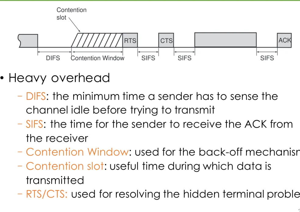
• Heavy overhead
⎻ DIFS: the minimum time a sender has to sense the channel idle before trying to transmit
⎻ SIFS: the time for the sender to receive the ACK from the receiver
⎻ Contention Window: used for the back-off mechanism
⎻ Contention slot: useful time during which data is transmitted
⎻ RTS/CTS: used for resolving the hidden terminal problem
3
smaller channels simultaneously according to their traffic demands, thereby amortizing MAC coordination and increasing overall effi- ciency. We call this method fine-grained channel access for high data rate WLANs.
It is, however, non-trivial to divide a wide channel band into mul- tiple subchannels without losing useful channel bandwidth. One common practice is to allocate both edges of two adjacent subchan- nels as a “guard band” so that the useful transmissions are properly spaced to avoid interfering with each other. These guard bands can add up to significant overhead, though, especially if the number of subchannels is large. For example, 802.11a uses a 1.875MHz guard band at both edges of every channel. If a 20MHz channel is divided into four 5MHz subchannels, the overhead will amount to 75% of the total bandwidth. Further, the guard band width cannot be easily reduced due to power mask requirements and the difficulty of filter designs, independent of the width of a subchannel.
Orthogonal frequency division multiplexing (OFDM) is a well- understood PHY-layer technology that can eliminate the need to have guard bands, if the frequency and width of subchannels are strategically picked and transmission on each subchannel is syn-
chronized in a way to become “orthogonal”, and hence non-interfering, to one another. Although some cellular networks (e.g., WiMAX [2]
and 3GPP LTE [3]) have proposed using OFDM in channel multi- access (OFDMA), doing so requires tight synchronization among user handsets and they cannot support random access. It thus re- mains a new technical challenge for how to use OFDM-type chan- nelization for fine-grained channel access among distributed and asynchronous stations in a random access WLAN, where it is im- practical and unnecessary to achieve similar tight synchronization.
In this paper, we present the design and implementation of FICA, a novel cross-layer architecture based on OFDM that enables fine- grained subchannel random access in a high data rate WLAN. FICA introduces two key techniques to address the aforementioned chal- lenges:
• FICA proposes a new PHY architecture based on OFDM.
Solely relying on the coordination mechanisms provided by existing WLANs, carrier-sensing and broadcasting, FICA re- tains orthogonality among subchannels with low overhead.
• FICA employs a novel frequency-domain contention method that uses physical layer RTS/CTS signaling and frequency- domain backoff for contending subchannels. We show that frequency-domain contention is much more efficient than the conventional time-domain contention mechanism in a fine- grained channel access environment.
We have implemented a FICA prototype on the Sora software ra- dio platform [24]. Our implementation demonstrates the feasibility of our key techniques for both PHY and MAC design. We further use detailed simulation to evaluate FICA in large-scale wireless en- vironments under different traffic patterns. Our results show that FICA has up to a 4-fold gain in efficiency compared to existing 802.11n with all its optimizations.
In summary, this paper makes the following contributions. (1) We describe and examine the efficiency issue of current MAC protocols in the context of high-speed WLANs, and argue that this issue can be resolved by fine-grained channel access. (2) We design and im- plement FICA, a protocol that enables fine-grained subchannel ran- dom access in WLANs; (3) We demonstrate the feasibility of FICA with a prototype implementation on a software radio platform, and evaluate its performance using detailed simulation. To the best of our knowledge, FICA is the first system that enables fine-grained channel access in WLANs.
Contention slot
DIFS SIFS
ACK
Contention Window
(a) Basic access
Contention slot
DIFS SIFS SIFS SIFS
RTS CTS ACK
Contention Window
(b) With RTS/CTS handshake
Figure 1: Illustration of CSMA/CA access method.
The rest of paper is organized as follows. Section 2 provides a detailed analysis of the source of inefficiency in current MAC pro- tocols. We then describe the design of FICA in Section 3 and eval- uate its performance using simulation in Section 4. After describ- ing the implementation of a FICA prototype using a software radio platform in Section 5, we evaluate its performance in Section 6.
Finally, Section 7 discusses related work and Section 8 concludes.
2. BACKGROUND AND CHALLENGES 2.1 Inefficiency of Current WLANs
State-of-the-art MAC protocols in wireless LANs manage the whole channel (e.g., 20/40MHz width) as a single resource. The MAC protocol arbitrates access among multiple potential senders and selects one as the winner, which then consumes the whole channel resource to transmit. If multiple senders transmit at the same time, collisions may happen and receivers will likely fail to decode the transmissions.
Current 802.11 WLANs use carrier sensing multiple access with collision avoidance (CSMA/CA) for their MAC protocol. When the channel is busy, all contending nodes wait until the channel be- comes free. The MAC employs a random backoff scheme to avoid having multiple nodes transmitting simultaneously. Each node will randomly choose a number b within a contention window [0, CW ), and wait for b time slots before it starts transmitting. If a node de- tects a transmission detected its backoff period, it will freeze the backoff counter until the channel is free again. If two nodes ran- domly choose the same backoff time, their transmissions will even- tually collide. A collision is usually detected by a missing acknowl- edgement (ACK) from the receiver. When a collision is detected, a sender will double its contention window CW according to the binary exponential backoff (BEB) algorithm to further reduce the collision probability for the next transmission.
Figure 1 illustrates the channel access timing diagram of the 802.11 MAC. Figure 1(a) is the basic access method, and Fig- ure 1(b) shows channel access with the optional RTS/CTS hand- shake to handle hidden terminals. The Short Inter-frame Space (SIFS) is the shortest time interval required for a receiver to re- turn a message to a sender. It is determined by Equation 1, where trf_delay is the delay incurred to transfer digital signals from the RF antenna to the processing unit, tproc is the time needed for the pro- cessing unit to operate on the incoming signals, and tTxRx is the time needed for the RF front-end to switch from receiving mode to trans- mitting. Normally, SIFS is about 10–16µs. The Distributed Inter- frame Space (DIFS) is determined based on SIFS and the backoff slot time, as shown in Equation 2. DIFS is defined to support prior- ities in CSMA/CA and should be larger than SIFS. The backoff slot time is critical. It is the minimal time needed for a node to sense the channel condition and acquire the channel. Slot time is deter- mined by Equation 3, where tcca is the time for a node to measure
Inefficiency of 802.11MAC
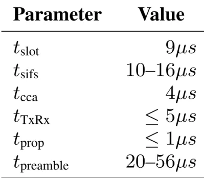
• tslot: sending time
• tsifs: SIFS time
• tcca: time to reliably sense a channel
• tTxRx: time needed to change
from rcv/snd mode & vice-versa
• tprop: signal propagation time
• tpreamble: time for sending training symbols (channel estimation)
4
Parameter Value
tslot 9µs
tsifs 10–16µs
tcca 4µs
tTxRx ≤ 5µs
tprop ≤ 1µs
tpreamble 20–56µs
Table 1: Timing parameters of 802.11.
0 10 20 30 40 50 60 70 80 90
0 200 400 600 800 1000
Efficiency(%)
PHY Data Rate (Mbps)
802.11b 802.11a/g
802.11n
802.11ac/ad
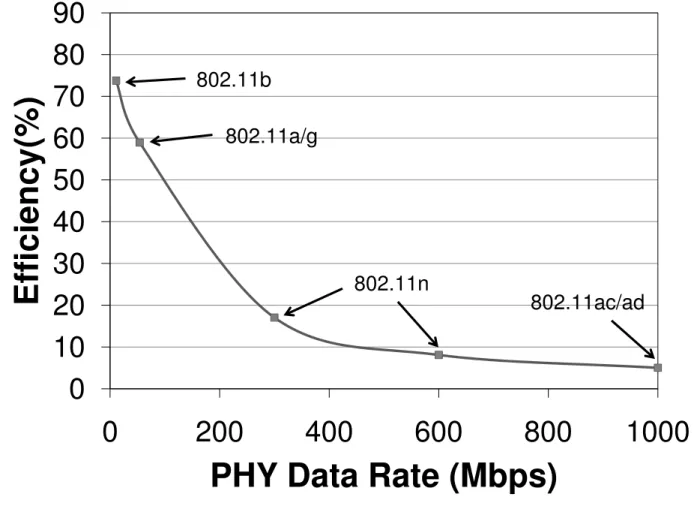
Figure 2: Inefficiency of 802.11 MAC at high data rates with a typical Ethernet MTU (1500B).
the channel energy to decide the channel status, and tprop is the time for the radio signal to reach the maximal distance of the network.
tsifs = trf_delay + tproc + tTxRx, (1) tdifs = tsifs + 2 · tslot, (2) tslot = tcca + tTxRx + tprop + tproc, (3) Using these values, we can build a simple analytical model to compute the efficiency ratio for CSMA/CA. Since a node chooses a random number uniformly from the contention window [0, CW ), the expected number of backoff slots is W = CW2 . Equation 4 gives the efficiency ratio for the basic access of CSMA/CA:
η = tdata
tslot · W + tdifs + tpreamble + tsifs + tack + tdata , (4) where tdata is the time used for data transmission, tpreamble is the time used to transmit per-frame training symbols and tack is the time used for the ACK frame.
Only tdata is used for transmitting application data, while all other times are overheads. Some overheads are constrained by physi- cal laws and current contraints in state-of-the-art radio electronics.
For example, you cannot reduce tprop less than 1µs to cover a net- work with a radius of a few hundreds of meters. It is also diffi- cult to reduce tTxRx since the RF circuit requires a few microsec- ond to settle down for sending or receiving. Others are needed for the correct operation of the protocol. For example, we need training symbols for reliable estimation of the wireless channel for each frame, thus tpreamble is essential. The average backoff slots, denoted by W , reflects the ability of CSMA/CA to avoid colli- sions. Thus, to work well in normal network settings, we need a reasonably large W . ACKs are also needed to detect collisions and other losses, thus in general we do not want to remove tack. Table 1 outlines some timing parameters defined in 802.11. They remain similar across the different standards of 802.11a/g/n except for the preamble; since 802.11n uses MIMO, it requires more train- ing symbols in its preamble.
Therefore, when the PHY data rate increases, only tdata will be reduced proportionally, while the other parameters remain largely unchanged. As a consequence, the efficiency ratio η decreases in-
Frequency
f1 f2 f3
Channel bandwidth
Guard band
(a) Normal frequency division multiplexing
Frequency f1 f2 f3
Channel bandwidth
Spectrum saved
(b) OFDM
Figure 3: OFDM achieves higher spectrum efficiency.
versely proportionally. Figure 2 illustrates such a phenomenon: the efficiency quickly decreases from 60% at 54Mbps (802.11a/g) to less than 10% at 1Gbps (future 802.11ac/ad).
As mentioned in Section 1, transmitting larger frames will im- prove the efficiency ratio, but such a frame-aggregation approach has practical limitations. Fine-grained channel access will be a better approach, if we can divide the whole channel into smaller sub-channels efficiently and allow different nodes to access dif- ferent sub-channels simultaneously. Enabling concurrent transmis- sion across sub-channels is in effect an aggregation and opportunity to amortize the MAC overhead across different nodes.
2.2 An OFDM Primer
Orthogonal Frequency Division Multiplexing (OFDM) has be- come increasingly popular in modern wireless communications [17].
It has been embraced by many existing wireless standards like IEEE 802.11a/g/n, WiMax [2], and by future standards like 3GPP LTE [3].
Cognitive radio technologies also mainly rely on OFDM to use non-contiguous spectrum bands for communication [19].
OFDM divides a spectrum band into many small and partially overlapping signal-carrying frequency bands called subcarriers. The subcarrier frequencies are chosen so that they are “orthogonal” to one another, meaning that cross-talk between subcarriers sums up to zero even though they are overlapping (Figure 3). OFDM can therefore pack subcarriers tightly together without inter-carrier in- terference, eliminating the need to have guard bands.
OFDM can be efficiently implemented using (inverse) Fast Fourier Transform (iFFT/FFT). In an OFDM system with FFT size N, each subcarrier has exactly the same width of NB and the subcar- rier central points are located at frequencies of fc + 2πnBN , n =
−N2 ..(N2 − 1), where fc is the central frequency of the channel and B is the channel width. Different modulations (e.g., BPSK, QPSK, etc.) can be applied to each subcarrier independently. After modulating information onto each subcarrier, the sender performs an iFFT to convert the frequency domain presentation to N time- domain samples which can be sent over the air. The time needed to transmit these N samples is usually called the FFT period, which is equal to NB seconds. Thus, given a fixed channel width, a larger N means a longer FFT period. Then, at the receiver side, the sig- nal can be converted back to the frequency domain using the FFT, where each subcarrier can be demodulated independently.
149
Inefficiency of 802.11MAC
• Only tdata is used for transmitting application data, the others times are overhead
• As PHY data rate increases, only tdata decreases
proportionally while the overhead remains the same
⎻ (100bits) need 17us for 6Mb/s, but only 1.85 us for 54Mb/s
5
Channel efficiency:
⌘ = tdata
tslotW + tDIFS + tPLCP + tSIFS + tACK + tdata overhead
Inefficiency of 802.11MAC
6
Parameter Value
tslot 9µs
tsifs 10–16µs
tcca 4µs
tTxRx ≤ 5µs
tprop ≤ 1µs
tpreamble 20–56µs
Table 1: Timing parameters of 802.11.
0 10 20 30 40 50 60 70 80 90
0 200 400 600 800 1000
Efficiency(%)
PHY Data Rate (Mbps)
802.11b 802.11a/g
802.11n
802.11ac/ad
Figure 2: Inefficiency of 802.11 MAC at high data rates with a typical Ethernet MTU (1500B).
the channel energy to decide the channel status, and tprop is the time for the radio signal to reach the maximal distance of the network.
tsifs = trf_delay + tproc + tTxRx, (1) tdifs = tsifs + 2 · tslot, (2) tslot = tcca + tTxRx + tprop + tproc, (3) Using these values, we can build a simple analytical model to compute the efficiency ratio for CSMA/CA. Since a node chooses a random number uniformly from the contention window [0, CW ), the expected number of backoff slots is W = CW2 . Equation 4 gives the efficiency ratio for the basic access of CSMA/CA:
η = tdata
tslot · W + tdifs + tpreamble + tsifs + tack + tdata , (4) where tdata is the time used for data transmission, tpreamble is the time used to transmit per-frame training symbols and tack is the time used for the ACK frame.
Only tdata is used for transmitting application data, while all other times are overheads. Some overheads are constrained by physi- cal laws and current contraints in state-of-the-art radio electronics.
For example, you cannot reduce tprop less than 1µs to cover a net- work with a radius of a few hundreds of meters. It is also diffi- cult to reduce tTxRx since the RF circuit requires a few microsec- ond to settle down for sending or receiving. Others are needed for the correct operation of the protocol. For example, we need training symbols for reliable estimation of the wireless channel for each frame, thus tpreamble is essential. The average backoff slots, denoted by W , reflects the ability of CSMA/CA to avoid colli- sions. Thus, to work well in normal network settings, we need a reasonably large W . ACKs are also needed to detect collisions and other losses, thus in general we do not want to remove tack. Table 1 outlines some timing parameters defined in 802.11. They remain similar across the different standards of 802.11a/g/n except for the preamble; since 802.11n uses MIMO, it requires more train- ing symbols in its preamble.
Therefore, when the PHY data rate increases, only tdata will be reduced proportionally, while the other parameters remain largely unchanged. As a consequence, the efficiency ratio η decreases in-
Frequency
f1 f2 f3
Channel bandwidth
Guard band
(a) Normal frequency division multiplexing
Frequency f1 f2 f3
Channel bandwidth
Spectrum saved
(b) OFDM
Figure 3: OFDM achieves higher spectrum efficiency.
versely proportionally. Figure 2 illustrates such a phenomenon: the efficiency quickly decreases from 60% at 54Mbps (802.11a/g) to less than 10% at 1Gbps (future 802.11ac/ad).
As mentioned in Section 1, transmitting larger frames will im- prove the efficiency ratio, but such a frame-aggregation approach has practical limitations. Fine-grained channel access will be a better approach, if we can divide the whole channel into smaller sub-channels efficiently and allow different nodes to access dif- ferent sub-channels simultaneously. Enabling concurrent transmis- sion across sub-channels is in effect an aggregation and opportunity to amortize the MAC overhead across different nodes.
2.2 An OFDM Primer
Orthogonal Frequency Division Multiplexing (OFDM) has be- come increasingly popular in modern wireless communications [17].
It has been embraced by many existing wireless standards like IEEE 802.11a/g/n, WiMax [2], and by future standards like 3GPP LTE [3].
Cognitive radio technologies also mainly rely on OFDM to use non-contiguous spectrum bands for communication [19].
OFDM divides a spectrum band into many small and partially overlapping signal-carrying frequency bands called subcarriers. The subcarrier frequencies are chosen so that they are “orthogonal” to one another, meaning that cross-talk between subcarriers sums up to zero even though they are overlapping (Figure 3). OFDM can therefore pack subcarriers tightly together without inter-carrier in- terference, eliminating the need to have guard bands.
OFDM can be efficiently implemented using (inverse) Fast Fourier Transform (iFFT/FFT). In an OFDM system with FFT size N, each subcarrier has exactly the same width of NB and the subcar- rier central points are located at frequencies of fc + 2πnBN , n =
−N2 ..(N2 − 1), where fc is the central frequency of the channel and B is the channel width. Different modulations (e.g., BPSK, QPSK, etc.) can be applied to each subcarrier independently. After modulating information onto each subcarrier, the sender performs an iFFT to convert the frequency domain presentation to N time- domain samples which can be sent over the air. The time needed to transmit these N samples is usually called the FFT period, which is equal to NB seconds. Thus, given a fixed channel width, a larger N means a longer FFT period. Then, at the receiver side, the sig- nal can be converted back to the frequency domain using the FFT, where each subcarrier can be demodulated independently.
149
Efficiency decreases as the PHY data rate increases
How to solve inefficiency
• Frame aggregation : Transmitting larger frames decreases the inefficiency
⎻ What about low latency applications?
• Divide the channel in multiple subchannels
⎻ Senders can transmit simultaneously
⎻ One sender can transmit on more channels than the others (similar to OFDMA)
⎻ J each STA has a lower PHY rate, but the aggregate rate is unchanged
⎻ J all the STAs only need one round of the contention procedure, as a result lowering the overhead on
average
7
OFDM
• Divide the available spectrum into many
partially overlapping narrowband subcarriers
• Choose subcarrier frequencies so that they are orthogonal to one another, thereby
cancelling cross-talk
• Thus, eliminating the need for guard bands
• Used in 802.11a/g/n, WiMax and other future standards
8
Fine-Grained Channel Access
• OFDMA does not support random access
• Design a system OFDM like that allows random access
⎻ Split channel width into multiple subcarriers
⎻ A number of subcarriers form a sub-channel
⎻ Each subcarrier can use a different modulation scheme
⎻ Assign each sender a number of sub-channels according to their sending demands
⎻ Apply OFDM on the whole channel to eliminate the need of guard bands
⎻ Revise the MAC contention mechanism used in 802.11
9
Basic Idea
10
FICA – Basic Idea for uplink using 20-MHz channel
transmission opportunity arises when whole channel is idle
all stations contend for different sub-channels (one or many) after channel idle for DIFS time
• Transmission opportunity arises when the whole channel becomes idle
• All STAs contend for different sub-channels after DIFS
• All STAs transmit M-RTS simultaneously on randomly- selected sub-channels
• AP picks a winner for each sub-channel and broadcast the result using M-CRS
• Selected STAs start sending
• ACK for the correctly delivered packets
Basic Idea
11
FICA – Basic Idea for uplink using 20-MHz channel
transmission opportunity arises when whole channel is idle
all stations contend for different sub-channels (one or many) after channel idle for DIFS time
all stations transmit M-RTS signal simultaneously on different subcarriers
• Transmission opportunity arises when the whole channel becomes idle
• All STAs contend for different sub-channels after DIFS
• All STAs transmit M-RTS simultaneously on randomly- selected sub-channels
• AP picks a winner for each sub-channel and broadcast the result using M-CRS
• Selected STAs start sending
• ACK for the correctly delivered packets
Frequency-Domain Contention
Basic Idea
12
FICA – Basic Idea for uplink using 20-MHz channel
transmission opportunity arises when whole channel is idle
all stations contend for different sub-channels (one or many) after channel idle for DIFS time
all stations transmit M-RTS signal simultaneously on different subcarriers
AP chooses a winner for each subchannel and broadcasts the result using M-CTS
• Transmission opportunity arises when the whole channel becomes idle
• All STAs contend for different sub-channels after DIFS
• All STAs transmit M-RTS simultaneously on randomly- selected sub-channels
• AP picks a winner for each sub-channel and broadcast the result using M-CRS
• Selected STAs start sending
• ACK for the correctly delivered packets
Basic Idea
13
FICA – Basic Idea for uplink using 20-MHz channel
transmission opportunity arises when whole channel is idle
all stations contend for different sub-channels (one or many) after channel idle for DIFS time
all stations transmit M-RTS signal simultaneously on different subcarriers
AP chooses a winner for each subchannel and broadcasts the result using M-CTS Elected stations start sending
• Transmission opportunity arises when the whole channel becomes idle
• All STAs contend for different sub-channels after DIFS
• All STAs transmit M-RTS simultaneously on randomly- selected sub-channels
• AP picks a winner for each sub-channel and broadcast the result using M-CRS
• Selected STAs start sending
• ACK for the correctly delivered packets
Basic Idea
14
FICA – Basic Idea for uplink using 20-MHz channel
transmission opportunity arises when whole channel is idle
all stations contend for different sub-channels (one or many) after channel idle for DIFS time
all stations transmit M-RTS signal simultaneously on different subcarriers
AP chooses a winner for each subchannel and broadcasts the result using M-CTS Elected stations start sending
ACK for the packets are sent
• Transmission opportunity arises when the whole channel becomes idle
• All STAs contend for different sub-channels after DIFS
• All STAs transmit M-RTS simultaneously on randomly- selected sub-channels
• AP picks a winner for each sub-channel and broadcast the result using M-CRS
• Selected STAs start sending
• ACK for the correctly delivered packets
Frequency-Domain Contention
• The entire channel is split into multiple subcarriers
• 16 data subcarriers + 1 pilot subcarrier form a sub- channel
• Each node contends for one or more channels by means of M-RTS/M-CTS
• M-RTS/M-CTS use simple binary amplitude modulation (BAM)
• Receivers can simply detect BAM symbol by
checking energy level (zero amplitude = 0 else 1 )
• K subcarriers from each sub-channel form a contention band
15
Frequency-Domain Contention
• Contending nodes randomly pick a subcarrier within the subchannel’s contention band and send a signal “1” using BAM
• The AP chooses a winner based on a
predefined rule (e.g. the one picking the smallest subcarrier index as the winner)
• The AP sends an M-CTS back on the same subcarrier
• The STA detects itself as the winner if the tone tagged in the returned M-CTS matching what it has selected
• Winners wait SIFS and then start transmitting
16
Benefits of Freq. Domain Contention
• No need to random backoff, further saving protocol overhead
• Single broadcast domain à naturally resolve the hidden terminal problem without using expensive traditional RTS/CTS
17
Practical Issues
• Collisions may still occur
⎻ When STAs pick the same subcarrier in M-R TS
• How many subcarriers should be use for contention purposes?
⎻ Related to the number of STAs with traffic demands simultaneously
• Hash(receiverID) between 0 and (m-1) to represent receiver information in M-RTS
⎻ The AP does not explicitly know who is the winner
• Time synchronization is critical
⎻ STA needs to synchronize with each other to avoid inter-subchannel interference
18
Frequency-Domain Backoff
• In a heavily-contended network, multiple senders could contend on the same
subcarrier à collisions
• Limit the number of channels a sender can contend for
⎻ Pick up to n subchannels to contend for
⎻ n = min(Cmax ,lqueue)
⎻ Cmax decreases when collisions are detected
⎻ Lqueue: the number of fragments in node’s sending queue
⎻ Mechanism similar to exponential backoff and additive increase/multiplicative decrease
19
Performance – Efficiency
• Verified via simulations
20
0 10 20 30 40 50 60 70 80 90
0 200 400 600
Efficiency (%)
PHY Data Rate (Mbps)
802.11 FICA AIMD FICA RMAX
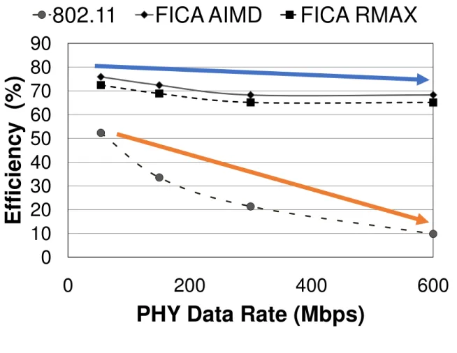
Figure 8: Efficiency ratio of 802.11 and FICA with different PHY data rates. No frame aggregation is enabled.
current 802.11a/g rates only provide around a 50% efficiency ra- tio, and this ratio decreases rapidly with the increase of the PHY data rate. However, by enabling fine-grained channel access, FICA can achieve a much higher efficiency ratio in the same situation.
This benefit is because different stations can access different sub- channels simultaneously. Thus the per-access MAC overhead is amortized among all concurrent nodes. Also, we find that FICA AIMD has slightly better performance than FICA RMAX. As we will see in subsequent experiments, FICA AIMD consistently per- forms better. We hypothesize that this is because FICA AIMD ad- justs Cmax much smoother compared to FICA RMAX. However, a deep analysis on the optimal frequency-domain backoff strategy remains future work.
This scenario is the worst case for 802.11n. We show this case to demonstrate how significant the MAC overhead can be at high PHY data rates, and that techniques like FICA or frame aggregation are indeed necessary for efficiency.
Full aggregation. Here, we show the best case of 802.11n with frame aggregation. In this experiment, all nodes are saturated so that the frame aggregation can work most efficiently. Figure 9 shows throughput efficiency with different numbers of contending nodes at two PHY data rates, 150Mbps and 600Mbps, respectively.
In both cases, the efficiency of 802.11n has been significantly im- proved due to frame aggregation. Since all nodes are saturated, the aggregation level is very high: 12 frames (or 18KB) on average.
FICA still has slightly better performance than 802.11n even in this case, though, because FICA has slightly fewer collisions com- pared to 802.11n. To understand why, consider the operation of frequency domain contention. When there are many stations con- tending for a subchannel, if two stations happen to pick up the same subcarrier to send their signals, it does not necessarily result in a collision. A collision occurs only when the collided subcarrier is also chosen as the winner as nodes contend for subchannels. In the next contention period, all stations will pick a different random number again. This situation is unlike time-domain backoff used in 802.11: when two stations pick the same backoff slots they will eventually collide with each other.
Mixed traffic. Finally we evaluate a situation in between the two extremes. We have five saturated stations that always have full- sized frames to transmit. In addition, there are a variable number of nodes that have small but delay-sensitive traffic representing, for instance, video conferencing or Web browsing. We choose the load of this delay sensitive traffic uniformly from 800Kbps to 5Mbps, and the packet size from 800–1300 bytes. Figure 10 shows the effi- ciency results of this scenario as a function of the number of delay- sensitive nodes. With a few delay-sensitive nodes, the through- put efficiency of the network is significantly reduced for 802.11n.
Since the delay sensitive flows cannot be aggregated, their access
0 10 20 30 40 50 60 70 80 90
0 10 20 30 40 50
Efficiency (%)
# of nodes
802.11
FICA RMAX
FICA AIMD
0 10 20 30 40 50 60 70 80 90
0 10 20 30 40 50
Efficiency (%)
# of nodes
802.11
FICA RMAX
FICA AIMD
(a) (b)
Figure 9: Full aggregation case. For 802.11, the maximal aggre- gated frame size is 28KB. All nodes are saturated. (a) 802.11 PHY 150Mbps; FICA 145Mbps. (b) 802.11 PHY 600Mbps;
FICA 580Mbps.
0 10 20 30 40 50 60 70 80 90
5 10 15 20 25 30 35 40 45
Efficiency (%)
# of delay sensitive nodes
802.11
FICA RMAX FICA AIMD
0 10 20 30 40 50 60 70 80 90
5 10 15 20 25 30 35 40 45
Efficeiency (%)
# of delay-sensitive nodes
802.11
FICA RMAX
FICA AIMD
(a) (b)
Figure 10: Mixed traffic. Five nodes are fully saturated. All other nodes have delay-sensitive traffic with a uniform distri- bution between 800Kbps to 5Mbps. (a) 802.11 PHY 150Mbps;
FICA 145Mbps. (b) 802.11 PHY 600Mbps; FICA 580Mbps.
to the channel is much less efficient. Thus, the overall channel uti- lization is reduced. However, with FICA such nodes can request access to fewer subchannels, leaving the other subchannels for use by other nodes. Consequently, the overall network efficiency re- mains at a high level, improving upon 802.11 from 16% up to 4 times better at the high PHY data rates.
5. IMPLEMENTATION
We have also implemented the basic mechanisms of FICA us- ing Sora, a fully programmable software radio platform based on commodity general-purpose PC architectures [24]. Our FICA im- plementation is based on SoftWiFi, a software implementation of the 802.11a/b/g PHY/MAC [24]. We make the following modifi- cations: (1) we change the FFT size from 64-point to 256-point for DATA/ACK symbols and 512-point for M-RTS/M-CTS sym- bols; (2) we employ convolutional coding in each subchannel and decode data in each subchannel individually using the Viterbi al- gorithm; (3) we remove the random time-domain backoff in the CSMA MAC, and implement the M-RTS/M-CTS handshake after the channel is sensed idle.
FICA uses a PHY frame structure and synchronization algorithm similar to 802.11. A preamble precedes data symbols. The first symbol is used for symbol time synchronization (i.e., finding the boundary of symbols). It employs a self-repeating pattern in the time domain so that the receiver can detect it using auto-correlation.
The second symbol is used for channel estimation. To support 4x MIMO, another training symbol is needed. The last symbol en- codes the Physical Layer Convergence Protocol (PLCP) header us- ing BPSK and 1/2 convolutional coding. The PLCP header contains the modulation mode used in the following DATA symbols for the receiver to set the proper demodulating parameters.
155 Efficiency is nearly stable when the PHY data rate increases
Conclusion
• Traditional 802.11 MAC is inefficient for high PHY data-rates
• FICA addresses this inefficiency by using fine- grained channel access
• Employ a novel frequency-domain contention mechanism that uses physical layer RTS/CTS
signaling
• Have shown via simulations that FICA outperformed 802.11n
• Resolve the synchronization issue
21