國立臺灣大學電機資訊學院電信工程學研究所 博士論文
Graduate Institute of Communication Engineering College of Electrical Engineering and Computer Science
National Taiwan University Doctoral Dissertation
LTE 通訊系統用戶端之可重構濾波器設計
Design of Reconfigurable Filters at UEs of LTE Communication Systems
蔡涵昀 Han-Yun Tsai
指導教授:吳瑞北 博士 Advisor: Ruey-Beei Wu, Ph.D.
中華民國 107 年 7 月
July 2018
致謝
時間總在不知不覺中過去,從懵懵懂懂的新生到現在完成這本論文,這些年最 要感謝的就是我的指導教授,吳瑞北教授,在研究上,教導我以嚴謹的態度與不 同面向的思考去處理問題;在專業上,不厭其煩的給予指正和建議;在待人處事 上,更是讓我學習到很多對應方式和做事方法。感謝口試委員,吳宗霖教授、郭 仁財教授、張志揚教授、林丁丙教授、陳永裕教授、洪子聖教授、黃立廷教授以 及郭維德博士,願意撥冗前來,並且給我許多寶貴的建議與指正。
再來要感謝的就是黃定彝學長,從一進入實驗室起,就給予我很多的幫助和指 導,在我研究卡關時,不厭其煩與我討論,指點我方向;在我撰寫報告、論文或 是製作投影片,給我很多建議和提醒。也很謝謝沈澤旻學長,在量測上的指導,
儘管已經離校,還是願意撥空回來帶我量測,讓我對於量測操作更為熟稔。再來 是謝謝吳凱斌學長,在很多實驗室的事務上是仰賴學長的協助才得以順利完成。
最後是詩雅,是同學也是學姊,在博士班的日子中,謝謝有你在,一起處理實驗 室的大小事務、一起修課,更多的是互相打氣和鼓勵。
這麼多年來,認識很多學弟妹,有些學弟妹已經畢業,卻還是在我需要協助時 大力幫忙,真的很謝謝他們。也謝謝現在實驗室的學弟妹們,瑋儒、余聰、貫宇、
皓崴、昱志、竪元、思綺以及裕盛,協助我處理不少實驗室的事情。
最後要感謝的就是我的家人,他們是我最有力的後盾和最堅固的避風港,感謝 爸媽給我的大力支持以及無怨無悔的包容,感謝家人們對我的理解和鼓勵。謝謝 您們作為我這麼多年心裡最大的支柱,讓我能堅持並完成博士學位。
在台大電信所的期間,要感謝的人真的很多,教授們、學長姐、學弟妹、同學 好友,還有許多位助理和所上的職員,很多事情上都給了我很大的幫忙,真的很 感謝。
最後,在此感謝所有協助我、支持我、鼓勵我以及陪伴我的人,謝謝您們!
蔡涵昀 謹誌 於 台大 2018 年 8 月
中文摘要
本論文主要研究可重構濾波器的設計,包含使用微帶線共振器以及聲波共振器。
第一部份為固定比例頻寬之可重構濾波器,利用可調之外部品質因子維持通帶內 反射損耗的響應,使用一具有接地傳輸線段負載之網式雙模共振器及兩組可調式 電容來實現,固定比例頻寬是利用具有接地傳輸線段負載之網式雙模濾波器的特 性來達成,一組可變電容做為調整濾波器之中心頻率,另一組則接於饋入傳輸線 段之ㄧ端,維持外部品質因子以調整通帶內的反射損耗。基於此設計概念,論文 中所提之固定比例頻寬可重構濾波器,在可調頻率範圍中,可以使反射損耗皆維 持在 20dB,且插入損耗小於 2.9dB,可改善一般可重構濾波器,反射損耗與插入 損耗會隨著中心頻率下降而變差的情況。
第二部分為使用薄膜聲波共振器設計可重構濾波器,分別使用一般高機電耦合 係數之薄膜聲波共振器與可調式薄膜聲波共振器。本論文中所提之薄膜聲波濾波 器皆使用微波濾波器的耦合理論進行設計,將薄膜聲波共振器串聯一電感之電路 簡化為並聯 RLC 電路模型且作為濾波器的共振器,中心頻率、耦合係數以及外部 品質因子的調整,皆使用可調式電容進行設計。為了增加可重構濾波器的可調範 圍,使用具有高機電耦合係數之薄膜聲波共振器以及具有高品質因子之可調式電 容。基於此設計概念,此可重構濾波器使用機電耦合係數為 26% 的薄膜聲波共振 器以及品質因子為 150 的可調式電容,在插入損耗小於 4dB 的情況下可以達到 8.2%
的可調範圍。
由於外加之可變電容,會使可重構濾波器的頻率降低時,插入損耗隨之增加,
使用可調式薄膜共振器可有效改善此情況,可調式薄膜聲波共振器本身的可調機 制即可用來調整可重構濾波器的中心頻率,不須再額外加入可調式電容,故可重 構濾波器之可調範圍便由可調式薄膜共振器決定,在與使用高機電耦合係數薄膜 共振器設計之可重構濾波器相同規格下,使用可調式薄膜共振器設計之可重構濾 波器的可調範圍為 10%,而插入損耗則小於 2.24dB。
關鍵字 : 可重構濾波器、可調式濾波器、雙模共振器、網式共振器、可調式 外部品質因子、可變電容、聲波共振器、薄膜聲波共振器、可調式薄膜聲波共振 器、高機電耦合係數、高品質因子之可調式電容
ABSTRACT
This dissertation focuses on the research of reconfigurable filters using microstrip resonators and acoustic wave resonators. The first part is the constant fractional bandwidth (CFBW) reconfigurable filter with frequency invariant passband characteristics using tunable external quality factors. A grounded-stub loaded net-type dual-mode resonator and two sets of varactors for tuning both the center frequency and the return loss level are used to design the reconfigurable filter. The design is featured with the net-type dual-mode filter of a short grounded-stub so that the CFBW property can be assured. In addition to conventional design, a pair of varactors is added at the ends of feeding transmission lines to keep the external quality factors constant while tuning. From the design concept, the return losses of reconfigurable CFBW filter with tunable external quality factor maintain at 20dB and the insertion losses are below 2.9dB over the entire frequency tuning range. The design can improve the return loss and insertion loss of reconfigurable filters when the center frequency decreases.
The second part is the reconfigurable filters using film bulk acoustic resonators (FBARs), including high electromechanical coupling coefficient (kt
2) FBARs and tunable FBARs. The FBAR resonator and a series inductor are first represented by a simplified parallel RLC circuit model. The reconfigurable FBAR filters are then designed by applying the general coupled resonator filter theory, with tunable capacitors to adjust center frequencies, coupling coefficients and external quality factors. To increase the tuning ranges of reconfigurable filters, high kt2 FBARs and variable capacitors with high quality factor are used. In the presented reconfigurable filters using high kt2 FBARs, the tuning range is about 8.2% with < 4dB insertion loss by using high-Q digital capacitors of Q = 150. For deceasing the losses of extra tunable capacitors for tuning the center frequency, tunable FBARs are used to design the
reconfigurable filters. By the mechanism of tunable FBARs, the center frequency of reconfigurable filters is tuning by TFBARs, not extra tunable capacitors. The tuning range of reconfigurable filters is determined by tunable FBARs. In same specification, the tuning range of reconfigurable filters using tunable FBARs is about 10% and the insertion loss is below 2.24dB.
Index Terms – Reconfigurable filter, tunable filter, dual mode resonator, net-type resonator, tunable external quality factor, varactor, acoustic wave resonator, film bulk acoustic resonator (FBAR), tunable film bulk acoustic resonator (TFBAR), high electromechanical coupling coefficient, high-Q digital capacitors
CONTENTS
中文摘要 ... III
ABSTRACT ... V
LIST OF FIGURES ... X
LIST OF TABLES ...XIV
CHAPTER 1 ... 1
INTRODUCTION ... 1
1.1. MOTIVATION ... 1
1.2. LITERATURE SURVEY ... 4
1.3. CONTRIBUTIONS ... 11
1.4. ORGANIZATION OF THE DISSERTATION ... 12
CHAPTER 2 ... 13
BASIC THEORIES OF FILTERS AND ACOUSTIC RESONATORS ... 13
2.1. CHEBYSHEV FUNCTION FILTERS [65] ... 13
2.1.1. Lowpass Prototype Filters ... 14
2.1.2. Dissipation Effects on Bandpass Filters ... 16
2.2. COUPLED RESONATOR CIRCUITS [66] ... 16
2.2.1. General Coupling Matrix ... 17
2.2.2. Coupling Coefficient M ... 18
2.2.3. External Quality Factor Qe ... 22
2.3. BASIC THEORY OF ACOUSTIC WAVE RESONATOR [18][68][69] ... 24
2.3.1. Constitutive Equations of Piezoelectric material ... 26
2.3.2. Mechanical Wave Equation on Acoustic Wave Resonators ... 28
2.3.3. Equivalent Circuit Model of FBARs ... 34
2.3.4. FBARs with Lumped Components [73] ... 37
CHAPTER 3 ... 39
RECONFIGURABLE FILTERS USING NET-TYPE DUAL-MODE MICROSTRIP LINE ... 39
3.1. NET-TYPE DUAL-MODE RESONATORS ... 39
3.2. NET-TYPE DUAL-MODE RECONFIGURABLE FILTER ... 41
3.2.1. Design Specifications ... 42
3.2.2. Constant Coupling Coefficients ... 43
3.2.3. Tunable External Quality Factors ... 45
3.2.4. Net-type Dual-mode Reconfigurable Filters ... 47
3.3. EXPERIMENTAL VALIDATIONS ... 53
3.3.1. Net-type Dual-mode Recofigurable Filters Without Tunable External Quality Factors ... 53
3.3.2. Net-type Dual-mode Reocfigurable Filters With Tunable External Quality Factors ... 55
CHAPTER 4 ... 59
RECONFIGURABLE FILTERS USING FILM BULK ACOUSTIC RESONATORS ... 59
4.1. BASIC THEORIES OF FBARS ... 59
4.1.1. Derivation to Input Impedance of Layered FBARs ... 60
4.1.2. MBVD Model and Simplified Parallel RLC Model ... 64
4.2. DESIGN OF FBARS ... 66
4.2.1. Material of Piezoelectric Layers ... 66
4.2.2. Structure of FBARs ... 67
4.2.3. Comparison of Theoretical and Simulation Result ... 67
4.3. DESIGN OF RECONFIGURATION FILTERS USING FBARS ... 70
4.3.1. Design Specifications ... 70
4.3.2. Tunable Coupling Coefficient and External Quality Factor ... 71
4.3.3. Highest Band of Reconfigurable FABR Filters ... 73
4.3.4. Reconfigurable Filters Using FBARs ... 74
4.4. APPLICATION FOR LTEBANDS ... 81
4.5. EXPERIMENTAL VALIDATIONS USING COMMERCIAL SAWRESONATORS ... 82
CHAPTER 5 ... 87
RECONFIGURABLE FILTERS USING TUNABLE FILM BULK ACOUSTIC RESONATORS . 87 5.1. BASIC THEORIES OF TUNABLE FBARS ... 87
5.2. DESIGN OF TUNABLE FBARS ... 90
5.2.1. Material of Piezoelectric Layers ... 91
5.2.2. Structure of Tunable FBARs ... 92
5.2.3. Comparison of Theoretical and Simulation Result ... 94
5.3. DESIGN OF RECONFIGURABLE FILTERS USING TFBARS ... 96
5.4. APPLICATION FOR LTEBANDS ... 104
CHAPTER 6 ... 105
CONCLUSIONS ... 105
6.1. SUMMARY AND DISCUSSION ... 105
6.2. SUGGESTIONS FOR FUTURE RESEARCH ... 109
APPENDIX ... 112
REFERENCES ... 121
PUBLICATION LIST ... 131
LIST OF FIGURES
Fig. 1.1 An example illustration of current RF front-end architecture for 4G smartphone. [1] ... 2
Fig. 1.2 Application space for SAW/BAW filters or duplexers. [4]... 3
Fig. 2.1 The Chebyshev lowpass response. ... 14
Fig. 2.2 The n-pole lowpass prototype ladder network structures. ... 15
Fig. 2.3 The coupled-resonator circuit with electric coupling ... 19
Fig. 2.4 The coupled-resonator circuit with magnetic coupling ... 19
Fig. 2.5 The equivalent circuit model for mixed coupling of resonators ... 21
Fig. 2.6 The equivalent circuit model of I/O resonator with single loading. ... 21
Fig. 2.7 Phase response of S11. ... 23
Fig. 2.8 Structure of SAW/BAW resonators, (a) SAW resonator (b) BAW resonator. [67] ... 25
Fig. 2.9 Structure of FABR and SMR resonators, (a) FBAR resonator (b) SMR resonator. [17] ... 25
Fig. 2.10 The constitutive relation between electrical and mechanical variables. [69][70] ... 27
Fig. 2.11 An isotropic volume with orientation traction forces. ... 28
Fig. 2.12 The equivalent circuit model in non-piezoelectric material ... 35
Fig. 2.13 The mason equivalent circuit model for piezoelectric material ... 36
Fig. 2.14 Equivalent circuit model for the electrical behavior of piezoelectric material (a) Butterworth-Van Dyke model (b) modified Butterworth-Van Dyke model ... 36
Fig. 2.15 The input impedance response of a single FBAR ... 38
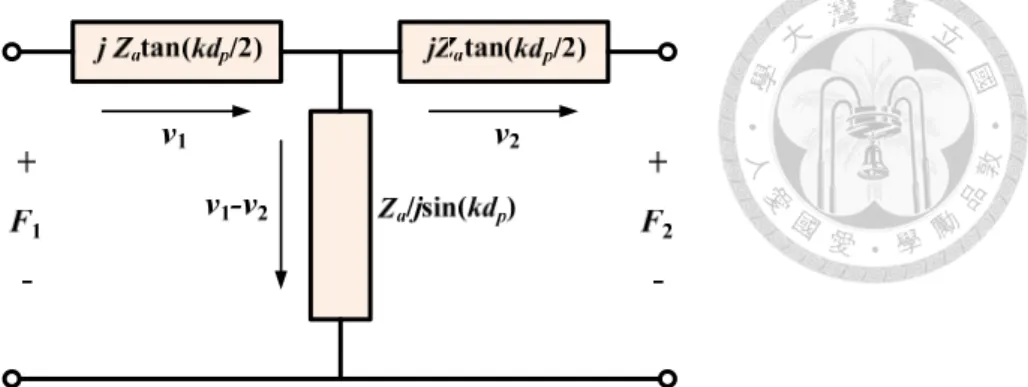
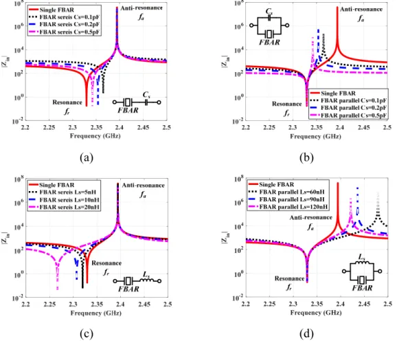
Fig. 2.16 The input impedance response of a single FBAR with lumped components, (a) series capacitors, (b) parallel capacitors, (c) series inductors, and (d) parallel inductors ... 38
Fig. 3.1 Equivalent circuit of a net-type dual-mode resonator with one short-ended and two open-ended transmission line sections. ... 40
Fig. 3.2 Net-type dual-mode resonator decomposed into (a) odd-mode and (b) even-mode equivalent circuits ... 40
Fig. 3.3 Circuit schematic of the net-type dual-mode reconfigurable filter. ... 41
Fig. 3.4 Net-type dual-mode tunable resonator decomposed into (a) odd-mode and (b) even-mode equivalent circuits ... 41
Fig. 3.5 Coupling coefficient versus frequency with Lb fixed at 14.15mm. ... 45
Fig. 3.6 Circuit schematic of the dual-mode reconfigurable CFBW filter with tunable external quality factors. ... 46
Fig. 3.7 Equivalent circuit model of tunable quality factors structure, (a) with varactors Ctq (b) equivalent transmission line. ... 46
Fig. 3.8 Structure of the proposed net-type dual-mode reconfigurable filter without tunable external quality factor. ... 48
Fig. 3.9 Simulation result of the reconfigurable filter without tunable external quality factors, (a) insertion loss and (b) return loss. ... 48
Fig. 3.10 Structure of the proposed net-type dual-mode CFBW reconfigurable filter with tunable external
quality factor. ... 50
Fig. 3.11 External quality factor versus frequency. ... 50
Fig. 3.12 Varactor capacitance Ct and Ctq versus frequency ... 51
Fig. 3.13 Simulation result of the dual-mode CFBW reconfigurable filter with tunable external quality factors, (a) insertion loss and (b) return loss. ... 51
Fig. 3.14 The insertion loss with loss of varactors (Ct and Ctq) ... 52
Fig. 3.15 The equivalent circuit of varactors. [76] ... 52
Fig. 3.16 Circuit photos of the typical net-type dual-mode reconfigurable filters ... 54
Fig. 3.17 Bias voltage versus center frequency of typical net-type dual-mode reconfigurable filters ... 54
Fig. 3.18 Measurement and simulation results of reconfigurable filter without tunable external quality factors, (a) insertion loss and (b) return loss. ... 55
Fig. 3.19 Circuit photos of CFBW reconfigurable filter. ... 56
Fig. 3.20 Bias voltage versus center frequency of CFBW reconfigurable filter. ... 57
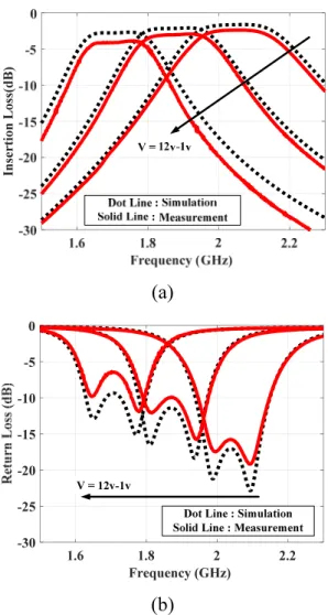
Fig. 3.21 Measurement and simulation results of net-type dual-mode CFBW reconfigurable filter with tunable external quality factors, (a) insertion loss and (b) return loss. ... 57
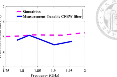
Fig. 3.22 The fractional bandwidth of simulation and measurement result ... 58
Fig. 4.1 Structure of a single FBAR resonator. (a) 3-D view of complete structure. (b) Cross section of basic structure. ... 60
Fig. 4.2 MBVD model of a single FBAR resonator. (a) Symbol of FBAR resonator. (b) MBVD equivalent circuit model of FBAR. ... 65
Fig. 4.3 Parallel RLC model of FBAR resonator in series with Ls. (a) Symbol of FBAR resonator in series with Ls. (b) Parallel RLC model. ... 65
Fig. 4.4 Relationship between thickness of piezoelectric layer (dp), thickness of electrodes (dt) and kt,eff 2. (a) The resonance and anti-resonance frequencies versus dp. (b) The kt,eff 2 versus thickness ratio (dt /dp). ... 68
Fig. 4.5 Simulated input impedance by CoventorWare, MBVD model, parallel RLC model and Zin from (4.21). ... 69
Fig. 4.6 General coupling structure of an N-order Chebyshev bandpass filter. ... 71
Fig. 4.7 Circuits of tunable coupling coefficient and external quality factor with parallel RLC model. (a) Coupling coefficient. (b) External quality factor. ... 72
Fig. 4.8 Circuit of the highest band of reconfigurable FBAR filters with parallel RLC model. The circuit parameters are CT1 = 0 pF, CT2 = 0.26 pF, Cm1 = 1.2 pF,Cm2 = 0.97 pF, Cq =2.7 pF, Cg1 =1.7 pF, Lg1 =3 nH. ... 73
Fig. 4.9 Filter response of the highest band of reconfigurable FBAR filter with simplified parallel RLC model and MBVD model. ... 74
Fig. 4.10 Desired coupling coefficients, M12 and M23, by theory and simulation versus frequency. ... 75
Fig. 4.12 Proposed circuit of reconfigurable FBAR filters using coupling capacitors. ... 75
Fig. 4.13 Responses of reconfigurable FBAR filters with MBVD equivalent circuit with Q=150 tunable capacitors. ... 76
Fig. 4.14 The lowest frequency band response of reconfigurable filters by considering loss of tunable capacitors CT, Cm and Cq. ... 76
Fig. 4.15 Circuit parameters of reconfigurable FBAR filters versus frequency. (a) CT for tuning center frequency (b) Cm for tuning coupling coefficient, and (c) Cq for tuning external quality factor. ... 78
Fig. 4.16 The simulation result with difference losses of Ls (RLs) (a) for the highest band and (b) for the lowest band. ... 79
Fig. 4.17 Responses of reconfigurable FBAR filters with MBVD equivalent circuit and Q=150 tunable capacitors, but without series Ls. ... 80
Fig. 4.18 Applications of reconfigurable FBAR filters on LTE bands. ... 80
Fig. 4.19 The layout of single SAW resonator experiment ... 82
Fig. 4.20 The simulation results and the measurement results of single SAW resonator ... 83
Fig. 4.21 The input impedance response of MBVD model and simplified parallel RLC model. ... 84
Fig. 4.22 The design circuit of SAW filter with simplified parallel RLC model and MBVD model, (a) Simplified parallel RLC model. (b) MBVD model ... 84
Fig. 4.23 The simulation result of SAW filter with simplified parallel RLC model and MBVD model .... 85
Fig. 4.24 The layout of real experiment of SAW filter. ... 85
Fig. 4.25 The circuit photos of single SAW resonator and SAW filter. (a) Single SAW resonator. (b) SAW filter. ... 86
Fig. 4.26 The measurement and simulation results of SAW filter ... 86
Fig. 5.1 Structure of a single TFBAR resonator. (a) 3-D view of complete structure. (b) Cross section of basic structure. ... 88
Fig. 5.2 Relationship between thickness of piezoelectric layer (HT =dp+dN), thickness of electrodes (dt) and kt,eff 2 at dN = 0 µm. (a) The resonance and anti-resonance frequencies versus dt and HT. (b) The kt,eff 2 versus dt and HT. ... 93
Fig. 5.3 The resonance and anti-resonance frequencies versus thickness of piezoelectric layer with doping (dN). ... 94
Fig. 5.4 Simulated input impedance by CoventorWare, MBVD model, simplified parallel RLC model, and calculated Zin. (a) dN = 0.1 µm. (b) dN = 0.4 µm . ... 95
Fig. 5.5 Circuit of the highest band of TFBAR filters with parallel RLC model. The circuit parameters are Leq1=2.808nH, Ceq1=1.93pF, Leq2=2.814nH, Ceq2=1.94pF, Cm1=35fF, Cm2=28fF, Cq=70fF, Cg1=0.33pF, Lg1=16.5nH. ... 97
Fig. 5.6 Filter responses of the highest band of TFBAR filters with simplified parallel RLC model and MBVD model. ... 98
Fig. 5.7 Desired coupling coefficients, M12 and M23, of theory and simulation versus frequency. ... 98
Fig. 5.8 External quality factor of theory and simulation versus frequency. ... 99
Fig. 5.9 Proposed circuit of reconfigurable filters using TFBARs and variable coupling capacitors. ... 99 Fig. 5.10 Filter responses of reconfigurable filters using TFBARs with MBVD equivalent circuit. ... 100 Fig. 5.11 Circuit parameters of reconfigurable filters using TFBARs versus frequency. (a) Cm for tuning
coupling coefficient and (b) Cq for tuning external quality factor. ... 101 Fig. 5.12. The simulation result with difference losses of Ls (RLs) (a) for the highest band and (b) for the
lowest band. ... 102 Fig. 5.13. Filter responses of reconfigurable filters using TFBARs with MBVD equivalent circuit without series Ls. ... 103 Fig. 5.14 Response of reconfigurable filters using TFBARs for LTE bands application. ... 103
LIST OF TABLES
Table 2.1 Brief summary of the mechanical wave equations and the electromagnetic equations [68] ... 33 Table 3.1 Design parameter of the net-type dual-mode reconfigurable filter without tunable external
quality factors (Unit: mm) ... 54 Table 3.2 Design parameter of the net-type dual-mode CFBW reconfigurable filter with tunable external
quality factors (Unit: mm) ... 56 Table 4.1 Circuit parameters of MBVD model and simplified parallel RLC model of single FBAR
resonator ... 69 Table 4.2 Circuit parameters of reconfigurable FBAR filter using coupling capacitors with MBVD model
... 77 Table 4.3 Circuit parameters of reconfigurable FBAR filters using coupling capacitors with MBVD model
for LTE bands ... 81 Table 4.4 Circuit parameters of MBVD model of datasheet and after fine-tuning ... 83 Table 4.5 Circuit parameters of MBVD model and simplified parallel RLC model of single SAW
resonator ... 83 Table 4.6 Circuit parameters of ideal circuit and real layout experiment of SAW filter ... 86 Table 5.1 Circuit parameters of MBVD equivalent circuit model and simplified parallel RLC equivalent
circuit model of single TFBAR resonator ... 96 Table 5.2 Circuit parameters of reconfigurable filters using TFBARs with MBVD equivalent circuit
model ... 101 Table 5.3 Circuit parameters of reconfigurable filters using TFBARs with MBVD model for LTE bands
... 103 Table 6.1 Comparison of literatures on microstrip reconfigurable filters ... 106 Table 6.2 Comparison of literatures on SAW/FBAR reconfigurable filters ... 111
Chapter 1 Introduction
1.1. Motivation
With the development of mobile communication systems, the requirement of massive data throughput and high-speed data rate has become more demanding. For achieving the higher data rate and wider bandwidth in the future, the required frequency bands have been increased. Filters are essential components in RF front-end of UE (User Equipment) part. Each frequency band needs at least one filter so the number of filters will increase enormously in multiband communication systems.
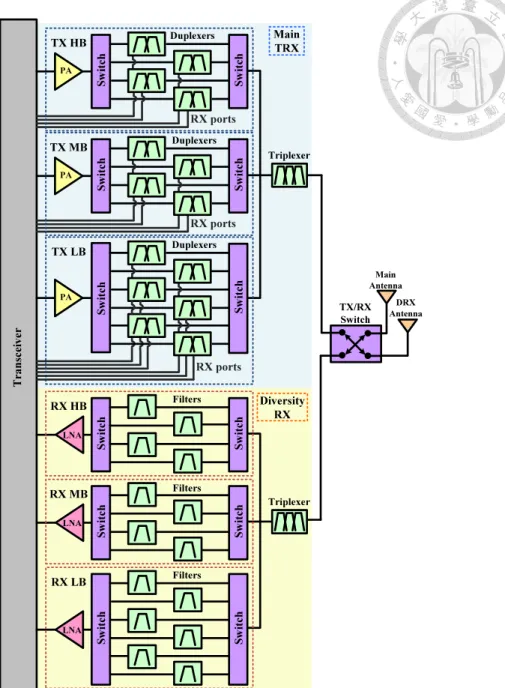
Figure 1.1 shows an example illustration of current RF front-end architecture for a 4G smartphone [1]. There are two parts of the RF front-end module, including main transceiver part and diversity receiver part. The duplexers are used in transceiver part and the filters are used in receiver part. Consider the next generation communication system, the RF front-end modules have to cover more and more frequency bands so that they will become more and more complex. To reduce the area of filters and design complexity of RF front-end modules, reconfigurable filters are attractive for simplifying the circuit.
Fig. 1.1 An example illustration of current RF front-end architecture for 4G smartphone. [1]
For 4G TLE communication systems, the higher isolation of adjacent frequency bands and lower insertion loss will become critical issues in reconfigurable filters.
Currently, the surface acoustic wave (SAW) filters are widely used because of their advantages of small size, low insertion loss, and high selectivity. The operating frequency of SAW resonators is decided by the pitch of interdigital transducer (IDT) electrodes which is limited by the manufacture [2], [3]. For higher frequencies, the bulk
Transceiver
Main TRX
Diversity RX
Main Antenna
DRX Antenna Triplexer
Triplexer
TX/RX Switch
RX HB
Switch Switch
Filters
LNA
RX MB
Switch Switch
Filters
LNA
RX LB
Switch Switch
Filters
LNA TX HB
PA
Switch Switch
RX ports Duplexers
TX MB
PA
Switch Switch
RX ports Duplexers
TX LB
PA
Switch Switch
RX ports Duplexers
Fig. 1.2 Application space for SAW/BAW filters or duplexers. [4]
acoustic wave (BAW) filters based on film bulk acoustic resonator (FBAR) or solidly mounted resonator (SMR) technologies will become the trend of next communication systems [4].
In this dissertation, the FBAR has been chosen to be main technology for design.
Figure 1.2 shows the application space for SAW/BAW filters or duplexers [4]. With the frequency, the SAW filters or duplexers are suitable for frequencies below 1.5GHz.
Above 1.5GHz, the performances of BAW filters or duplexers are better than SAW filters or duplexers. For higher frequencies, say 4.0GHz or above, the passive lumped elements circuit, dielectric material and LTCC (Low Temperature Co-fired Ceramic) are usually used, but their performances are not better than BAW filters or duplexers.
In order to obtain good filter performance, reconfigurable filters using SAW/FBAR resonators will be one solution to RF front-end modules. Based on the high quality factors of FBAR resonators above 2GHz, FBAR reconfigurable filter can be designed using tunable components and coupled resonator theory of filter design for LTE bands or next generation communication systems.
3 GHz 4 GHz
Frequency TC-SAW
BAW
Passive LC, Dielectric, LTCC, ...
Band 8 Band 3
Band 2 Band 7
WiMAX 3.5GHz WiMAX
2.5GHz Band 1
WLAN 2.4GHz
1 GHz 2 GHz
Conventional SAW
RX High Bands Band 5
GPS
Bluetooth Band 9
Band 4
RX Low Bands
Band 6
Frequency
1.2. Literature Survey
In 2017, the first release of 5G specifications, Release-15, has been issued by 3GPP [5]. For next generation communication systems, the required data rates are at least 20 Gb/s downlink and 10Gb/s uplink [6]. For achieving the specification, number of frequency bands will increase for wider bandwidth requirement. With increasing number of bands, there will be more filters. The area of filters on RF front-end will increases and the RF front-end design will be more and more complex. For reducing system complexity and area of filter on RF front-end module, the concept of reconfigurable filter has emerged.
Before introducing reconfigurable filters, a brief introduction for filters has been given. In wireless communication systems, the filter is one of important passive components. The specifications of filter will be different due to the system requirements.
For example, a highly compact lumped-element bandpass filter has been presented for L-band receiver by using LTCC to achieve system-on-package [7]. A bandpass filter has been designed at 3 to 5 GHz for ultra-wideband system by using PCB embedding passive technology [8]. When the operating frequency increases to millimeter-wave, waveguide filters have been considered to use, including gap waveguide filter [9] and substrate integrated waveguide (SIW) filter [10]. For V-band high data rate radios, a quasi-elliptic bandpass filter has been presented [11].
For smart mobile phone systems, the size of filters is a crucial issue. Several types of filters design such as the SIR filter [12], [13], the net-type multimode filter [14], [15]
and the folded SIW filter [16] have been proposed to reduce the circuit size. However, with the evolution of systems, the filter performances, such as selectivity and loss, present more challenging issue for filter design. The quality factor of general microstrip
resonators are not good enough. Currently, the acoustic wave filters are popularly used on smart mobile phones.
The acoustic wave filters include two different technologies, which can be distinguished by direction of acoustic wave propagation. One is surface acoustic wave (SAW), the other is bulk acoustic wave (BAW). The film bulk acoustic resonator (FBAR) and solidly mounted resonator (SMR) technologies are parts of BAW [3]. The SAW/BAW components do not need DC bias and AC is used to change the deformation of piezoelectric layer. In conventional SAW/FBAR filter design, the ladder-type and lattice-type are commonly used. The transmission zeros are designed by the resonance and anti-resonance frequency of SAW/FBAR resonators and then shunt and series SAW/FBAR resonators are used to form the desired filter response [4], [18]. In [19], the thin film bulk acoustic wave (FBAR) filters have been presented for high performance and miniaturization at 5GHz. In [20], the BAW-SMR filters have been designed by combining ladder and lattice type topology for high isolation and selectivity.
The BAW filters can be used to design duplexer with matching networks. Although the processes of SAW/BAW components, IC chips or lumped passive components are different, there are some packaging techniques to integrate those components. In [21], two BAW filter chips are designed by ladder type topology and they are flip-chip mounted onto the LTCC substrate. In [22], a technique for integrating active circuitry into the lid of the wafer-scale hermetic FBAR package is presented. The literature [23]
presents the integration of a SAW filter stacked on top of a BiCMOS transceiver chip in a plastic quad flat-pack no-lead (QFN) package.
In recent years, the requirement of reconfigurable filters have emerged in 4G LTE systems [24]-[27]. In traditional multi-band multi-mode RF front-ends [26], one of the main components is the duplexer. Because each transceiving band needs one duplexer,
more than one duplexer are used in the multi-band system. For receiving part of the RF front-end module, the filters are the main components. If some filters can be merged into one reconfigurable filter, the area and complexity can be reduced drastically. The reconfigurable filter and tunable filter are generally used. Strictly speaking, the filter characteristic in this dissertation tend to tunable filter.
As is implied by the name, the reconfigurable filters are composed of filters and tunable components. The tunable components or switches are usually based on solid-state, micro-electro-mechanical (MEMS) and ferroelectric materials, such as barium strontium titanate (BST). Two types of active components in reconfigurable filters, i.e., varactor diodes [28]-[36] and RF MEMS capacitors, [37]-[40], are usually used. The RF MEMS capacitors and varactor diodes have their own advantages. In terms of quality factor and insertion loss, RF MEMS capacitors have better performance than varactor diodes. However, because of the high tuning speed, low fabrication cost, and easy integration in circuits, varactor diodes are often used [41]. The quality factor of tunable components is one of key factors for the insertion loss of reconfigurable SAW/FBAR filters. The high-Q tunable capacitors have been shown in the literature [42]-[45], including MEMS varactors [42], BST varactors [43] and RF-MEMS digital capacitors [44], [45]. The RF-MEMS digital capacitors are composed of many MEMS switched capacitors in parallel to achieve high tuning range and high capacitance density. In [44], the COMS-MEMS 3-bits digital capacitors fabricated in 0.35μm BiCOMS process are presented. The quality factors are about 150 at 2GHz for capacitance from 21.5 fF to 1.36 pF. The quality factors of MEMS digital capacitors remains constant versus capacitance. The high-Q tunable capacitors can be realized by MEMS digital capacitors and the quality factors do not change dramatically with capacitance.
In designing a reconfigurable filter, one of the critical issues is to adjust the center frequency but keep certain filter response unchanged. Two types of bandwidth are often mentioned: constant fractional bandwidth (CFBW) and constant absolute bandwidth (CABW) responses [28], [29]. For CFBW reconfigurable filters, the coupling coefficients and external quality factors are required to maintain constant over the entire tuning range. For CABW reconfigurable filters, the coupling coefficients become lower while the external quality factors become higher with increased center frequency. For achieving the CFBW and CABW response, several methods have been presented. In [28], either CFBW or CABW reconfigurable filters can be achieved with different lumped capacitance by tuning electric coupling coefficients, which needs additional area. In addition, the reflection coefficient |S11| becomes worse when the center frequency of filter is tuned lower. At the lowest band of the reconfigurable filter, it is even larger than -10 dB and hence the band will not be suitable.
Reconfigurable filters with other special features are also proposed, including a reconfigurable bandstop filter with constant bandwidth [30], a planar reconfigurable filter with adjustable center frequency and fixed out-of-band rejection response [31], a dual-band reconfigurable filter with independently controllable passbands of two frequency bands [32], etc.
For achieving the constant coupling coefficient, the dual-mode reconfigurable filters have been presented. The concept of dual-mode filter has been used in designing reconfigurable filters previously [32], [33], [46]. However, the external quality factors are not designed appropriately to meet the requirement value when changing the center frequency of the reconfigurable filters. Although the filter responses still exist, the return losses degrade over the center frequency tuning range because the external quality factor is not the desired value. In [34], tunable structures for coupling
coefficients and external quality factors have been designed to achieve wideband reconfigurable filters. The constant 3dB-bandwidth of the reconfigurable filter with CABW response is 300MHz and the tunable fractional bandwidth of 12-95% can be achieved.
For most of the microstrip reconfigurable filters in the literatures [33], [47], [48], the insertion losses are difficult to reduce because of the low quality factor of microstrip line resonators. To increase the quality factor of resonators, the cavity resonators or substrate integrated waveguide (SIW) resonators have been used to improve the insertion loss [35], [49], [50]. But the size is too large to meet the use of mobile devices.
For achieving compact size, reconfigurable filters are designed in organic substrate [36]
or ferrite LTCC package [52]. For achieving better performance, filter has been designed by combining SAW resonators and transmission lines [51], [52], but the size of transmission line is still too large. In [53], [54], the filter and reconfigurable filter are designed by SAW resonators and lumped elements.
Based on the requirements of compact size, low loss and high selectivity, the SAW/
BAW reconfigurable filters have attracted a lot of attention. For the high selectivity of SAW/ FBAR filters, the electromechanical coupling coefficient (kt
2) of piezoelectric material is small. For single narrow band and high selectivity filter response, the SAW/
FBAR resonators with small kt
2are appropriate. But for reconfigurable filters, the small kt2SAW/FBAR resonators might be unsuitable. In order to increase the tuning range of a reconfigurable filter, the high kt
2 SAW/ FBAR resonators have been exploited [55]-[57].
In [55], the LiNbO3 is the most often used piezoelectric material of SAW resonators and the kt
2 on acoustic wave is limited. They used other acoustic modes to realize a larger coupling coefficient. The maximum coupling coefficient kt2 of an SH0-mode plate wave is 54%. For FBAR resonators, the piezoelectric material is the major factors of
electromechanical coupling coefficient (kt
2). The ZnO and AlN are generally used and their kt2 are about 8.5% and 6.1%, respectively. The lead zirconate titanate (PZT) is another widely used piezoelectric ceramic material, with higher kt
2 of 15% to 26% [58].
Based on the above considerations, the reconfigurable or switchable filters by SAW/ FBAR resonators with tunable components or switches have been reported [59]-[63]. The switchable filters by SAW/FBAR resonators are usually designed by switches to change between two specific bands [59]. The reconfigurable ladder-type SAW/FBAR filters by diode varactors are shown in [60]. It achieves a wide tuning range by using high kt
2 SH0-mode plate wave resonators. Two varactors are used to change the resonance and anti-resonance frequencies of one SAW resonator and the two kinds of capacitance need to be designed. In the presented design method, the only anti-resonance is used and one varactor is used for one SAW/FBAR resonator. The bandwidth-tunable SAW filters are designed by BST varactors and fabricated together on a lithium tantalate wafer [61]. The fractional bandwidth of filter is about 0.32% to 0.62%, which is too small to use. Recently, the switchable filters based on BST-on-Si composite FBAR have been presented [62], [63]. These filters are quite application limited; e.g, not designed to be continuously tunable at the center frequency. In [62], the switchable FBAR filter is for tuning ON and OFF stages. In [63], the center frequency of the reconfigurable BST FBAR filter is tuned by controlling the ON/ OFF stage of BST FBARs. The number of FBAR is increased with increasing tunable bands.
As mentioned before, the tuning mechanism of reconfigurable filters are mainly controlled by extra tunable components. As adding extra components, the loss increase and the unwanted response can also be induced. For improving the problems, the tunable film bulk acoustic resonator (TFBAR), published in US patent [64], has been presented. The basic traditional FBAR includes a top electrode, a general piezoelectric
layer and a bottom electrode. The TFBAR contains a semiconducting piezoelectric layer between the top electrode and general piezoelectric layers. The semiconducting piezoelectric layer is a piezoelectric layer with a controlled doping concentration. The neutral region and depletion region in semiconducting piezoelectric layer are induced by a DC biasing voltage. When the DC voltage is varied, the thickness of neutral region and depletion region can change to affect the thickness ratio of the general and semiconducting piezoelectric layers. The equivalent capacitance, inductance and resistance vary, so that the resonance frequency of TFBAR can be adjusted.
1.3. Contributions
Several reconfigurable filters have been developed in this dissertation. The main contributions are briefly summarized as follows.
Firstly, a dual-mode constant fractional bandwidth (CFBW) reconfigurable filter with good matching is proposed. The design is featured with the net-type microstrip filter of a short grounded stub. Constant coupling coefficients are obtained by exploiting the property of short grounded-stub loaded dual mode resonator. A pair of varactors is added to its open ends to tune the center frequency. Furthermore, another pair of varactors is added to the feeding structures for tuning the external quality factors so as to keep the return loss level constant while tuning.
Secondly, a simplified parallel RLC model has been presented to design the reconfigurable filters using film bulk acoustic resonator (FBAR). With the simplified parallel RLC model and general coupled resonator theory of filter, reconfigurable FBAR filters has been designed.
The reconfigurable filter with high electromechanical coupling coefficient (kt2) FBAR are designed by applying the general coupled resonator theory of filter, with tunable digital capacitors to adjust center frequency, coupling coefficients and external quality factors. The parallel RLC model can be used to simply the FBAR series inductor and be the resonators of filter.
Another reconfigurable filter is proposed by using tunable film bulk acoustic resonator (TFBAR). The TFBAR filters are also designed by the coupled resonator theory of filter, with TFBAR to adjust center frequency, tunable component to tune coupling coefficients and external quality factors. By the concept of TFBARs, the tunable center frequency do not need extra tunable components.
1.4. Organization of the Dissertation
This dissertation is organized as follows. Chapter 2 introduces the basic concept and theories of filters and acoustic resonators. The general coupled resonator theory of filters are described, including methodologies for Chebyshev filter, general coupling matrix and extraction of two important design parameters, i.e. coupling coefficient and external quality factor. Next, the basic concepts of acoustic wave resonator are given.
Finally, the basic theory and model of FBAR are described.
Chapter 3 presents a microstrip net-type dual-mode reconfigurable filter. The concept of dual-mode net-type resonators is introduced first. The constant coupling coefficient is designed by net-type dual-mode resonators. By adding varactors on the feeding structure, the net-type dual-mode reconfigurable filters with good matching are proposed. The design method for the constant coupling coefficients and tunable external quality factors are also given. The frabricated circuit and measurement result are shown.
Chapter 4 presents design concept of the reconfigurable filter with large electromechanical coupling coefficient (kt2) FBAR. The derivation of electrical input impedance of FBAR is shown first. Then, a simplified parallel RLC model is presented to design the reconfigurable filter for LTE bands.
Chapter 5 presents a reconfigurable filter with TFBAR. The derivation of electrical input impedance of TFBAR is presented. The relationship of structure of TFBAR and anti-resonance frequency is given. Then, a reconfigurable filter with TFBAR is designed by simplified parallel RLC models and tunable capacitors. The design concept of reconfigurable filter with TFBAR is applied to LTE bands.
Chapter 6 concludes this dissertation and also provides suggestions for future works.
Chapter 2
Basic Theories of Filters and Acoustic Resonators
The chapter will introduce the basic concepts and theories of filters and acoustic resonators. In the first part, the general coupled resonator theory of filters is described, including Chebyshev function filters and coupled resonator circuits. In the second part, the basic concept of acoustic wave resonators will be given, including piezoelectric effects and piezoelectric material. The basic theory of mechanical wave and model of FBAR will also be described.
2.1. Chebyshev Function Filters [65]
For describing the filter characteristic, the transfer function can be shown as a mathematical expression of S21. An amplitude-squared transfer function for a lossless passive filter is defined as
) ( 1
) 1
( 2 2
2
21 Ω = + Ω
Fn
j S
ε (2.1)
where ε is a ripple constant, Fn(Ω) represents a characteristic function of filter response and Ω is a frequency variable. Here, Ω represents a radian frequency variable of a lowpass prototype filter that has a cutoff frequency at Ω = Ωc for Ωc =1 rad/s. For
Fig. 2.1 The Chebyshev lowpass response.
Chebyshev filters, the response has an equal-ripple passband and maximally flat stopband. The Chebyshev lowpass response is shown in Fig. 2.1. The amplitude-squared transfer function is given as
) ( 1
) 1
( 2 2 2
21 Ω = + Ω
Tn
j S
ε (2.2)
where ε is related to passband ripple LAr in dB 1 1010 −
=
LAr
ε (2.3)
and Tn(Ω) is the Chebyshev function of the first kind of order n
≥ Ω Ω
≤ Ω
= Ω Ω
−
−
1 )]
( cosh cosh[
1 )]
( cos ) cos[
( 1
1
n n T
n (2.4)
2.1.1. Lowpass Prototype Filters
Lowpass prototype filters have been usually used on filter syntheses for realizing the transfer function. For designing the Chebyshev response filter, the element values for two-port networks are essential. The n-pole lowpass prototype ladder network structures are shown in Fig. 2.2. The element values of the network can be calculated by following equations.[65]
Ωc Ω LAr
Ωs LAs
(a)
(b)
Fig. 2.2 The n-pole lowpass prototype ladder network structures.
=
=
− +
−
⋅
−
=
=
=
+
−
n even for
n odd for g
n i
for n
i
n i n
i g g
g n g
n i i
coth 4 1
, 3 , ) 2
1 sin (
2 ) 3 2 sin ( 2
) 1 2 sin ( 1 4
sin 2 2 1
1 2
2 1 2
1 0
β γ π
π π
π γ
L (2.5)
where
=
=
n LAr
2 sinh
37 . 17 coth ln γ β β
From the requirements on passband ripple and the minimum stopband attenuation LAs dB at Ω = Ωs, the order of Chebyshev filter n can be estimated by
g0 g1
g2
g3
g4 gn
gn+1 or gn gn+1
for n even for n odd
s
n
Ω
−
−
≥ -1
0.1L 0.1L 1
-
cosh
1 10
1 cosh 10
Ar As
(2.6)
The minimum return loss LR (LR <0) can also be calculated by passband ripple LAr
( )
dBL LR
Ar
1 .
100
1 log
10 −
−
= (2.7)
2.1.2. Dissipation Effects on Bandpass Filters
In reality, the loss of practical filters is an import factor. The effects of dissipation on insertion loss have be considered in filter design. The dissipation on bandpass filters can be estimated by the following closed-form expression [65].
dB Q g
L FBW i
n
i ui
c
A
∑
=
= Ω
∆ ′
1
0 4.343 (2.8)
where FBW is the fractional bandwidth FBW = (ω2-ω1)/ω0, which ω0 is the center angular frequency and ω1 and ω2 are the passband-edge angular frequency. The ΔL'A0 is the dB increase in insertion loss at center frequency of filter, and Qui’s are the unloaded quality factors of resonators.
2.2. Coupled Resonator Circuits [66]
Coupled resonator circuits play a significant role of bandpass filters design. The design method is based on coupling coefficients between resonators and external quality factors between resonators and input or output port. Because of the simple and flexible procedure, the coupled resonator technique has become practical on filters design.
2.2.1. General Coupling Matrix
The general coupling matrix is a useful method for the analysis and synthesis of coupled resonator filter circuits in term of coupling coefficients and external quality factors. The general expression of n-coupled resonator filter can be given by [66]
[ ] [ ]
−
±
=
=
−
−
1 11 1 11
1 1 1
21
1 2 2
q A S
A q q S
e n en e
(2.9)
with
[ ] [ ] [ ] [ ]
[ ]
− +
−
−
−
−
−
−
−
− +
=
⇒
− +
=
nn en
n n
n n e
jm q p
jm jm
jm jm
p jm
jm jm
jm q p
A
m j U p q A
1 1
2 1
2 22
21
1 12
11 1
L
M M
M M
L L
(2.10)
where
[ ]
q is an n × n zero matrix except for q11 = 1/qe1 and qnn = 1/qen , [ ]U is the n × n identity matrix, [ ]m is the general coupling matrix, and
−
=
ω ω ω
ω 0
0
1 jFBW
p (2.11)
The qe1 and qen are the scaled external quality factors n i for FBW Q
qei = ei⋅ =1, (2.12)
and mij are normalized coupling coefficient
n j
i FBW for
mij = Mij , =1,2L (2.13)
In filter design procedure, the ideal filtering characteristics S21 and S11 can be calculated by coupling coefficients M and external quality factors Qe with given lowpass prototype element values,
1 1
1 1
, = = −
+
+ fori ton
g g M FBW
i i i
i (2.14)
FBW g Q g
FBW g
Qe g en n n
1 1
0 1
= +
= (2.15)
2.2.2. Coupling Coefficient M
The coupling coefficient is defined as the ratio of coupled energy to stored energy of two isolated resonators in a close proximity. According to the physical coupling mechanisms, the coupling coefficients can be categorized into electric coupling, magnetic coupling and mixed coupling.
A. Electric Coupling
Figure 2.3 (a) shows a coupled-resonator circuit with electrically coupled resonators. The L and C are the self-inductance and self-capacitance, and Cm is the mutual capacitance of the two resonators. The angular resonance frequency of uncoupled resonators is ω=1 LC. For analysis, the admittance inverter J=ωCm is used to replace the electric coupling, shown as in Fig. 2.3 (b). By odd- and even-mode analysis, the two resonance frequencies can be given as
) (
2 1
m
odd L C C
f
+
=
π (2.16)
) (
2
1
m
even L C C
f
−
=
π (2.17)
Then, the electric coupling ME can be calculated by (2.16) and (2.17), i.e.,
C C f
f f
M f m
odd even
odd even
E =
+
= 2 − 2
2 2
(2.18)
(a)
(b)
Fig. 2.3 The coupled-resonator circuit with electric coupling
(a)
(b)
Fig. 2.4 The coupled-resonator circuit with magnetic coupling
C -Lm -Lm L C
2Lm 2Lm T
T' L
K=ωLm
B. Magnetic Coupling
Figure 2.4 (a) shows a coupled-resonator circuit with magnetic coupling. The L and C are the self-inductance and self-capacitance and Lm is the mutual inductance. The angular resonance frequency of uncoupled resonators isω=1 LC. For analysis, the impedance inverter K=ωLm is used to replace the magnetic coupling, shown as Fig. 2.4 (b). By odd- and even-mode analysis, the two resonance frequencies can be given as
C L f L
m
even 2 ( )
1 +
=
π (2.19)
C L L f
m
odd 2 ( )
1
= −
π (2.20)
Then, the magnetic coupling MM can be calculated by (2.19) and (2.20),
L L f
f f
M f m
even odd
even odd
M =
+
= 2 − 2
2 2
(2.21)
C. Mixed Coupling
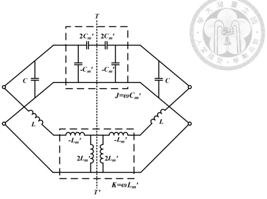
Figure 2.5 shows the equivalent circuit model for mixed coupling of resonators.
The L, C, L′ and m Cm′ are the self-inductance, self-capacitance, mutual inductance and mutual capacitance, respectively. The angular resonance frequency of uncoupled resonators is ω=1 LC . For analysis, the impedance inverter K= ωLm′ and admittance inverter J=ωCm′ are used to respectively replace the magnetic and electric coupling.
Fig. 2.5 The equivalent circuit model for mixed coupling of resonators
Fig. 2.6 The equivalent circuit model of I/O resonator with single loading.
By using the concept of inserting electric wall and magnetic wall into symmetry plane of the equivalent circuit, the resonance frequencies are
) )(
( 2
1
m m
e L L C C
f = − ′ − ′
π (2.22)
) )(
( 2
1
m m
m L L C C
f = + ′ + ′
π (2.23)
Then, the mixed coupling MX can be calculated by (2.22) and (2.23),
L C
i
s GS11
m m
m m
m e
m e
X LC L C
C L L C f f
f M f
′ + ′
+ ′
= ′ +
= 2 − 2
2 2
(2.24)
2.2.3. External Quality Factor Qe
For extracting external quality factor Qe of the input/output (I/O) resonator, the equivalent circuit is shown in Fig. 2.6. The G can be the external conductance of lossless LC resonator. The reflection coefficient S11 at the excitation port of resonator is
G Y
G Y Y
G Y S G
in in
in in
+
= − +
= −
1 1
11 (2.25)
where Yin in the input admittance of the resonator
−
= +
=
ω ω ω
ω ω ω
ω 0
0 0
1 j C
L C j
j
Yin (2.26)
Theω0 =1 LC is the resonance frequency. By lettingω=ω0+∆ω and using an approximation(ω −ω02) ω≈2∆ω
2 , the Yin can be written as
0 0
2 ω
ω
ω ∆
= j C
Yin (2.27)
The S11 can be represented by (2.27) and
Q
e= ω
0C G
) 2
( 1
) 2
( 1
0 0 11
ω ω
ω ω
∆
⋅ +
∆
⋅
= −
e e
jQ
S jQ (2.28)
When the resonator is assumed lossless, the magnitude of S11 is equal to 1. The phase of S11 changes with frequency. Figure 2.7 shows the phase response of S11 versus the functionω ω0. When the phase is ±90°, the Δω is found to be
Fig. 2.7 Phase response of S11.
1 2
0 m =m
∆ ω
ω
Qe (2.29)
The absolute bandwidth between the ±90°points is
Qe 0 90
ω ω ω
ω = ∆ −∆ =
∆ ± o + − (2.30)
Thus, the external quality factor can be extracted by
90o
0
∆ ±
= ω
ω
Qe (2.31)
In practical filter design, the external quality factor can be extracted by group delay of S11. The S11 is rewritten as
2φ 11
e
jS =
− (2.32)where
∆
= −
0
1 2
tan ω
φ Qe ω
(2.33) The group delay of S11 is given by
(
0)
20 1 2
1 4
) 2 ) (
11( ω ω ω ω
ω φ
τ + ∆
⋅
=
∂
−
−∂
=
e e
S Q
Q
(2.34)
At resonance Δω=0, the maximum value of group delay is
0 0
) 4
11( ω
ω
τ e
S
Q
= (2.35)
So, the external quality factor can be obtained by
4 ) ( 0 0
11
ω ω
τ ⋅
=
S
Qe (2.36)
2.3. Basic Theory of Acoustic Wave Resonator [18][68][69]
The acoustic wave resonators consist of a slab of piezoelectric material layer and metal layer, known as electrodes, for applying an exciting voltage. For surface acoustic wave (SAW) resonators, the electrode with interdigital structure on the top of piezoelectric layer has been used to transmit the wave along the horizontal direction of the piezoelectric slab. For bulk acoustic wave (BAW) resonators, the electrodes are on the both sides of piezoelectric layers. The acoustic wave propagates through the piezoelectric slab in the vertical direction. The structure of SAW/BAW resonators are shown in Fig. 2.8. There are two types of BAW resonators: film bulk acoustic wave resonators (FBAR) and solidly mounted resonators (SMR). The major difference between FBARs and SMRs is the structure below the bottom electrode. There is an air-gap cavity in the FBARs and Bragg reflectors in the SMRs. The structure of FBAR and SMR resonators are shown in Fig. 2.9.
The piezoelectric effect is induced by the slab of piezoelectric material. The piezoelectricity describes the energy interchange between electrical and mechanical energy. The piezoelectricity includes two kinds of effects, i.e., direct piezoelectric effect
(a) (b)
Fig. 2.8 Structure of SAW/BAW resonators, (a) SAW resonator (b) BAW resonator. [67]
(a) (b)
Fig. 2.9 Structure of FABR and SMR resonators, (a) FBAR resonator (b) SMR resonator. [17]
and inverse piezoelectric effect. For direct piezoelectric effect, an electric field on the material is induced when a certain force or pressure is applied on the piezoelectric material. When a voltage is applied to excite the electric field, the stresses and strains are produced on the material.
The piezoelectric materials can be categorized roughly into single crystal, thin film, polymer and ceramic. For single crystal, there are quartz, LiNbO3 and LiTaO3, usually used for SAW resonators. For thin film, such as zinc oxide (ZnO) and aluminum nitride (AlN) are usually used for FBARs. In ceramic, the lead zirconate titanate (PZT) is another common used material.
Port 1
Port 2
IDT
Piezoelectric substrate
![Table 2.1 Brief summary of the mechanical wave equations and the electromagnetic equations [68]](https://thumb-ap.123doks.com/thumbv2/9libinfo/9597029.628132/48.892.166.782.112.827/table-brief-summary-mechanical-wave-equations-electromagnetic-equations.webp)