國立陽明交通大學 網路工程研究所
碩士論文
Institute of Network Engineering
National Yang Ming Chiao Tung University Master Thesis Dissertation
ScratchTalk:開源物聯網程式教育平台
ScratchTalk: An Open-source Programming Education Platform with IoT
研究生:温子翔 (Wen, Zih-Xiang) 指導教授:林一平 (Lin, Yi-Bing)
張明峰 (Chang, Ming-Feng)
中華民國一一○年九月
September 2021
ScratchTalk:開源物聯網程式教育平台
ScratchTalk: An Open-source Programming Education Platform with IoT
研 究 生:温子翔 Student:Zih-Xiang Wen
指導教授:林一平 教授 張明峰 教授
Advisors:Yi-Bing Lin Ming-Feng Chang
國立陽明交通大學 網路工程研究所
碩士論文
A Thesis
Submitted to Institute of Network Engineering College of Computer Science
National Yang Ming Chiao Tung University in partial Fulfillment of the Requirements
for the Degree of Master
in
Computer Science
September 2021 Taiwan, Republic of China
中華民國 一一○年九月
i
ScratchTalk:開源物聯網程式教育平台
學生:温子翔 指導教授:林一平 教授
張明峰 教授
國立陽明交通大學網路工程研究所碩士班
摘 要
現今全球對於程式設計的教育課程愈趨重要,學生學習程式的年齡也下降至國中及 國小。然而,傳統的程式設計課程僅用教學文字編輯器或相關編輯軟體教導學生如何撰 寫程式碼,使得學生容易在學習過程中缺乏樂趣而失去對於程式學習的熱忱。本碩論提 出一個網頁應用程式實作的程式設計教學平台—ScratchTalk,使用者只需要用電腦瀏 覽器開啟平台,無須安裝即可直接使用。此平台能夠讓使用者在不用寫程式碼的情況下,
利用 Scratch 積木的堆疊,訓練邏輯以及創造出多媒體程式應用,且當使用者利用 IoTtalk 擴充積木時,此平台會自動產生該專案的專屬 QR Code,當使用者利用智慧型 手機掃描 QR Code 後,系統會針對該課程自動建立手機及動畫之間的連線,之後即可使 用手機內建的感測器來控制 Scratch 動畫。上述功能利用物聯網的觀念來實踐,即是將 手機視為物聯網中的感測器,執行中的 Scratch 動畫視為執行器,使用者可運用此物聯 網特性製作出與物聯網結合的互動式遊戲。在此篇論文中,將描述系統如何使用以及運 作原理,詳細說明其細節,並且提出開源版本軟體,以提供工程師自由下載擴充其系統 功能。
關鍵字:物聯網、程式教育、Scratch、開源程式、感測器
ii
ScratchTalk: An Open-source Education Platform with IoT Student: Zih-Xiang Wen Advisors: Yi-Bing Lin
Ming-Feng Chang Institute of Network Engineering
National Yang Ming Chiao Tung University Abstract
Nowadays, programming education has become vital, and the age of students learning to program has also dropped to junior high and elementary schools. However, traditional programming courses teach students to write programs using text editors or Integrated Development Environment (IDE) for coding. The tedious learning process causes students to lose their enthusiasm for programming. This thesis proposes a web-based programming education platform—ScratchTalk. ScratchTalk enables users to create multi-media programs by building block stacks instead of writing code. In addition, when users use the extensions for IoTtalk in Scratch, ScratchTalk creates a QR code for the Scratch project. By scanning the QR code, users can send values of smartphone sensors to the Scratch project and thus interact with Scratch programs. In the IoT scenario, the smartphone is considered as a collection of sensors, and the Scratch animation program is a collection of actuators that takes actions according to the sensor values. In this thesis, we show how the system works and proposed an open-source version. Advanced programmers can download open-source ScratchTalk and extend the functionalities without limit.
Keywords: Internet of Things (IoT), Programming Education, Scratch, Open Source, Sensors
iii
誌 謝
這篇論文能夠順利完成,首先要感謝我的指導教授林一平老師在過程中給予許多非 常有幫助的建議與提醒,並且讓我能不受侷限的進行研究。特別感授謝旻錚教授,在我 的研究過程中,能夠在各方面給予我許多的意見及幫助,找出問題並有效解決,讓我的 研究能夠順利地進行,不吝給予評價與鼓勵,使我的論文更加嚴謹與完善。另外,我也 特別感大學時期指導我的謝許獻聰教授,我在他授課的網路概論以及專題研究中學習到 許多完成本篇論文所不可或缺的知識,同時也使我產生對網路及物聯網領域的興趣。除 了感謝各位教授,我也要感謝許多願意一起交流與成長的同學們。感謝實驗室同學彧豪、
昀諠、柏勛、冠文、尹睿、柏妍協助我尋找研究主題以及時常與我討論我遭遇的問題,
也特別感謝泰翔、峻頤、振淇學長耐心且無私地分享及提供許多技術上的協助。最後,
我要感謝所有給予我陪伴與鼓勵的摯友們,以及最支持我的家人們,若是沒有你們,我 將難以順利的完成學業。
時光匆匆流逝,我在陽明交通大學研究所的求學歷程,即將在新冠肺炎疫情的籠罩 之中略帶遺憾地結束了。感謝所有課堂上的教授及一起學習與玩樂的同儕,除了讓我留 下許多美好的回憶,也讓我慢慢朝著成為更有用的人邁進。我期許自己在未來的日子裡,
能夠善用這些年所學,在科技業界好好表現,也能對母校及社會做出貢獻。
温子翔 於 國立陽明交通大學網路工程研究所 中華民國 一一○年九月
iv
Contents
摘 要 ... i
Abstract ... ii
誌 謝 ... iii
Contents ... iv
List of Tables ... vi
List of Figures ... vii
Chapter 1. Introduction ... 1
Section 1.1. An Overview of IoTtalk ... 2
Section 1.2. ScratchTalk ... 4
Chapter 2. ScratchTalk ... 7
Section 2.1. Scratch ... 7
2.1.1. The Scratch Architecture ... 7
2.1.2. Scratch Extension System ... 10
Section 2.2. The IoTtalk Architecture ... 13
Section 2.3. The ScratchTalk Architecture ... 19
Chapter 3. ScratchTalk Graphical User Interface ... 23
Section 3.1. Components of User Interface ... 23
3.1.1. Navigation Bar ... 24
3.1.2. Code Tab ... 27
3.1.3. Paint Editor ... 30
3.1.4. Sound Editor ... 31
Section 3.2. The Scratch Extensions for IoTtalk ... 32
3.2.1. Scratch Blocks ... 32
3.2.2. The Scratch Blocks for IoTtalk ... 34
Chapter 4. ScratchTalk Subsystem ... 41
v
Section 4.1. ScratchTalk Procedures ... 41
4.1.1. The Initialization Procedure ... 42
4.1.2. The Login Procedure ... 43
4.1.3. The Logout Procedure ... 46
4.1.4. The Project Management Procedure... 47
Section 4.2. The Database System ... 51
4.2.1. The User Table ... 55
4.2.2. The AccessToken Table ... 58
4.2.3. The RefreshToken Table ... 60
4.2.4. The Project Table ... 61
Chapter 5. Open Source for IoTtalk ... 64
Section 5.1. Architecture ... 65
Section 5.2. Protocol ... 66
Section 5.3. Functionality ... 70
Chapter 6. Conclusion ... 73
Reference ... 76
vi
List of Tables
Table 4. 1 The User Table ... 56
Table 4. 2 The AccessToken Table ... 59
Table 4. 3 The RefreshToken Table ... 60
Table 4. 4 The Project Table ... 62
Table 5. 1 The supported functions for the open-source and commercial IoTtalk ... 71
vii
List of Figures
Figure 1. 1 Connections among IDFs and ODFs ... 3
Figure 1. 2 Software modules for the microphone to luminance mapping NA1 ... 4
Figure 1. 3 The IoTtalk project for a Scratch application ... 5
Figure 2. 1 The Scratch Architecture ... 8
Figure 2. 2 The Scratch GUI ... 8
Figure 2. 3 A JavaScript Example for a Scratch Extension ... 12
Figure 2. 4 The reporter block ... 12
Figure 2. 5 The IoTtalk Architecture ... 13
Figure 2. 6 The IoTtalk GUI ... 16
Figure 2. 7 Displaying sensor data in ScratchTalk project ... 18
Figure 2. 8 The IoTtalk project for a Scratch project ... 19
Figure 2. 9 The ScratchTalk Architecture ... 21
Figure 3. 1 The ScratchTalk GUI block diagram ... 23
Figure 3. 2 The ScratchTalk GUI ... 24
Figure 3. 3 The navigation bar of ScratchTalk GUI ... 24
Figure 3. 4 The drop-down menu for the “File” item ... 25
Figure 3. 5 The drop-down menu for the “Edit” item ... 26
Figure 3. 6 The QR code for IoTtalk connection ... 26
Figure 3. 7 The remote control webpage ... 27
Figure 3. 8 The “User profile” item and its drop-down menu ... 27
Figure 3. 9 The code tab ... 28
viii
Figure 3. 10 The Scratch extension library ... 29
Figure 3. 11 The added Scratch extension ... 30
Figure 3. 12 The paint editor ... 31
Figure 3. 13 The sound editor ... 32
Figure 3. 14 The Scratch blocks ... 34
Figure 3. 15 The hat block for IoTtalk ... 35
Figure 3. 16 The reporter block for IoTtalk ... 35
Figure 3. 17 The implementation of the Scratch extension for IoTtalk ... 39
Figure 3. 18 The stack block for IoTtalk ... 39
Figure 3. 19 An example project to control a smart lightbulb ... 40
Figure 4. 1 The ScratchTalk Subsystem block diagram ... 41
Figure 4. 2 The Initialization Procedure ... 42
Figure 4. 3 The Account Subsystem GUI ... 43
Figure 4. 4 The Login Procedure ... 44
Figure 4. 5 The Login page of the Account Subsystem GUI ... 45
Figure 4. 6 The Logout Procedure ... 46
Figure 4. 7 The Scratch extension for IoTtalk in the Scratch extension library ... 48
Figure 4. 8 The Project Management Procedure ... 48
Figure 4. 9 The IoTtalk project configuration in JSON format ... 50
Figure 4. 10 The ScratchTalk database system ... 52
Figure 4. 11 The JavaScript code for database connection... 53
Figure 4. 12 The JavaScript code for database synchronization ... 55
Figure 4. 13 The JavaScript code for the user model ... 57
ix
Figure 4. 14 The JavaScript code for the access token model ... 60
Figure 4. 15 The JavaScript code for the refresh token model ... 61
Figure 4. 16 The JavaScript code for the project model ... 63
Figure 5. 1 The open-source IoTtalk architecture ... 64
Figure 5. 2 A comparison of the IoTtalk network domain: (a) open-source version and (b) commercial version ... 66
Figure 5. 3 A comparison of the communication protocols used by devices in IoTtalk: (a) open-source version and (b) commercial IoTtalk ... 67
Figure 5. 4 The data flow between an input and an output device in open-source IoTtalk ... 68
Figure 5. 5 The data flow between an input and an output device in commercial IoTtalk ... 69
1
Chapter 1. Introduction
Nowadays, programming has become an essential skill for teenagers. Programming courses have also been compulsory for high school students in many countries. Initially, students were taught to learn programming languages using a text editor or simple Integrated Development Environment (IDE) with compilers that output the application’s result to the terminal. To students, purely output those alphanumeric characters on screens makes programming tedious. Therefore, more and more education programming platforms had been released. To inspire students’ creativity, some teachers decide to purchase specific development kits such as MCU board, LEGO robot, and Raspberry Pi together with sensors and actuators for students to operate. With these hardware devices, students are expected to create exciting applications that interact with the real world. However, establishing a programming learning environment mentioned above is expensive since computers with specific software or additional hardware are required in these approaches. Setting up own developing environment at home is also a difficult task for most students.
To resolve the above issues, we have developed ScratchTalk, a web-based education programming platform based on the open-source software, Scratch [1][2]. ScratchTalk is an application platform of an Internet of Things (IoT) development platform called IoTtalk [3].
Scratch enables programmers to create applications online, and IoTtalk provides robust connectivity between IoT devices. Thus, with ScratchTalk, programmers can build their interactive applications via web browsers in a simple manner. Some existing online platforms also support creations of interactive programs such as EduTalk [4]. However, ScratchTalk
2
aims to encourage children to learn to program where the children can get rid of writing alphabetic code. Instead, they build the application using block stacks [5] which is much easier and more fascinating. With the concept of IoT, the process of learning programming becomes much more interesting than ever. Programmers conveniently write programs to interact with IoT devices, such as smartphones, Arduino boards, and other IoT devices. This chapter introduces the IoTtalk system and then describes the ScratchTalk platform.
Section 1.1. An Overview of IoTtalk
IoTtalk is a platform that supports the rapid development of network application software to drive new sensors. IoTtalk characterizes an IoT device by its functionalities called device features (DFs). A device feature is defined as an input or output capability of an IoT device. Thus, each device may possess one or multiple device features. For instance, a smart barometer has an input device feature (IDF) called “Pressure,” and a lightbulb has an output device feature (ODF) called “Luminance.” A device model (DM) is a collection of device features to describe an actual IoT device. For example, a DM “Smartphone” with the acceleration sensor has an IDF called “Acceleration.” A device object (DO) is an instance of a device model representing a real IoT device. The connectivity of IoT devices is provided by a software called network application (NA). Network applications are responsible for receiving and sending data from/to IoT devices. While IoT devices connect to the network, NAs will then be established and executed in the IoTtalk system. Whenever an IDF updates a new value, the corresponding IoT device informs the NA to process the data and transmit the result to the target ODFs.
3
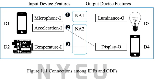
Figure 1.1 illustrates the relationships of the four IoT devices D1, D2, D3, and D4. D1 and D2 are the input IoT devices, whereas D3 and D4 work as output IoT devices. In the figure, the smartphone D1 has two IDFs, “Acceleration-I” and “Microphone-I.” The Arduino board D2 has one input device feature, “Temperature-I.” As illustrated on the right of Figure 1.1, the lightbulb D3 has an output device feature, “Luminance-O,” and the smartphone D4 has an ODF, “Display-O.”
Figure 1. 1 Connections among IDFs and ODFs
Figure 1.1 illustrates the interactions among the IoT devices as Lines (1) - (3). Each link connecting an IDF to an ODF represents the interactions between the corresponding device features in IoT devices. The interactions are implemented in programs called network applications (NAs). NA1 represents the network application that implements interactions (1) for D1 and D3. Identically, NA2 implements interactions (2) and (3) for D1, D2, and D4. Link (1) connects the Microphone IDF (the microphone sensor of D1) to the Luminance ODF (the luminance of D2). NA1 processes the microphone values sent from D1 and then controls the luminance on the lightbulb D4. Since a network application handles the individual device features independently, IoTtalk runs a software module for each device feature. The network
4
application can be constructed by including these reusable DF modules [6].
Figure 1.2 shows the details with DF modules for Link (1) in Figure 1.1. The network application NA1 handles the Microphone of D1 through the Microphone Module. The Mic-IDF Module processes the voice data received by the smartphone microphone sensor and passes the result to the Lum-ODF Module. After the ODF module translates the received value to the luminance value, NA1 outputs this value to the Luminance ODF to drive D3.
Figure 1. 2 Software modules for the microphone to luminance mapping NA1
Since the IDF and the ODF modules are independent, we can reuse these software modules to build network applications if the IoT devices have the same DFs. Thus, IoTtalk can speed up the development of IoT applications significantly.
Section 1.2. ScratchTalk
ScratchTalk is a web-based education programming platform consisting of two open-source projects, Scratch and IoTtalk. Scratch is a popular block-based visual programming language created by the Lifelong Kindergarten group at MIT Media Lab and is available for free download [7]. Scratch allows students to create their own interactive stories, games, and animations. IoTtalk provides connectivity between IoT devices. In ScratchTalk,
5
users may write Scratch programs using block stacks to render the Scratch animation in the browser without installing any software. To extend student’s learning experience with some real-world applications, ScratchTalk utilizes the IoT technology provided by IoTtalk. In these circumstances, users can interact with IoT devices instantly after creating their programs.
While programmers enter the ScratchTalk Graphical User Interface (GUI), a new Scratch project will be created to develop their applications. To set up the connection between the Scratch application and IoTtalk, programmers will have to add the IoTtalk related extension to their projects. After the addition, the Scratch application acts as an IoT actuator.
While users scan the QR code with their smartphones or tablets, the devices become the sensor/control devices to control the Scratch application on the GUI. In addition to working as an output IoT device, Scratch can also act as an input IoT device that generates values to control other devices such as a smart lightbulb.
Figure 1. 3 The IoTtalk project for a Scratch application
Provided that a programmer adds the IoTtalk extension to his/her Scratch project, IoTtalk automatically creates a corresponding project, as shown in Figure 1.3. In the figure, the smartphone D1 has two IDFs, “Orientation-I” and “Microphone-I.” The Scratch application D2 has three ODFs “Horizontal-O,” “Vertical-O,” and “Volume-O.” When a user
6
tilts their smartphone in this project, the smartphone’s orientation values determine the sprite’s movement on ScratchTalk GUI. The sprite may either move horizontally or vertically.
The IoTtalk server automatically generates a network application NA1 and NA2 to process the orientation and microphone value. When a user’s smartphone has scanned the QR code on the GUI, the smartphone (D1) registers itself as a remote control for this project, and the Scratch application (D2) registers itself as a cyber device. After the registration process, the IoTtalk server can automatically receive and send messages from/to these two IoT devices.
This thesis describes the design and implementation for ScratchTalk and is organized as follows. Chapter 2 illustrates the architecture for Scratch and ScratchTalk. In Chapter 3, we show how users operate the ScratchTalk GUI. Chapter 4 gives the implementation of the ScratchTalk Subsystem. For Chapter 5, we will introduce the open-source version of IoTtalk and discuss the difference between open-source and commercial IoTtalk. At last, Chapter 6 concludes the whole work.
7
Chapter 2. ScratchTalk
In this thesis, ScratchTalk is developed based on Scratch and IoTtalk (commercial version). The Scratch Extension System plays a vital role in bridging the two systems. It connects the Scratch to IoTtalk, thus enabling IoT devices to communicate with Scratch. In this chapter, Section 2.1 first introduces Scratch, including its system architecture and the Scratch Extension System. Section 2.2 describes the architecture of IoTtalk. This IoTtalk system is commercial software such that users cannot set up their own machines without an IoTtalk license. To resolve the issue, we released an open-source IoTtalk which will be described in detail in Chapter 5. Section 2.3 shows the architecture of ScratchTalk.
Section 2.1. Scratch
Scratch is a well-known visual language that enables students to create interactive games and animations. With the advent of the Scratch Extension System in Scratch 3.0, the extension module features make it possible for students to program physical devices and web services. Thus, IoT devices can communicate with Scratch through IoTtalk.
2.1.1. The Scratch Architecture
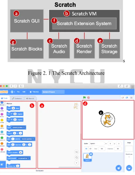
Figure 2.1 illustrates the architecture of the Scratch system. The Scratch Graphical User Interface (Scratch GUI; Figure 2.1 (a)) is a web page with the classic interface ported from desktops to the Internet. Programmers can interact with the GUI through web browsers on laptops, tablets, and smartphone devices. Figure 2.2 shows the web page of the Scratch GUI.
8
Each web page is a Scratch project for a programmer to build a Scratch application using Scratch blocks [8]. When a user first visits the Scratch GUI, the web page initializes an empty project without any script written in the code area (Figure 2.2 (a)). To build a Scratch application, users can drag the Scratch blocks from the block palette (Figure 2.2 (b)) to the code area. When the program starts, the sprite (Figure 2.2 (c)), an image to be controlled by scripts, will take action according to the created code.
s Figure 2. 1 The Scratch Architecture
Figure 2. 2 The Scratch GUI
The Scratch Virtual Machine (Figure 2.1 (b)) is the core engine of the Scratch system. It
9
is responsible for representing, running, and maintaining the internal states of computer programs written with Scratch blocks. The main works are the import/export of projects, extension management, GUI rendering, and state management. When a user imports a Scratch project file, the Scratch VM starts loading all the required components to the GUI. The loaded items include code, sprites, blocks, extensions, and audio players. The Scratch Audio (Figure 2.1 (c)) creates the audio players. When executing sound blocks in Scratch, the audio players play the corresponding sound effects. The Scratch Render (Figure 2.1 (d)) is a rendering engine based on WebGL [9]. It creates the sprites (Figure 2.2 (c)) according to the image data in SVG format or PNG format. The Scratch Render engine also updates the size, position, angle, effects, and layers of sprites components. While loading the Scratch Audio and Scratch Render resources, some files may not exist in the local disk. In such circumstances, the Scratch VM asks Scratch Storage (Figure 2.1 (e)) to download the required files from the cloud.
To export a project, the Scratch VM creates a JSON file to describe the project. Later, it packs the JSON file, audio files, and images into an “sb3” file. Scratch VM also manages the extension blocks. The Scratch Extension System (Figure 2.1 (f)) allows experienced programmers to implement new extensions to connect Scratch to hardware devices or access network resources such as Google Translate. Thus, IoT devices can interact with Scratch through IoTtalk. The extension blocks are defined in the Scratch Extension System and loaded to the GUI by Scratch VM. The Scratch Blocks (Figure 2.1 (g)) manages the code for every sprite and the extension utilized in the Scratch project. When users switch between the sprites, the Scratch GUI asks the Scratch Blocks component to return the corresponding code
10
to be displayed.
2.1.2. Scratch Extension System
The Scratch Extension System [10][10] is designed to allow experienced Scratch users and developers to expand Scratch language into new domains, e.g., interaction with LEGO WeDo and other IoT devices. At the core of this system are individual Scratch extensions—small sets of blocks that enable new functionalities in Scratch. The collection of extended blocks expands the Scratch vocabulary while adhering to the language grammar.
It enables Scratch projects to connect with external hardware (such as micro:bit), access sources of information on the Internet (such as Google Translate and Amazon Text to Speech), or implement more advanced functionalities. The extensions can be roughly classified into three categories as follows:
Hardware extensions: The hardware extensions support connecting Scratch with a wide range of hardware devices, such as the Arduino, LEGO, micro:bit, etc. This category forms the majority of the extensions created within the developer program.
Web-API extensions: The Web-API extensions utilize different types of web-APIs, e.g., an extension provided a block to get the weather of a certain location via an online API.
Pure JavaScript extensions: The pure JavaScript extensions take advantage of functionality built into JavaScript and HTML5 APIs. For example, a math block that calculates factorials. Another extension in this category adds blocks to process strings (e.g., convert a string to uppercase, reverse a string, etc.)
In Scratch 3.0, the Scratch programming platform goes online and can be accessed through browsers. Scratch 3.0 is implemented in React. The extensions are written in
11
JavaScript because browsers have easy access to JavaScript and because of its increasingly widespread use and wide range of powerful features. Each extension block is a JavaScript method invoked through a "bridge" layer implemented within Scratch. Figure 2.3 shows an example of the Scratch extension.
Line 1 class NewScratchExtension { Line 2 constructor (runtime) {
Line 3 this.runtime = runtime;
Line 4 } Line 5
Line 6 getInfo () { Line 7 return{
Line 8 id: 'newScratchExtension', Line 9 name: 'new extension blocks',
Line 10 blockIconURI:'data:image/png;base64,iVBO0…' Line 11 blocks: [
Line 12 {
Line 13 opcode: 'upperCaseConverter', Line 14 blockType: BlockType.REPORTER, Line 15 text: 'Original text: [TEXT]', Line 16 arguments: {
Line 17 TEXT: {
Line 18 type: ArgumentType.STRING, Line 19 defaultValue: 'text'
Line 20 } Line 21 } Line 22 } Line 23 ] Line 24 };
Line 25 } Line 26
Line 27 upperCaseConverter (args) {
12
Line 28 result = args.TEXT.toUpperCase();
Line 29 return result;
Line 30 } Line 31 } Line 32
Line 33 module.exports = NewScratchExtension;
Figure 2. 3 A JavaScript Example for a Scratch Extension
Figure 2. 4 The reporter block
A Scratch extension is implemented in the form of a class in JavaScript. Line 1 defines the class name of this extension. Lines 2-4 are the constructor function of this object. The constructor has to create the runtime object that stores information for later communication with the Scratch engine. Lines 6-25 illustrate the getInfo() function which all extensions must define. The function returns an object that contains the information needed for rendering both the blocks and the extension itself. Lines 8-10 are the basic information displayed on the GUI, such as id, name, and icon. Lines 11-23 contain an array that defines one or multiple blocks belonging to this extension. In this example, we create a reporter block for the extension. In Line 13, the opcode represents the method to be operated while the block gets triggered.
Namely, the method upperCaseConverter() defined in Lines 27-30 will be executed at that time. Line 14 defines the type of this block. Scratch provides several block types for different usages, such as HAT, COMMAND, and REPORTER. We will introduce the blocks in the next chapter. In this example, we create a reporter block that returns a value after executing the operation code. The returned result can either be a string or integer number. Line 15 sets the
13
text printed on the reporter block (as Figure 2.4). The “TEXT” closed by brackets is an argument that allows users to input information or even insert it with another reporter block.
Lines 16-20 determine the datatype and the default values of the arguments in a block. Finally, Lines 27-30 define the operation code method. In this case, it converts the “TEXT” argument to uppercase letters.
Section 2.2. The IoTtalk Architecture
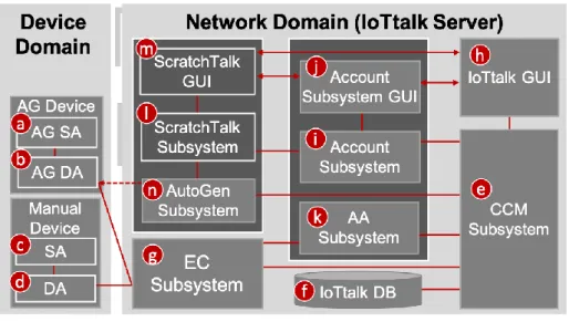
The IoTtalk is defined in two domains: device domain and network domain. The architecture of IoTtalk is shown in Figure 2.5.
Figure 2. 5 The IoTtalk Architecture
In the device domain, an IoTtalk device consists of two software components, Sensor and Actuator Application (SA) and Device Application (DA). The SA (Figure 2.5 (a)) implements the software executed in the IoT hardware device. It is responsible for implementing the IoT device functions such as the PM2.5 algorithm or the light intensity and color circuit software. The DA (Figure 2.5 (b)) is responsible for communications with the
14
network domain in the IoTtalk system. It mainly handles the registration process and data exchange via MQTT protocol carried by wired or wireless (i.e., Wi-Fi, 3G, or LTE) media.
While an IoT device attaches to the IoTtalk, the DA initiates a registration procedure to inform the IoTtalk server of the new connection. After registering successfully, the DA can start transmitting and receiving data. There are two categories of device applications, according to how we create them. The AG devices (Figure 2.5 (a) and (b)) can be automatically created by the AutoGen Subsystem (Figure 2.5 (j)), whereas the manual devices (Figure 2.5 (c) and (d)) should be created manually by users.
The network domain in IoTtalk is a well-modularized cloud server that manages network applications for IoTtalk devices. It consists of several subsystems and graphical user interfaces. The Creation, Configuration, and Management Subsystem (CCM; Figure 2.5 (e)) manages the features of IoT devices. It also automatically configures the connection between IDFs and ODFs. The configuration generated by CCM Subsystem will be stored in the IoTtalk database system (IoTtalk DB; Figure 2.5 (f)). The Execution and Control Subsystem (EC; Figure 2.5 (g)) is the core of the whole system. It is responsible for the control plane and the data plane of the connection between IoTtalk devices and the server. For the control plane, there are APIs implemented based on the MQTT protocol. DAs publish/subscribe to specific topics to send/retrieve the control messages for their DFs. In addition, if an IoT device connects/disconnects to/from IoTtalk, its DA informs EC to change its status to online or offline via the MQTT APIs. As for the data plane in EC, NAs will be created and executed for the connected IDFs and ODFs. The NAs first process the data received from IDFs with some functions or algorithms (e.g., normalization) and then deliver them to the connected ODFs.
15
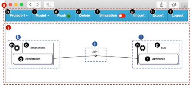
The IoTtalk Graphical User Interface (IoTtalk GUI, Figure 2.5 (h)) provides a friendly web-based user interface to quickly establish connections and meaningful interactions among the IoT devices. Figure 2.6 illustrates an example of the IoTtalk GUI. On the top of the interface window is a menu bar (Figure 2.6 (a)) with several functions (Figure 2.6 (b)-(i)).
Users can switch between IoTtalk projects by clicking the “Project” item (Figure 2.6 (a)). The
“Model” item is a drop-down list of device models. By selecting the DMs with their corresponding DFs, users may add the chosen DMs to the current projects. For example, in this project, the “Smartphone” and “Bulb” device models (Figure 2.6 (j) and (k)) are added.
The “Flush” item (Figure 2.6 (d)) is a toggle button to flush the states of the project when IoTtalk suspends the project due to wrong settings. The color of the “Flush” item indicates the status (green for "on", red for "off"). If a user clicks the green “Flush” button, the status will change to "off." After 5 seconds later, IoTtalk will automatically alter the status to "on" to complete the process of flushing. Users may press the “Delete” item (Figure 2.6 (e)) to delete the current IoTtalk project. To activate or deactivate the simulation function, users can toggle the “Simulation” item. After the activation, a simulator simulates a real IoT device and starts sending data. Users can effectively verify the correctness of their NA settings during the simulation. The “Import” item (Figure 2.6 (g)) and “Export” item (Figure 2.6 (h)) is used to import/export an IoTtalk project from/to a text file. The “Logout” item (Figure 2.6 (i)) is a button to sign out the current user.
16
Figure 2. 6 The IoTtalk GUI
The Graphical Layout Window (Figure 2.6 (j)) graphically shows the IoT devices and their connections. The graphical representation of an IoT device is called Device Object (DO) (see Figure 2.6 (k) and (l)). A device object is the graphical representation for an instance of the device models created in the GUI and can be mapped to a real IoT device. The device object consists of a device setting object (Figure 2.6 (m) and (n)), a device model name object (Figure 2.6 (o) and (p)), and several device feature (DF) objects (Figure 2.6 (q) and (r)). By clicking the setting object, the user can set up the parameters, save or delete the device object.
To attach real devices to the device objects, one can press the name objects. For connecting IDF objects with ODF objects, users can toggle the DF objects. All connections (Figure 2.6 (s)) specified in the Graphical Layout Window provide the data paths such that the data are transferred from the IDFs to the ODFs through these connections. The connections can be created by clicking a device feature object of an input device object followed by clicking the other one in the output device object.
17
The Account Subsystem (Figure 2.5 (i)) is a standalone system that manages the creation, deletion, and authentication of accounts for IoTtalk. To achieve the single sign-on (SSO) concept, the Account Subsystem provides OAuth [12] for access delegation. With the OAuth service, ScratchTalk Subsystem can effectively speed up the user registration and sign-in process. The Account Subsystem Graphical User Interface (Figure 2.5 (j)) is the web-based graphical interface for users to manage their accounts. The Authentication and Authorization Subsystem (AA; Figure 2.5 (k)) is responsible for managing users’ access to IoTtalk. While users attempt to manipulate the system, AA Subsystem checks if they have been authenticated and authorized. Every authorized user possesses a valid identity given by the AA Subsystem for future access in the IoTtalk system.
The AutoGen Subsystem (Figure 2.5 (n)) effectively integrates IoT with ScratchTalk Subsystem (Figure 2.5 (l)) by automatically generating devices and projects. Users can interact with their Scratch application through smartphones instantly.
The ScratchTalk Subsystem (Figure 2.5 (l)) is an application developed based on IoTtalk.
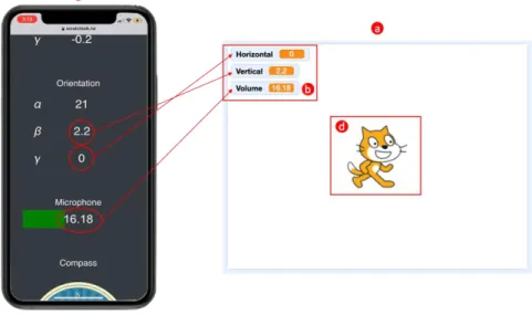
ScratchTalk is associated with a graphical user interface (ScratchTalk GUI; Figure 2.5 (m)) modified from the Scratch (Figure 2.1). In the ScratchTalk GUI, users can make creative Scratch projects with the functional blocks and interact with real IoT devices. Figure 2.7 shows an example of sending sensor data to ScratchTalk. Figure 2.7 (a) shows an area in the GUI called “stage.” It displays the visualized Scratch programs. In this Scratch project, users can find the variables shown in Figure 2.7 (b) changes according to the data captured by the smartphone (Figure 2.7 (c)). Tilting the smartphone in specific directions determines the
“Horizontal” and “Vertical” value. On the other hand, the “Volume” value indicates the
18
volume of voice received by the smartphone.
Figure 2. 7 Displaying sensor data in ScratchTalk project
When a user attempts to make a Scratch project to interact with real devices, they simply add the Scratch extension for IoTtalk (described in Section 3.2) to their Scratch project.
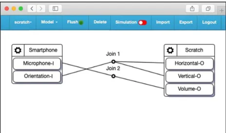
The ScratchTalk Subsystem (Figure 2.5 (l)) then informs AutoGen Subsystem to create an IoTtalk project for the Scratch project. Figure 2.8 illustrates the IoTtalk project configuration for a Scratch project. Figure 2.8 shows the IoTtalk project configuration for a Scratch project.
The “Smartphone” (Figure 2.8 (a)) is the input device model which implements the DA/SA for the smartphone device. The output device model “Scratch” (Figure 2.8 (b)) implements the DA/SA for the Scratch application. The Smartphone model has two IDFs, including Orientation-I and Microphone-I. Similarly, the Scratch model is composed of three ODFs:
Horizontal-O, Vertical-O, and Volume-O. Join 1 and Join 2 links handle the transmission of the orientation and microphone data, respectively. After receiving values, the SA for the Scratch can take action according to the program created by users.
19
Figure 2. 8 The IoTtalk project for a Scratch project
Section 2.3. The ScratchTalk Architecture
Figure 2.9 shows the ScratchTalk architecture. The ScratchTalk subsystem (Figure 2.9 (a)) is associated with a GUI based on Scratch. The ScratchTalk GUI (Figure 2.9 (b)) is modified from the Scratch (Figure 2.1). We modify the Scratch GUI (Figure 2.9 (c)) by adding new functions to support IoTtalk services, including the QR code for connecting smartphones to ScratchTalk. As for the Scratch VM (Figure 2.9 (d)), we define a few extensions which enable Scratch applications to connect with IoTtalk. We will describe the details of ScratchTalk GUI in Chapter 3. The ScratchTalk subsystem is a server that handles the communication between the Scratch VM and the AutoGen Subsystem (Figure 2.9 (e)).
The Scratch extension for IoTtalk can be added to a Scratch project manually or loaded according to the “.sb3” file automatically. The Scratch VM requests the ScratchTalk Subsystem that IoTtalk services to provide the corresponding IoTtalk project for the current Scratch project. The ScratchTalk Subsystem then tells the AutoGen Subsystem to create an
20
IoTtalk project related to the current Scratch project via HTTP/HTTPS requests. The Scratch VM also starts a process running as an IoTtalk DA and registers to EC Subsystem (Figure 2.9 (f)) for sending/receiving data to/from IoTtalk. The registration uses HTTP/HTTPS protocol, and the data transmission takes advantage of the MQTT protocol to send values in low latency.
Given security issues, merely authorized users are allowed to access IoTtalk services. The user authentication and authorization processes are done with the OAuth service provided by IoTtalk Account Subsystem (Figure 2.9 (g)). The ScratchTalk database (Figure 2.9 (h)) stores the user-related information, such as access token and ID token, for identification and access to user information from the OAuth server. The detailed database schema is described in Section 4.2.
21
Figure 2. 9 The ScratchTalk Architecture
In ScratchTalk Subsystem, there are three management procedures: login, logout, and project management. When a user attempts to log in or log out ScratchTalk, the login (Figure 2.9 (j)) or logout (Figure 2.9 (k)) procedure will be triggered. While logging in, the ScratchTalk Subsystem directs the user to the login page of the Account Subsystem GUI. The Account Subsystem authenticates the user and returns the user’s access token, ID token, and refresh token to the ScratchTalk Subsystem. For the logout procedure, the ScratchTalk Subsystem requests the Account Subsystem to revoke the access token of a user and changes the user’s status to offline.
The Project Management Procedure (Figure 2.9 (l)) is responsible for managing the Scratch projects and the IoTtalk projects. Every Scratch project with an extension for IoTtalk needs an IoTtalk project handling the data transmission between the IoT devices and the Scratch application. The Project Management Procedure creates the corresponding IoTtalk Project for such Scratch projects. When the user logs out of ScratchTalk or leaves the web page containing a Scratch project with an extension for IoTtalk, the corresponding IoTtalk project will be deleted because it is no longer needed.
The ScratchTalk Event Handler (Figure 2.9 (m)) is responsible for events dispatching between the ScratchTalk Subsystem components and the communications with ScratchTalk GUI, Scratch VM, Account Subsystem, and AutoGen Subsystem. For example, when a user adds the extensions for IoTtalk to a Scratch project, the ScratchTalk event handler requests the AutoGen Subsystem to set up an IoTtalk project and then informs the ScratchTalk GUI to
22
show the Scratch blocks for IoTtalk.
In the AutoGen subsystem, the AutoGen Event Handler (Figure 2.9 (n)) handles the interactions inside the AutoGen subsystem and the communication with the ScratchTalk Subsystem and the CCM Subsystem (Figure 2.9 (o)). The ScratchTalk HTTP services (Figure 2.9 (p)) manage all requests that ScratchTalk needs to send to the CCM Subsystem, such as IoTtalk project configuration and device attachment/detachment. When the AutoGen subsystem initializes, it executes the initiation program (Figure 2.9 (q)). The program triggers the ScratchTalk Subsystem initialization (Figure 2.9 (r)) and sets the URL of the ScratchTalk service based on the ScratchTalk URL Configuration File (Figure 2.9 (s)). As for the initialization in ScratchTalk Subsystem, the initiation program creates a connection to ScratchTalk DB and starts the ScratchTalk GUI server.
23
Chapter 3. ScratchTalk Graphical User Interface
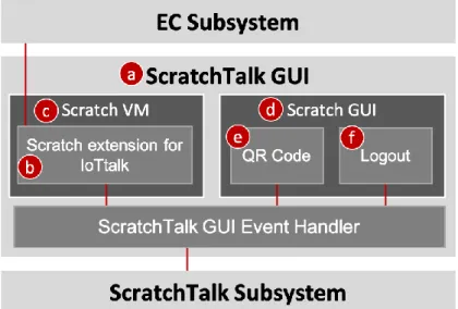
The ScratchTalk Graphical User Interface (ScratchTalk GUI; Figure 3.1 (a)) is a modification of the Scratch 3.0. We developed the Scratch extension for IoTtalk (Figure 3.1 (b)) to enable Scratch VM (Figure 3.1 (c)) to send and receive data through IoTtalk. In the Scratch GUI (Figure 3.1 (d)), we implemented a QR code (Figure 3.1 (e)) to provide hardware device connectivity and the logout function (Figure 3.1 (f)) for user access control. This chapter introduces the ScratchTalk GUI and a set of Scratch extensions for IoTtalk.
Figure 3. 1 The ScratchTalk GUI block diagram
Section 3.1. Components of User Interface
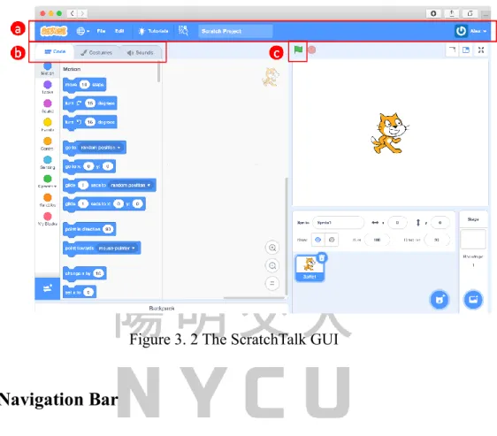
The ScratchTalk GUI (Figure 3.2) is a well-modularized front-end web interface implemented in React [15], a JavaScript framework. On top of the ScratchTalk GUI is the navigation bar (Figure 3.2 (a)) that allows users to visit any section within the website quickly.
Figure 3.2 (b) are the tabs to switch between the three components: the code tab, paint editor,
24
and sound editor. The details of the navigation bar and components mentioned above are described in the following subsections.
Figure 3. 2 The ScratchTalk GUI
3.1.1. Navigation Bar
The button with an Earth icon in the navigation bar (Figure 3.3 (a)) enables users to change the language of the GUI. If the chosen language is not supported for a component, the default language is displayed. For instance, the Scratch extension for IoTtalk supports English and Traditional Chinese. When a user selects other languages, the extension will be displayed in English by default.
Figure 3. 3 The navigation bar of ScratchTalk GUI
25
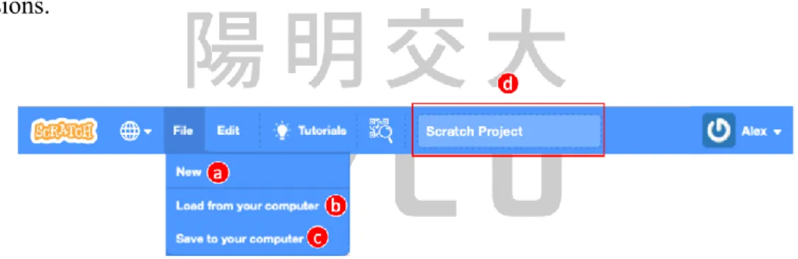
When a user clicks the “File” item (Figure 3.3 (b)), a drop-down menu shows the project files (Figure 3.4). Users may select to either create a new project (Figure 3.4 (a)), load a Scratch project file from their computer, or save the current project to the local disk. When creating a new project, the GUI discards the previous project. To avoid losing their projects, users must manually save them by clicking the “Save to your computer” button (Figure 3.4 (c)). The project will be saved as a file with the extension “sb3”, indicating it is a file for Scratch 3.0. The input field (Figure 3.4 (d)) specifies the file name. To load an existing project to the editor, users simply click the “Load from your computer” button (Figure 3.4 (b)). Files for the old version of Scratch are acceptable as well, such as the ones with “sb1” and “sb2”
file extensions.
Figure 3. 4 The drop-down menu for the “File” item
The “Edit” item (Figure 3.3 (c)) provides two functions: restore and turbo mode. If the project has recently removed one or more sprites, backdrops, costumes, or sounds, the
“Restore” button (Figure 3.5 (a)) can restore them. Once the “Restore” button is clicked, recently deleted assets will be restored in their usual spot. Then, the item turns light blue with the text “Restored.” Scratch provides a feature called “Turbo Mode” that makes the project run approximately 30 times faster. It is helpful for programs with fast execution, such as ones that use complex math formulas. However, it shifts resources from the display (such as sprite
26
motion on the stage) to computation (running code). Turbo Mode can be entered by clicking the “Turn on Turbo Mode” button (Figure 3.5 (b)) or by pressing the shift key and the Green Flag (Figure 3.2 (c)) simultaneously.
Figure 3. 5 The drop-down menu for the “Edit” item
Figure 3.3 (d) is the “QR code” item that we added to ScratchTalk GUI. The QR code is used for connecting IoT devices to IoTtalk. By toggling the “QR code” item, the GUI displays the QR code (Figure 3.6). The ScratchTalk Subsystem generates the QR code when a Scratch extension for IoTtalk is added to the Scratch project. After scanning the QR code with a smartphone or tablet, it opens a remote control web page (Figure 3.7) to interact with the current Scratch project. The browser shows the values of the sensors which will be sent to IoTtalk and passed to the Scratch application afterward.
Figure 3. 6 The QR code for IoTtalk connection
27
Figure 3. 7 The remote control webpage
The “User profile” item (see Figure 3.8 (a)) shows the username and photo to indicate that the user is online. When a user clicks the “User profile” item, a drop-down menu shows the “logout” button (Figure 3.8 (b)). The user can click the button to log out ScratchTalk.
Figure 3. 8 The “User profile” item and its drop-down menu
3.1.2. Code Tab
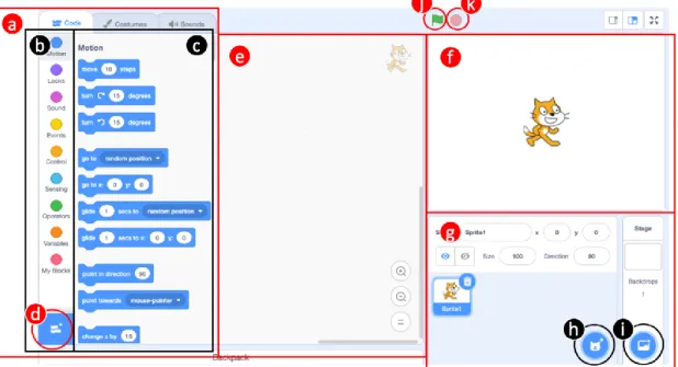
Figure 3.9 displays the code tab in the ScratchTalk GUI. The code tab contains several sections that can be used to code and run scripts and sprites. The block palette (Figure 3.9 (a))
28
is the area on the left side of the Code Tab. Figure 3.9 (b) contains the nine basic sections of blocks in Scratch. By selecting a section, the corresponding blocks are shown in Figure 3.9 (c).
Users can drag them to the code area (Figure 3.9 (e)) to write programs. The blue button in the bottom-left corner (Figure 3.9 (d)) allows programmers to add Scratch extensions to the block palette for coding. When a user clicks the button, the ScratchTalk GUI will display the Scratch extension library (Figure 3.10) for him/her to choose an extension. For instance, we add the LEGO extension (Figure 3.10 (a)) to our Scratch project. The added extension will be displayed as a section of blocks below the basic ones (see Figure 3.11 (a)).
Figure 3. 9 The code tab
The code area (Figure 3.9 (e)) stores the blocks that run the project. Programmers can drag blocks from the block palette to the code area and arrange them into scripts. To delete a block, users can either right-click the block or drag it back into the block palette. Each sprite has its scripts, and users can select the sprites in the sprite pane (Figure 3.9 (g)).
29
Sprites perform their actions in the stage (Figure 3.9 (f)) area. Users can modify the position of a sprite on the stage by script or manually drag them with a mouse.
Figure 3.9 (g) shows the sprite pane and stage pane. The sprite pane allows users to switch sprites, and the stage pane is used to change the backdrop of the stage. By switching the sprites, the user can view and modify the selected sprite script in the code area. Moreover, he/she can add new sprites and backdrops to the pane through Figure 3.9 (h) and (i).
The green flag button (Figure 3.9 (j)) is used to start the scripts in the project, and the stop sign (Figure 3.9 (k)) terminates all running processes when it is pressed.
Figure 3. 10 The Scratch extension library
30
Figure 3. 11 The added Scratch extension
3.1.3. Paint Editor
Figure 3.12 shows the paint editor. Users may switch the interface from the code tab to paint editor using the tabs shown in Figure 3.2 (b). There are some tools to customize sprites to perform actions on the stage. Users can draw with the brush, fill colors in an enclosed shape, or add a text box for the sprite.
31
Figure 3. 12 The paint editor
3.1.4. Sound Editor
In the block palette, Scratch provides a section of sound blocks that play/stop sound effects during the runtime of the Scratch application. Users can import and modify the sound effects in the Scratch sound editor (Figure 3.13. The editor provides functions to adjust the volume and speed. On the other hand, users can choose the fade-in and fade-out effect or even edit the length of the music.
32
Figure 3. 13 The sound editor
Section 3.2. The Scratch Extensions for IoTtalk
Owing to the launch of the Scratch extension system, programmers can connect external hardware devices to Scratch. ScratchTalk provides the Scratch extensions for IoTtalk to allow users to interact with Scratch applications through IoT devices. This section introduces the blocks in Scratch and shows the implementation of the extension for IoTtalk.
3.2.1. Scratch Blocks
Scratch Blocks are designed based on the Google Blockly [16] project that provides a design specification and codebase for building creative computing interfaces. With the Scratch Virtual Machine (VM) [17], users can quickly develop the visualization programs using the Scratch Blocks. Scratch Blocks brings two different programming grammars.
ScratchTalk adopts the standard Scratch syntax to snaps blocks vertically like LEGO bricks.
33
In contrast, in the ScratchJr [18] software for younger children, the blocks are snapped horizontally and labeled with icons instead of words.
According to the shape of the blocks, Scratch Blocks can be categorized into the following six groups:
Hat blocks: Hat blocks start scripts in Scratch projects. In Figure 3.14 (a), a hat block is shaped with a rounded top and a bump at the bottom. As a result, programmers can only place other blocks under it. The operation code of a hat block returns true or false. The Scratch Virtual Machine periodically checks if the return value of a hat block changes from true to false. When the condition happens, the hat block will be triggered and the blocks below it will start executing.
Stack blocks: Figure 3.14 (b) shows the stack blocks, also called command blocks. A stack block performs the main commands and controls the sprites in the ScratchTalk GUI stage.
A stack block has a notch at the top and a bump on the bottom. Therefore, users can place any block above or below a stack block.
Boolean blocks: A Boolean block (Figure 3.14 (c)) has a hexagonal shape. The block returns a true or false value of a condition.
Reporter blocks: A Reporter block (Figure 3.14 (d)) returns an integer or string value.
Unlike stack blocks, reporter blocks are shaped with rounded edges and cannot be placed directly above or below another block. Instead, they fit into a number, a text, or a drop-down input. When Scratch runs the block into which the reporter block has been placed, it will first run the reporter block script to determine its value before executing the external block.
34
C blocks: A C block is shown in Figure 3.14. The block takes the shape of the letter “C.” C blocks loop the blocks in Cs or check whether a condition is true.
Cap blocks: Cap blocks (Figure 3.14 (e)) terminate the scripts. A cap block has a notch at the top and a flat bottom. Consequently, users must not place any block below a cap block.
Figure 3. 14 The Scratch blocks
3.2.2. The Scratch Blocks for IoTtalk
Generally, the ScratchTalk GUI acts as an output IoT device, displaying data from IoTtalk and performing actions using the sprites. In this case, we designed a hat block and a reporter block in the Scratch extension for IoTtalk. Both blocks have the IoTtalk icon (see Figures 3.12 and 3.13). The hat block periodically runs its operation code to check whether the Scratch application receives any data from IoTtalk. When the condition changes to true from false, all the hat blocks of the extension for IoTtalk execute the blocks that stick to their bottom. Each hat block contains a drop-down list to select the ODFs of the Scratch application (see Figure 3.15). By selecting one of the ODFs, when the selected ODF receives data, the condition of the hat block becomes true. Setting to “any” indicates that when one of
35
the ODFs receives data, the hat blocks will execute the scripts below them.
Figure 3. 15 The hat block for IoTtalk
To obtain the data received by ODFs, users can utilize the reporter block in the extension for IoTtalk. As shown in Figure 3.16, the reporter block has a drop-down menu to specify which ODF value to present. In the menu, “Horizontal” represents the orientation value on the X-axis of an input IoT device. The value of “Horizontal” ranges from -180 to +180. Similarly, “Vertical” stands for orientation value on the Z-axis which ranges from -90 to +90. “Volume” indicates the volume of the voice received by the microphone sensor, and the value ranges from 0 to 30.
Figure 3. 16 The reporter block for IoTtalk
Figure 3.17 illustrates the implementation of the Scratch extension for IoTtalk. Line 1 begins to create the JavaScript class for the extension. In the constructor, Line 4 executes the execDA() function. The function creates an IoTtalk device application (DA) instance and registers the DA to IoTtalk. Lines 12-14 indicate the action to be performed when the green
36
flag (Figure 3.9 (j)) or the stop sign (Figure 3.9 (k)) on the GUI is clicked. Lines 27-42 show the implementation of the hat block for IoTtalk. The operation code of the hat block is written in Lines 72-82. The hat block periodically runs the operation code. The code returns a true or false value since a hat block can merely be trigger when the return value switches from false to true. Lines 43-57 define the reporter block, and Lines 93-99 show its operation code. The reporter block simply returns the received data of the selected device feature.
Line 1 class Scratch3IoTtalkBlocks { Line 2 constructor(runtime) { Line 3 this.runtime = runtime;
Line 4 this.execDa();
Line 5 this.whenNewDataArrived =
Line 6 this.whenNewDataArrived.bind(this);
Line 7
Line 8 var register = this.dai.register.bind(this.dai);
Line 9 var deregister =
Line 10 this.dai.deregister.bind(this.dai);
Line 11
Line 12 this.runtime.on('PROJECT_START', register);
Line 13 this.runtime.on('PROJECT_LOADED', register);
Line 14 this.runtime.on('PROJECT_STOP_ALL', deregister);
Line 15 } Line 16
Line 17 getInfo() { Line 18 return {
Line 19 id: 'iottalk',
Line 20 name: formatMessage({
Line 21 id: 'iottalk', Line 22 default: 'IoTtalk',
Line 23 description: 'IoTtalk extension' Line 24 }),
37
Line 25 blockIconURI: iconURI, Line 26 blocks: [
Line 27 {
Line 28 opcode: 'whenNewDataArrived', Line 29 blockType: BlockType.HAT, Line 30 text: formatMessage({
Line 31 id: 'iottalk.whenNewDataArrived',
Line 32 default: 'While I receive new data for Line 33 [onDataMenu]',
Line 34 description:'when an ODF receives data' Line 35 }),
Line 36 arguments: { Line 37 onDataMenu: {
Line 38 type: ArgumentType.STRING, Line 39 menu: "onDataMenu",
Line 40 }, Line 41 } Line 42 }, Line 43 {
Line 44 opcode: 'getData',
Line 45 blockType: BlockType.REPORTER, Line 46 text: formatMessage({
Line 47 id: 'iottalk.getData', Line 48 default: '[odfList] data',
Line 49 description: 'get value from an ODF' Line 50 }),
Line 51 arguments: { Line 52 odfList: {
Line 53 type: ArgumentType.STRING, Line 54 menu: "odfMenu",
Line 55 }, Line 56 } Line 57 }
38
Line 58 ],
Line 59 menus: {
Line 60 odfMenu: {
Line 61 acceptReporters: true, Line 62 items: this.ODF_MENU Line 63 },
Line 64 onDataMenu:{
Line 65 acceptReporters: true, Line 66 items: this.ONDATA_MENU Line 67 }
Line 68 }, Line 69 };
Line 70 } Line 71
Line 72 whenNewDataArrived(args){
Line 73 if (this.dai.odfData.get(args.onDataMenu)){
Line 74 if(new Date().getTime()-(this.dai.odfData.get(args Line 75 .onDataMenu)).timestamp < VALID_THRESHOLD){
Line 76 return true;
Line 77 } Line 78 else{
Line 79 return false;
Line 80 } Line 81 } Line 82 } Line 83
Line 84 getData(args){
Line 85 if(this.dai.getOdfData(args.odfList)[0]){
Line 86 return this.dai.getOdfData(args.odfList)[0];
Line 87 }else{
Line 88 return 0;
Line 89 } Line 90 }
39
Line 91 } Line 92
Line 93 module.exports = Scratch3IoTtalkBlocks;
Figure 3. 17 The implementation of the Scratch extension for IoTtalk
In another case, the Scratch application can be used as an input IoT device to control other devices. For example, we have customized an extension for a smart room. The blocks in the extension can control the IoT devices in the connected room. Figure 3.18 shows the stack block to control a smart light bulb. When the block executes, it sends the value from ScratchTalk GUI to the “Luminance” ODF of the light bulb. We should insert a value to be delivered into the textbox of the stack block (Figure 3.18 (a)). The value can be either a reporter block or a number. The drop-down menu (Figure 3.18 (b)) assigns the target ODF to which data should be sent. Figure 3.19 shows an example project to control the smart light bulb.
When the extension (Figure 3.19 (a)) is added to the Scratch project, the Scratch Virtual Machine will create a DA and register it to IoTtalk, thereby completing the connection between the Scratch application and the smart bulb. Figure 3.19 (b) is the script to control the light bulb device. When the stack block is triggered by the upper hat block, IoTtalk transmits the value in the stack block to the lightbulb (Figure 3.19 (c)). Then, the lightbulb adjusts its brightness according to the data.
Figure 3. 18 The stack block for IoTtalk
40
Figure 3. 19 An example project to control a smart lightbulb
41
Chapter 4. ScratchTalk Subsystem
The ScratchTalk Subsystem (Figure 4.1 (a)) manages three procedures to handle the communication between the ScratchTalk GUI and other subsystems in the IoTtalk network domain: Login, Logout, Project Management (see Figure 4.1 (b)-(d)). In ScratchTalk Subsystem, the Initialization procedure (Figure 4.1 (e)) is triggered by the Autogen Subsystem (Figure 4.1 (f)) to set up the ScratchTalk Subsystem and the ScratchTalk database (Figure 4.1 (g)). Events entering and leaving the ScratchTalk subsystem will be received and dispatched by the ScratchTalk Event Handler (Figure 4.1 (h)). Section 4.1 gives details of the initialization and the three management procedures. In Section 4.2, we will describe the database system and the database schema.
Figure 4. 1 The ScratchTalk Subsystem block diagram
Section 4.1. ScratchTalk Procedures
This section describes the ScratchTalk procedures, including the initialization procedure
42
and three management procedures.
4.1.1. The Initialization Procedure
The initialization procedure starts up the ScratchTalk subsystem as illustrated in Figure 4.2.
Figure 4. 2 The Initialization Procedure
Step 1: The init() function creates a database connection. We can choose either MySQL or
SQLite as the data storage.Step 2: The ScratchTalk Subsystem runs a command to start the ScratchTalk GUI server.
Step 3-4: The init() calls the syncDB() to synchronize the database with the ScratchTalk
settings. The syncDB() first checks if the connection has been successfully established. If the connection is created, the function creates the database tables which do not exist. For those tables that were not created correctly, the syncDB() will add or remove columns to repair them.43
The code of syncDB() is shown in Figure 4.12.
4.1.2. The Login Procedure
To ensure system security, ScratchTalk requires users to log in before they can access ScratchTalk. When a user clicks the “ScratchTalk” (Figure 4.3 (a)) on the Account Subsystem GUI to enter ScratchTalk, the user will be redirected to the ScratchTalk Subsystem to start the authentication and authorization. After obtaining authorization, users can start writing scripts on ScratchTalk GUI (Figure 4.1 (i)). Figure 4.4 illustrates the details of the login procedure.
Figure 4. 3 The Account Subsystem GUI
44
Figure 4. 4 The Login Procedure
Step 1-2: When the user presses the hyperlink of “ScratchTalk” on the Account Subsystem
GUI, the web browser directs him/her to the ScratchTalk Subsystem for authentication and authorization.Step 3-4: The authRedirect() redirects the user to the Account Subsystem GUI to log in.
Step 5: For users who have not yet logged in to the Account Subsystem with an IoTtalk
account, they need to enter a username and password, and then press the “Login” button (Figure 4.5 (a)). When the button is pressed, the Account Subsystem GUI sends the user information to the Account Subsystem for user authentication. On the other hand, users who have logged in before can skip entering their names and password. The Account Subsystem can authenticate the user through the session ID encapsulated in the HTTP/HTTPS packets.45
Figure 4. 5 The Login page of the Account Subsystem GUI
Step 6-7: The Account Subsystem authenticates the user. After the authentication, the user
will be redirected to ScratchTalk Subsystem with an authorization code.Step 8-11: The authCallback() asks the Account Subsystem to exchange the authorization
code for an access token, a refresh token, and an ID token. The access token represents the authorization of the ScratchTalk Subsystem to access specific parts of a user’s data in the Account Subsystem. Nevertheless, an access token has its expiration time. ScratchTalk should update an access token with the refresh token. An ID token is a JSON Web Token (JWT) [19]that encapsulates user information, signature, and the signature algorithm metadata in JSON format. The authCallback() decodes the ID token to get user information, such as name, email, etc.
Step 12-15: After obtaining the user information, the authCallback() function stores the
tokens and user profile in the tables of ScratchTalk DB.46
Step 16-17: At the end of the login procedure, the authCallback() redirects the user back to
ScratchTalk GUI.4.1.3. The Logout Procedure
To log out of ScratchTalk, the user clicks the “Logout” item (Figure 3.8 (b)) on the ScratchTalk GUI to trigger the logout procedure. Figure 4.6 illustrates the steps of the logout procedure.
Figure 4. 6 The Logout Procedure