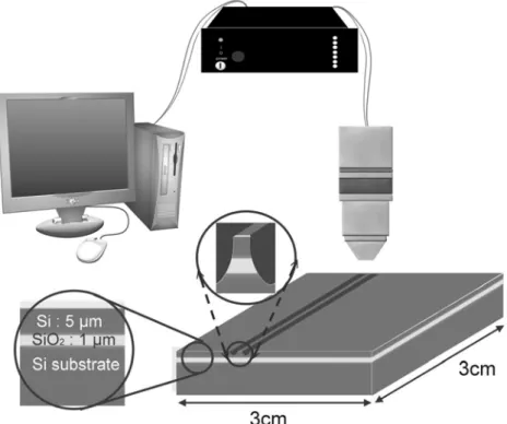
Laser Machining for SOI Wafer
32
0
0
全文
(2)
(3)
(4)
(5)
(6)
(7)
(8)
(9)
(10)
(11)
(12)
(13)
(14)
(15)
(16)
(18)
(19)
(20)
(21)
(22)
(23)
(24)
(25)
(26)
(27)
(28)
(29)
(30)
(31)
(32)
數據
+7
相關文件
In x 2 we describe a top-down construction approach for which prototype charge- qubit devices have been successfully fabricated (Dzurak et al. Array sites are de ned by
For ASTROD-GW arm length of 260 Gm (1.73 AU) the weak-light phase locking requirement is for 100 fW laser light to lock with an onboard laser oscillator. • Weak-light phase
Please liaise with the officer in your school who are responsible for the Class and Subject Details Survey for using of the same class names in both the Class and Subject
● tracking students' progress in the use of thinking routines and in the development of their writing ability using a variety.. of formative assessment tools
Create and present information and ideas for the purpose of sharing and exchanging by using information from different sources, in view of the needs of the audience.
Create and present information and ideas for the purpose of sharing and exchanging by using information from different sources, in view of the needs of the audience.
n Receiver Report: used to send reception statistics from those participants that receive but do not send them... The RTP Control
In accordance with the analysis of relevant experimental results carried in this research, it proves that the writing mechanism and its functions may improve the learning
