A Battery Charger with Maximum Power Point Tracking Function for Low-Power Photovoltaic
System Applications
Chun-Wei Lin Dept. of Electrical Engineering, Chung-Yuan Christian University, Taiwan Huang-Jen Chiu, Yu-Kang Lo, Ting-Peng Lee,
Qing Su Chen, Wen Long Yu, Jian-Xing Lee Dept. of Electronic Engineering,
National Taiwan University of Science and Technology
Jian-Min Wang Dept. of Vehicle Engineering, National Formosa University, Taiwan
Frank Shih Macroblock, Inc., Taiwan
Abstract—
A battery charger with MPPT function for low-power PV system applications is presented in this study. For effective miniaturization, the battery charger is designed with high frequency operation. Some current-sensing techniques are studied, and their MPPT implementation is compared. A pulse charging method is also designed to prolong battery lifetime. The operation principles and design considerations of the proposed PV charger are analyzed and discussed in detail. A laboratory prototype is implemented and tested to verify the feasibility of the proposed scheme. Experimental results show that high MPPT accuracy and conversion efficiency can be simultaneously achieved under high frequency operation.
Keywords- Battery Charger, Low-Power PV System, Pulse Charging, MPPT Accuracy, Conversion Efficiency
I. I
NTRODUCTIONIn recent years, the growing concern over environmental issues has brought about great interest and remarkable investments in photovoltaic (PV) technology.
Compared with other renewable energy sources, PV systems have numerous advantages such as clean electricity generation, high reliability, little maintenance and no audible noise due to the absence of moving parts [1-3]. Stand-alone PV systems are commonly used in low-power applications such as LED lighting. The output power of PV arrays is always changing with solar irradiation conditions and atmospheric temperature. An MPPT control is usually applied to extract maximum power from the PV arrays. Hall-effect sensors are commonly used to sense PV array current for MPPT implementation. However, a hall-effect sensor with high bandwidth feature is too expensive and huge for low- power PV system applications. Meanwhile, a current-sensing resistor method has the merits of high linear quality, low cost and simple configuration. However, the power dissipation in current-sensing resistor brings about a thermal problem that is undesirable in miniaturizing a PV system. In this paper, a novel current-sensing method which uses the drain-source on- resistance R
ds(on)of the power MOSFET is studied for MPPT implementation. Some performance comparisons among various current sensing techniques using Hall-effect sensor, current-sensing resistor and drain-source on-resistance R
ds(on)for low-power PV system applications are analyzed and
discussed. Moreover, an auxiliary energy storage device such as lead-acid battery is necessary to improve the dynamic and steady-state performance for the stand-alone PV system. The lead-acid battery has low cost and high capacity features and is widely used in various applications such as uninterruptible power system (UPS), automotive power system and telecom power supply, among others. However, poor energy density characteristics, charging time and lifetime encumber commercial applications. Some charging methods such as constant voltage (CV) charging, constant current (CC) charging, CC/CV two-phase charging and pulse charging are commonly used for various battery charging systems. The CV and CC charging methods have the simplest control algorithms but shorten the battery lifetime due to their over- current or overcharging problems. In this paper, performance comparisons between a conventional CC/CV two-phase charging and a novel pulse charging methods will be studied for lead-acid battery in low-power PV system applications.
II. SYSTEM DESCRIPTION
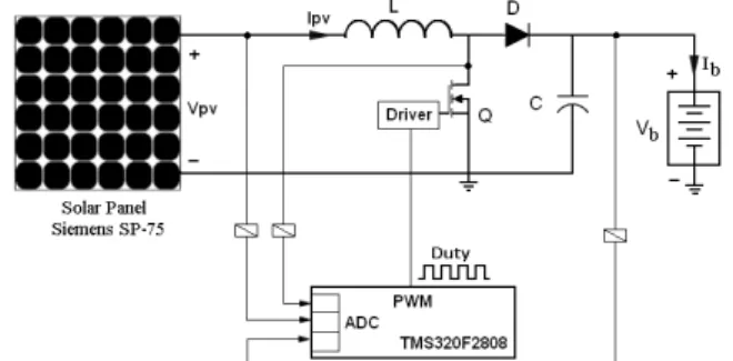
A block diagram of the studied PV charger is shown in Figure 1. The MPP tracking can be achieved by connecting a DC/DC converter between the PV array and battery stack.
MPPT algorithm for PV array and battery charging scheme are both implemented in a DSP controller. PV array voltage and current are sensed by the DSP controller to calculate the PV array power and directly control the power converter duty cycle. The battery voltage is also fed back to predict the state of charge (SOC) of the battery in determining its appropriate charging mode.
Figure 1 Studied battery charger with MPPT function for low-power PV system applications
A current-sensing technique by using a Hall-effect sensor that is commonly used for MPPT implementation in high-power PV system applications. The Hall-effect sensor has the advantages of high accuracy and high noise immunity.
However, it is too expensive and huge for low-power applications. Another current-sensing technique by using a simple resistor R
sensehas both high linear quality and low cost.
Power dissipation on current-sensing resistor causes a thermal problem that is undesirable for miniaturizing a PV system in low-power applications. In this paper, a current-sensing technique is studied by using the drain-source on-resistance R
ds(on) of power MOSFET. It is more suitable for low-power PV system applications because there is no extra-resistive sensing loss so that the PV system can be miniaturized significantly.
Some parameters including conversion efficiency η
eff, MPPT accuracy η
mpptand overall efficiency η
overallare regularly used to evaluate the electrical performance of the DC/DC converter with MPPT function as follows:
in eff
P
o= P
η (1)
m pv mppt
P
pvP
,
=
η (2)
mppt eff overall
= η × η
η (3)
where P
oand P
indenote the output power and input power of the DC/DC converter while P
pvand P
pv,mrepresent the actual output power and maximum output power of the PV array.
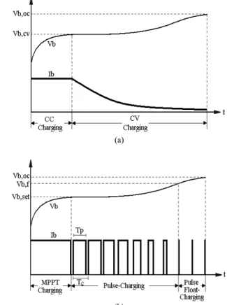
Figure 2(a) shows the conventional CC/CV two-phase charging scheme. At the beginning of charging process, a CC charging scheme with MPPT function is adopted to avoid the occurrence of over-current problems due to low battery voltage. As the battery voltage rises to a preset voltage V
b,cv, the MPPT function is disabled and a CV charging scheme is used to prevent overcharging problem. The CC/CV two-phase charging method has some drawbacks as follows:
1) Battery current sensing is necessary to implement CC charging. The charging performance depends on the accuracy and reliability of the used current sensor.
2) During CV charging period, MPPT function must be disabled to avoid overcharging problems.
3) As shown in Figure 2(a), the continued electrolyte reaction during the charging process brings about shortening the battery lifetime.
In this paper, a new pulse-charging method for low- power PV system applications is studied, as shown in Figure 2(b). When the battery voltage stays less than the preset level V
b,set, the MPPT charging proceeds. When the battery voltage rises to V
b,set, a pulse charging current is sent to battery. MPPT control remains during the charging period T
pwhile electrolyte reaction of battery is relaxed during the rest period.
The battery voltage V
bis sensed to determine the pulse width of battery charging current. When the battery voltage V
breaches V
b,f, a pulse current with a fixed narrow width is sent to float-charge the battery. For the studied pulse-charging method, no other sensor for battery current is needed. The
addition of rest period can relax the electrolyte reaction and prolong the battery lifetime.
(a)
(b)
Figure 2 a) Conventional two-phase charging and b) the proposed pulse charging methods.
III. DESIGN CONSIDERATIONS
The aim of this paper is to study the battery charger for low-power PV system applications. The design considerations for battery charging schemes, MPPT algorithm, power circuit and PV current sensing techniques will be described and discussed in detail as follows:
A. Battery Charging Design
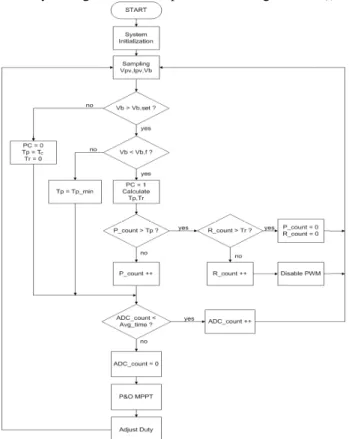
Figure 3 shows the flowchart of the studied pulse charging method. The battery voltage V
bis noted to determine the charging mode while the PV array voltage V
pvand current I
pvare noted to implement MPP tracking as follows:
1) When the battery voltage V
bis lower than the preset level V
b,set, the pulse charging control flag (PC) is reset to “0”
and the pulse charging function is disabled. During this charging mode, MPPT algorithm is carried out to extract the maximum power output of the PV array.
2) When the battery voltage V
bis higher than V
b,set, the control flag PC is set to “1” and the pulse charging function is enabled. The charging period T
pand rest period T
rof battery current is determined by calculating Equations (4) and (5).
( )
( ) ⎥ ⎥ ⎦
⎤
⎢ ⎢
⎣
⎡ ×
−
−
− −
−
=
cset b, f b,
b p b
p
T
V V
k V k k V
T k
T [ ] [ 1 ] 0 . 9
] 1 [ ]
[ (4)
p c
r
T T
T = − (5)
where T
p[k] and T
p[k-1] are the charging period at the sampling times k and k-1, respectively. V
b,fdenotes the preset float-charging voltage and V
b,setis the preset voltage level for pulse charging. V
b[k] and V
b[k-1] represent the sampling battery voltage at times k and k-1.
3) When the charging period counter P
_countis less than the calculated charging period T
p, it will accumulate to continue the MPP tracking. As the P
_countcounts to T
p, the rest period counter R
_countbegins accumulating. The PWM signal is disabled till the counter R
_countequals T
r. When the reset period is ended, the counters P
_countand R
_countare both reset. The charging period T
pand rest period T
rof battery current are then recalculated.
4) As long as the battery voltage V
bis higher than the preset float-charging voltage V
b,f, the pulse width of charging current is set as the minimum pulse width T
p_min. During the charging period, MPP tracking is remained for float- charging the battery. This period will be terminated as the battery voltage reaches the preset overcharge level V
oc.
Figure 3 Flowchart of the studied pulse charging method
As mentioned above, the pulse width of charging current supplied by the studied PV charger is determined by the battery voltage. MPP tracking is retained during the charging period to raise the utility of PV array. The electrolyte reaction can be relaxed during the reset period to prolong the battery lifetime.
B. MPPT Algorithm
As mentioned in Section I, an MPPT algorithm that provides high accuracy tracking is needed. For the low-power PV system studied in this paper, a Perturb and Observe (P&O) method which has some important advantages such as simplicity and good performance is adopted. The control
algorithm is shown in Figure 4. The PV array voltage V[k]
and array current I[k] are sampled and used to calculate the instantaneous PV array power P[k]. The power obtained in the next iteration P[k+1] is compared with the power calculated in the previous iteration P[k]. In addition, the PV array voltage V[k+1] at the next iteration is compared with the previous PV array voltage V[k] to determine whether the converter duty cycle should be increased or decreased to reach the MPP.
Figure 4 Flowchart of the adopted MPPT algorithm
C. Power Circuit Design
The PV voltage in the practical implementation is between 7V to 17V for typical climate conditions and the nominal battery voltage is equal to 24V to allow for the power circuit in boost operation. The switching-frequency is designed as equal to 300kHz for circuit miniaturization. The continuous current conduction mode (CCM) operation is considered in the selection of the power inductor L as follows:
fs Ipv
D L Vpv
×
= ×
Δ (6)
where △I
pvdenotes the PV current ripple that is usually equal to 10% of rated current. The output filter capacitor C can be determined by Equation (7) as follows:
fs Vo
D C Io
×
= ×
Δ (7)
where △V
ois the voltage ripple which is usually equal to 1%
of the nominal battery voltage. In this paper, the Texas
Instruments DSP chip TMS320F2808 which has 16-bit PWM,
12-bit ADC and 100 MIPS is used to realize the digital
controller of the studied PV charger. Figure 5 shows the DSP
control diagram. The internal PWM counter is used to
generate PWM signal. The PV array current is sampled by
using a PWM interruption. The duty cycle of the PWM signal
is determined according to the battery charging control and the MPPT algorithm with ADC sampling average.
Figure 5 DSP control diagram
D. Current-Sensing Design
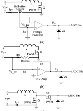
Figure 6(a) shows the current-sensing circuit by using a Hall-effect sensor. The Hall-effect sensor has a current attenuation ratio A
iand can convert the PV array current I
pvto a voltage signal V
s_pvby using a simple resistor R
pas follows:
i p
s_pv pv
R
A
V = I (8)
The voltage signal V
s_pvis then sent to ADC pin of the DSP chip via a voltage follower to avoid loading effect. A current-limiting resistor R
sand a 3.3V zener diode Z
care added to protect the ADC pin of DSP chip. The current- sensing technique with Hall-effect sensor has high noise immunity, but it is too expensive for the studied low-power applications. The bandwidth of a commercial Hall-effect sensor is usually not high enough such that the implemented MPPT accuracy may deteriorate under high-frequency operation. Figure 6(b) shows the current-sensing circuit by using a current sensing resistor. The PV array current I
pvcan be converted to a negative voltage signal V
s_pvby a simple resistor R
senseas follows:
sense pv
s_pv
I R
V = − (9)
The voltage signal V
s_pvis then sent to ADC pin of the DSP chip via an inverting amplifier (INV Amp) with a negative voltage gain (-R2/R1). It can be observed from Figure 6(b) that a sensed error for PV array voltage V
pvmay occur due to the addition of a current-sensing resistor R
senseas follows:
sense pv pv sen
pv,
V I R
V = − (10)
where V
pv,senand V
pvare the sensed and actual PV array voltages. For example, by using a current-sensing resistor R
senseof 0.22 Ω , the MPPT accuracy will deteriorate about 2%
under an operation condition with PV array voltage V
pvof 7V and PV array power P
pvof 4W. The sensed voltage error problem can be solved as long as the calculation for the instantaneous PV array power is compensated with the considerations of PV array current. The current-sensing resistor technique possesses both high linear quality and low cost. However, power dissipation on current-sensing resistor brings about the thermal problem that is undesirable in miniaturizing a PV system in low-power applications. In this paper, a new current-sensing circuit is studied by using the drain-source on-resistance R
ds(on)of power MOSFET as shown in Figure 6(c). The drain-source voltage V
ds(on)is sensed during on-state via a sampling transistor Q
s. A 3.3V zener diode Z
cis added to protect the ADC pin of DSP chip. The
V
ds(on)can be used to represent the PV array current I
pvas follows:
V
ds(on)= I
pvR
ds(on)(11)
It is obvious that the MPPT performance will be strongly related to the variations of the drain-source on- resistance R
ds(on)shown in Figure 7. The characteristic consideration of R
ds(on)is important for the power MOSFET selection. There is no extra-resistive sensing loss for R
ds(on)current-sensing technique so that the PV system can be miniaturized significantly and suitable for low-power applications.
(a)
(b)
(c)
Figure 6 a) Hall-effect sensor b) current-sensing resistor and c) Rds(on) current- sensing circuits
Figure 7 Drain-source on-resistance variations
IV. EXPERIMENTAL VERIFICATIONS
A laboratory prototype for the studied PV charger is
designed and tested to verify the feasibility of the proposed
schemes. The maximum power of the prototype circuit is
25W. The switching frequency is designed at 300kHz for
circuit miniaturization. Based on the design equations (6) and
(7), the power choke L is the 47 μ H SMD inductor and the
output filter capacitor C is 10 μ F. Two 12V/7Ah batteries are
series-connected to serve as the load of the designed prototype
circuit. The overcharge voltage V
oc, the float-charging voltage
V
b_f, and the pulse charging voltage for V
b_setare set at 27.6V,
27.3V and 26.4V, respectively in accordance with the battery
manufacturer’s suggestions. Thee current sensing techniques shown in Figure 8 are tested and compared for MPPT tracking of PV array. A commercial Hall-effect sensor LA 100-P with a current attenuation ratio of 2000:1 is used in experiments for current-sensing circuit as shown in Figure 6(a). LA 100-P is very popular for industrial applications due to its high noise immunity even though its bandwidth is only 200kHz. For another current-sensing circuit shown in Figure 6(b), a 0.22 Ω resistor R
senseis used to sense the PV array current. The voltage V
s_pvis amplified by an inverting amplifier with a voltage gain of -10 before it is sent to the ADC pin of DSP chip. For the third current-sensing circuit shown in Figure 6(c), the PV array current is sensed directly by using the power MOSFET with R
ds(on)of 0.22 Ω . Figure 8(a) shows the measured waveforms for MPP tracking by using the drain- source on-resistance R
ds(on)under 7V PV array voltage (at maximum power point of 4.08W) while Figure 8(b) demonstrates the measured MPPT waveforms under 17V PV array voltage (at maximum power point of 24.08W). It can be observed that the actual tracked powers are 3.88W and 23.6W, respectively.
(a)
(b)
Figure 8 MPPT waveforms by using Rds(on) under a) Vpv=7V and b) Vpv=17V
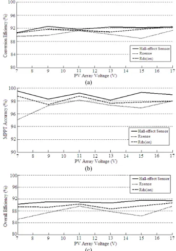
Figure 9 shows the measured conversion efficiency η
eff, MPPT accuracy η
mppt, and overall efficiency η
overallby using the studied three current-sensing techniques. Highest conversion efficiency and MPPT accuracy features can be achieved by using the Hall-effect sensor. However, the Hall- effect sensors are usually too expensive and huge so they are not suitable for low-power PV system applications. By using current-sensing resistor, the overall efficiency becomes the worst for the prototype circuit. The extra power loss and thermal dissipation on the current-sensing resistor result to lower conversion efficiency while a sensed error for PV array
voltage mentioned in Section III worsen MPPT accuracy.
Therefore, the studied current-sensing technique, which uses the drain-source on-resistance R
ds(on)of the power MOSFET will be the best choice considering the system cost, circuit miniaturization and overall efficiency.
(a)
(b)
(c)
Figure 9 Measured a) conversion efficiency b) MPPT accuracy and c) overall efficiency
Figure 10 shows the measured waveforms in the studied pulse-current charging scheme. During the charging period, the MPPT operation is retained in the studied PV charger. The measured accuracy is approximately 97.63%.
The MPPT function is disabled and the electrolyte reaction of battery stack can be relaxed during the reset period. The instantaneous PV power and duty cycle of the power switch at the end of the previous charging period are recorded and applied to the beginning of the next charging period. Thus, a high MPPT accuracy can be maintained for the studied pulse- current charging scheme.
Figure 10 Measured pulse-current charging waveforms
V. CONCLUSION
In this paper, a novel battery charger for low-power PV system applications is studied. The operation principles and design considerations for the studied PV charger were analyzed and discussed in detail. A laboratory prototype was designed and tested at a switching frequency of 300kHz to verify the feasibility of the studied scheme. Three current- sensing techniques namely those that use the Hall-effect sensor, the current-sensing resistor R
senseand the drain-source on-resistance R
ds(on)of power MOSFET were tested and compared for MPPT implementation. For the considerations of system cost, circuit miniaturization and overall efficiency, the studied R
ds(on)current-sensing technique has good performance. A pulse-current charging method with MPPT function was also studied and tested. The electrolyte reaction of battery stack can be relaxed to prolong the lifetime without the use of extra battery current sensor. The studied PV charger with MPPT function is especially suitable for the
implementation of a DC/DC module directly mounted on a single solar panel in low power applications.
ACKNOWLEDGMENT
The authors would like to acknowledge the financial support of the Macroblock, Inc. and National Science Council of Taiwan through grant number NSC 96-2628-E-011-115- MY3.
REFERENCE
[1] B. Sahan, A. N. Vergara, N. Henze, and A. Engler, P. A.
Zacharias, “Single-Stage PV Module Integrated Converter Based on a Low-Power Current-Source Inverter,” IEEE Trans.
Industrial Electronics, vol. 55, no. 7, pp. 2602-2609, July. 2008.
[2] Mohibullah, Imdadullah, and I. Ashraf, “Estimation of CO2 Mitigation Potential through Renewable Energy Generation,”
IEEE PECon’06, pp.24-29, Nov. 2006.