國立臺灣大學工學院機械工程學系 碩士論文
Department of Mechanical Engineering College of Engineering
National Taiwan University Master Thesis
具理想化特性之一般彈簧的最小跨越空間、佈線 與路徑配置合成
Routing Configuration Synthesis of Conventional Springs with ZFL characteristics for Minimizing Spanning Space
and Placing Spring
歐俞亨 Yu-Heng Ou
指導教授:陳達仁 博士 Advisor: Dar-Zen Chen, Ph.D.
中華民國 105 年 7 月 July, 2016
doi:10.6342/NTU201601711
I
摘要
本論文呈現一種方法使一般彈簧可以擁有零自由長度(ZFL)之理想特性,
並提出明確的彈簧佈線方式使其能夠安裝於機構之上,另外,也提出一種基於空 間再利用的彈簧路徑配置合成法。本文之模型是將彈簧-線組合安裝於一個串聯 式機械手臂的兩個獨立桿件之間,根據彈簧的作用將其劃分成三個區域,用於安 裝彈簧、拉伸彈簧和佈線。一旦安裝區有足夠的長度,彈簧便可以展現理想特性,
針對佈線區:為了盡可能減少彈簧-線組之長度,理論中以桿件上最接近彈簧接 點之距離做為參考指標,如此便可以清楚地表示出所有安裝條件下的彈簧-線組 所需長度。由於過長的安裝區將會阻礙機構的運動,因此本文提供一套捲線機構,
使得安裝區長度能縮短並合理地安裝於桿件上。另一方面,彈簧的拉伸區以一套 路徑配置合成法展現,彈簧在替換成不同彈簧和接點位置後仍能夠提供相同的關 節扭矩,卻占據更少空間;搭配捲線的方法,使得替換後的複數彈簧可以用一條 彈簧取代,並展現相同特性。最佳化的路徑配置評估方式採用兩種參數:彈簧面 積縮減率及彈簧貼伏程度,當彈簧佔用較小的空間,同時具備較高的貼伏度,便 可以得到最佳化路徑配置。搭配上述方法,彈簧在機械手臂上的配置便可以全面 地設計。本文在最後一節以一個串聯式三關節機械手臂的彈簧配置做為設計案例。
關鍵字:一般彈簧,捲線機構,路徑配置合成,串聯機械手臂,向量疊加
doi:10.6342/NTU201601711
II
Abstract
A methodology to develop tension springs with zero-free-length (ZFL)
characteristics is presented, and the configurations for placing the springs precisely on the manipulators are introduced. Also, this paper proposes a general design approach for the routing configuration synthesis of the springs on the basis of the re-utilization of spring space. A spring–string arrangement installed between two separate links of a serial-type manipulator is employed and is divided into three regions for mounting, tensioning, and placing springs. The springs can develop ZFL characteristics if adequate length is ensured for mounting the springs. To shorten the length for placing springs, a reference length acquired from the link configurations is utilized. The minimization of the placing length can therefore be described clearly. Because the overextended springs and links resulting from the longish mounting length shroud the workspace of the other links, the springs are reorganized using cable-driven
mechanisms to shorten the mounting length. The springs can then be arranged in alignment on the links. On the other hand, the proposed routing configuration synthesis are that one spring can be replaced by equivalent springs with consistent spring capability of the joint torque but occupy less spring space during motion. Wire winding technique of the springs is applied by using one equivalent sole springs for reducing the use of equivalent springs in routing configurations. Furthermore, the
doi:10.6342/NTU201601711
III
spring elongations are given a symbiosis relationship in wire winding so the spring coefficients can then be decreased. The assessments of the routing configuration synthesis by the shrinkage performance of spring space are provided. The optimized routing configuration is observed when the springs occupy least space, and align on the linkage, from which, the spring configuration can be readily obtained. The suggested configuration with and without wire winding is the scissor type. As achieved with these arrangements, comprehensive spring configurations on the manipulators can be shown. The routing configurations of the springs of a serial tri- articular manipulator are therefore illustrated as a design example in the last section.
Keywords:conventional spring, cable driven mechanism, routing configuration synthesis, serial manipulator, superposition of vector, conservation law
doi:10.6342/NTU201601711
IV
TABLE OF CONTENTS
CHAPTER 1 Intorduction ... 1
1.1 Background ... 1
1.2 Overview of related works ... 2
1.3 Motivation and preview ... 5
CHAPTER 2 Parameters of link and spring configurations ... 8
2.1 Link and spring configurations ... 8
2.2 Joint torques of springs on manipulators ... 11
CHAPTER 3 Mounting region : practical spring configurations on manipulators ... 13
3.1 Methodology of spring configurations for ZFL characteristics ... 13
3.2 Cable-driven mechanism of spring on the basis of pulley systems... 15
3.3 Cable-driven mechanism of spring on the basis of the reels ... 18
CHAPTER 4 Placing region : Spring configurations for minimizing the placing length 20 4.1 Determination of pseudo mounting length ... 20
4.2 Minimized placing length ... 23
CHAPTER 5 Extension region : Routing configuration synthesis ... 26
5.1 Superposition property of articulated springs ... 26
5.2 Routing configuration synthesis on the basis of equivalent articulated springs ... 28
5.3 Routing configuration synthesis of articulated springs by wire winding ... 34
5.4 Classifications and types of routing configurations ... 37
5.5 Optimize arrangements of spring space with routing configuration synthesis ... 40
CHAPTER 6 Optimize spring arrangements with illustrated examples ... 44
6.1 Optimized routing configuration synthesis of a serial tri-articular manipulator ... 44
6.2 Spring configurations for illustrated examples from ideal to practical ... 47
6.3 Applications of the routing configurations and the reel in existed manipulator ... 53
CHAPTER 7 Conclusions ... 55
References ... 57
doi:10.6342/NTU201601711
V
LIST OF FIGURES
Fig. 1 Spring attached between links 𝑖 and 𝑘 of the kinematic chain ... 9
Fig. 2 The spring configuration of the serial manipulator ... 12
Fig. 3 Spring elongation and its workspace (in gray blocks) in three cases ... 15
Fig. 4 Cable driven mechanisms with pulley systems for the springs ... 17
Fig. 5 Cable driven mechanism with the reel for the spring ... 19
Fig. 6 Mounting length and pseudo-mounting length of springs on the adjacent links ... 20
Fig. 7 Mounting length and pseudo-mounting length of springs on the proximal link ... 22
Fig. 8 The illustrated model for the superposition property of spring attachment vectors .... 27
Fig. 9 The routing configuration synthesis of the springs by two steps ... 29
Fig. 10 The possible solutions of spring configurations on the basis of graphical method ... 32
Fig. 11 The routing configuration synthesis of the springs with the wire winding technique by an equivalent sole spring. ... 34
Fig. 12 The exploded view of the articular springs with multi-part and mono-part ... 38
Fig. 13 The shrinkage performance of routing configurations w/ and w/o wire winding ... 41
Fig. 14 The alignment performance of the routing configurations ... 42
Fig. 15 The composite performance of the routing configurations w/ and w/o wire winding . 43 Fig. 16 The spring arrangements before and after routing configuration synthesis ... 45
Fig. 17 Practical configurations of the individual spring for ZFL characteristics ... 50
Fig. 18 The practical spring configurations by the use of the reels ... 50
Fig. 19 The refits of the bi-articular manipulator ... 54
doi:10.6342/NTU201601711
VI
LIST OF TABLES
Table 1 The pseudo-mounting length of springs on the basis of the mounting sides and the attachment links with the springs aligned or not aligned ... 23 Table 2 Placing length equations of springs on the basis of the mounting sides and
the attachment links ... 24 Table 3 The number and configurations of auxiliary links for virtual link ... 27 Table 4 Criteria of the routing configuration synthesis for articulated manipulator .. 33 Table 5 The classifications and types of the routing configurations of the springs .... 39 Table 6 Theoretical configurations and parameters of the springs ... 44 Table 7 The attachment vectors and spring coefficients of the manipulator with
routing configuration synthesis ... 47 Table 8 Practical configurations of the springs with the use of the reels ... 52 Table 9 The applications of the routing configurations and of the reels ... 53
doi:10.6342/NTU201601711
1
CHAPTER 1
Introduction
1.1 Background
Springs are elastic elements and are used widely in manipulators that facilitate controllability and utilization of energy. For tension springs, the physical length is the length at its initial state without any external force, whereas the free length is the length when the spring is unloaded and is shorter than physical length in preload springs.
However, the initial force and length in preload springs cannot be eliminated; therefore, the springs in this paper are assumed to be nonpreloaded. The physical length of a nonpreloaded springs is equivalent to its free lengths. The concept underlying zero-free- length (ZFL) springs is that the free length of a spring is eliminated and therefore the pull exerted by the spring is always proportional to the spring length, which is the sum of its free length and the elongation of the spring. Researches about the configurations of the springs for ZFL characteristics exist, but many limitations of the spring are neglected. So, a practical method for deriving feasible spring configurations for ZFL characteristics is required. Theorems [1-4] to derive configuration arrangements of the ZFL spring on manipulators show the powerful tools for accurately calculating the
doi:10.6342/NTU201601711
2
spring configurations. With these theorems, the spring configurations for manipulators are established. However, the aforementioned theorems neglect the physical limitations of the springs and linkages. For instance, the overextended links used for arranging springs may shroud the workspace of other links. The springs with long attachment length which occupy the space between the springs and linkages may also eliminate the advantages of the serial manipulators. Which are waited to be solved.
1.2 Overview of related works
1.2.1 Applications of tension springs in manipulators
Applications of tension springs in manipulators have been developed over the last century. Acclaimed designs introduced in the 1930s include the “Anglepoise Lamp” [5], which uses conventional springs by enabling adjustment of the initial tension in the springs. The development of design theorems based on ZFL tension springs began in the 1960s with the introduction of the first perfect equilibrator and the use of parallelogram linkages [6] for multiple–degrees of freedom (DOF) manipulators. Similarly,
pantograph linkages [7-9] were developed to enhance spring–manipulator interaction.
As elastic elements, ZFL tension springs were utilized for spring-to-spring balancing [10, 11] as well. The concept focused on the spring itself, the load on which could be varied in energy-free adjustment steps. Springs were classified as balancer and storage springs in this concept.
doi:10.6342/NTU201601711
3
1.2.2 Configurations of springs for Zero-Free-Length Characteristics
The pulley and wire arrangement has been widely applied in research and engineering applications. Approaches to arranging springs for ZFL characteristics started in the 1930s with the use of guiding elements and pulley–string arrangements [12, 13] to provide additional mounting space to the springs. However, systematic arrangement theorems were yet to be developed. Straightforward methods involving linkages, such as a slider or a cam [14, 15], were developed, but these methods have limitations. The arrangements derived in [16] shows intelligible means to achieve ZFL characteristics, but these arrangements do not consider the spring and string lengths.
Also, the elongation equation represented in [17] does not account for spring configurations. The limitations of the spring elongation are neglected by the
aforementioned approaches by using guiding elements and pulley–string arrangements.
Such methods might not be practicable because the springs are arranged through trial and error or by providing excessive spring mounting space. Moreover, the placing length of the springs between the mounting and tensioning springs is ignored.
Therefore, a practical method for deriving feasible spring configurations for ZFL characteristics is required.
1.2.3 Theorems to derive configuration arrangements of springs
Theorems to derive configuration arrangements of ZFL tension springs for
doi:10.6342/NTU201601711
4
manipulators exist, such as the technique for statically balancing any planar revolute- jointed linkage [3] or using stiffness block matrices for arranging springs on
manipulators [1, 2, 18]. In addition, spring installation configurations can be determined on the basis of the stiffness block matrixes [4]. By deriving and applying spring
configurations for ZFL characteristics, the rationality and feasibility of these applications and theorems can be established.
1.2.4 Spring adjustments
An energy-free adjustment method of the springs for gravity equilibrator is introduced [19] by changing the attachment positions of the tension springs or rubber springs on the linkages. The utilizations of multiple sets of spring-wire-pulley
arrangements simultaneously are also introduced [20]. The use of multiple sets of spring-wire-pulley arrangements aims to share the loading. On the other hand, cable- driven mechanisms with the use of the pulleys and reels [11, 21, 22], are discussed. The wire in that paper are utilized for eliminating the effect of wrap angle while using pulleys. Which is a technique can be further applied to the springs for reducing the spring coefficients. These researches provide diverse arrangements of the springs.
However, the methods to reduce the spring space in the manipulators, or to arrange the springs on the manipulators with optimized configurations are neglected.
doi:10.6342/NTU201601711
5
1.3 Motivation and preview
Traditionally, springs are arranged through trial and error or excessive mounting space for inducing ZFL characteristics to the springs. In this paper, a methodology for exactly inducing ZFL characteristics in conventional springs to serial manipulator is presented, and the compressive arrangements for mounting spring on manipulators with unrestricted motion is discussed. Which are the first issue of the paper. For the second issue, methods to reduce the spring space in the manipulators are neglected. To enhance the advantage of the serial manipulators with respect to the previous researches, a routing configuration synthesis for reorganizing the springs with less spring space and aligning on the manipulators is given. So, a spring can be arranged on the manipulators from theorem to practical.
In Chapter 2, a spring–string arrangement is employed and is divided into three regions for mounting, tensioning, and placing springs. And the joint torque provided by the spring can be derived.
In Chapter 3, the derivation of the spring configurations for developing ZFL characteristics as well as the applications of pulley and cable driven mechanisms are discussed. ZFL characteristics can be induced if adequate length can be ensured for mounting the spring according to the spring configuration. Although the spring configurations for ZFL characteristics are presented, feasible configurations and
doi:10.6342/NTU201601711
6
unlimited mounting length for the springs with respect to the links are yet to be achieved because the overextended springs and links caused by the long mounting length shroud the workspace of the other links. Because the mounting length is solved as a function of spring elongation, by the use of pulleys and reels, the elongation and mounting length can be shortened. The springs can then be arranged in alignment on the links. The spring configuration by this additional arrangement shows that a
comprehensive spring configuration exists. Theoretical springs can then be arranged practically on the manipulators.
In Chapter 4, the length for placing springs is determined on the basis of the spring configuration. To optimize the placing length, a reference length acquired from the link configurations is utilized. The springs are assumed to be arranged on the specific links;
hence, the placing lengths can be controlled, and minimization of the placing length can therefore be described clearly.
In Chapter 5, to further adjust the configuration of springs in the regions for tensioning springs, a general approach for re-utilizing the spring space on manipulators, so called routing configuration synthesis, is discussed. And the assessment of the routing configurations by shrinkage performance of the spring space is provided. The proposed routing configuration synthesis can provide consistent performance of spring torque but occupy less space of the springs during motion. And the springs are thereby
doi:10.6342/NTU201601711
7
replaced by equivalent springs derived from the routing configuration synthesis. The method of the configurations is based on the superposition approach of vectors, and the conservation law of spring capability in joint torques. Constraints for deriving the routing configurations are developed with the foregoing two concepts. By incorporating the constraints of vectors and energy, general solutions of the routing configurations of the springs can be proposed. And design equations of the spring coefficients or
attachment vectors of the equivalent springs can be derived. To further reduce the use of the equivalent springs in the routing configurations, wire winding technique of the springs is then applied by using one equivalent sole springs. Following by the
distributive law of spring elongation, the wire winding for the routing configurations is then established. The optimized routing configuration is observed when the springs occupy least space, and align on the linkage, from which, the spring configuration can be readily obtained.
In Chapter 6, an example illustrating the routing configuration synthesis of the springs of a serial three-articular manipulator is discussed. Thereafter, the derivations of the spring configurations for developing ZFL characteristics as well as the applications of pulley and reels are discussed.
doi:10.6342/NTU201601711
8
CHAPTER 2
Parameters of link and spring configurations
2.1 Link and spring configurations
A serial-type planar articulated manipulator with rigid multiple links is shown in
Fig. 1(a). Each succeeding link 𝑖+1 is connected to its preceding link 𝑖 by joint 𝐽𝑖. Link 𝑘 is the distal link and link 𝑖 is the proximal link closer to the ground link.
Configuration parameters are defined in this section, and each link vector
𝒓𝒊, 𝒓𝒋, … and 𝒓𝒌 of the articulated manipulator is placed along the line passing through
centers of the joints of links 𝑖, 𝑗, and 𝑘, respectively, and link vectors are represented by 2 × 1 matrices. Residual link length is the length from the link joints to the proximal and distal ends of the link and is represented by 𝑟𝑖𝑝 and 𝑟𝑖𝑑, respectively. The
succeeding link 𝑖+1 with respect to its preceding link 𝑖 can be represented using a 2 × 2
rotation matrix with joint angle 𝜃𝑖+1, where 𝜃𝑖+1 is measured counterclockwise from 𝒓𝒊 to 𝒓𝒊+𝟏. One mean is used to describe the links between link 𝑖 and 𝑘 as a virtual
link 𝑣, which is variable in length, with link vector 𝒗 from 𝐽𝑖 to 𝐽𝑘−1, that is, 𝒗 = 𝒓𝒊+𝟏+ ⋯ + 𝒓𝒋+ ⋯ + 𝒓𝒌−𝟏.
doi:10.6342/NTU201601711
9
(a) Link configurations
(b) Spring configurations
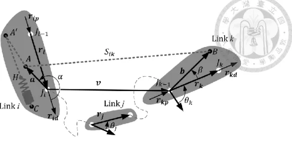
Fig. 1 Spring attached between links 𝑖 and 𝑘 of the kinematic chain
In Fig. 1(b), a tension spring is labeled 𝑆𝑖𝑘, free length as 𝑙𝑓, and string length as 𝑙𝑠. The two ends are hinged to links 𝑖 and 𝑘, and the spring coefficient is 𝑘𝑖𝑘. Springs
are distinguished by the number of joints that a spring spans over. If links 𝑖 and 𝑘 are contiguous, the spring is a mono-articular spring; otherwise, it is a multi-articular spring.
In the spring–string arrangement shown in Fig. 1(b), the point 𝐻 is fixed on the
doi:10.6342/NTU201601711
10
spring for arranging strings or wires; points 𝐴, 𝐴′, and 𝐵 are fixed on the links. The point 𝐴 is a turning point, and 𝐴′ is a pseudo-turning point dividing the spring into three regions, as shown in Fig. 1(b). The first region is called the “mounting region”
with mounting length 𝑚; it contains the spring and a part of the string. The second is the “extension region” between separate links in a serial-type manipulator with
extension 𝑥 during motion, which includes the remainder of the string. The turning points are not immutable. The mounting region can be arranged on the distal side such as link 𝑘 to obtain the turning point and the pseudo-turning as 𝐵 and 𝐵′, respectively.
Furthermore, the mounting region can be arranged elastically on the other links. The third region is the “placing region,” represented by 𝑝, is the distance between the two
turning points or the two aforementioned regions. The placing length of the spring can be theoretically expressed using Eqs. (1a) and (1b) when the spring is arranged on the
proximal and distal side of the manipulator, respectively.
𝑝 = 𝐴′𝐴̅̅̅̅̅ (1a)
𝑝 = 𝐵′𝐵̅̅̅̅̅ (1b)
Under tension, the length of a tension spring equals the sum of its free length and
elongation. Therefore, the length of the spring–string arrangement can be calculated, i.e.
𝛿 + 𝑙𝑓+ 𝑙𝑠. By the sum of regions’ lengths and the placing length, that is, 𝑥 + 𝑚 + 𝑝,
the elongation equation for a tension springs is derived and expressed in Eq. (2).
doi:10.6342/NTU201601711
11
𝛿 = 𝑥 + 𝑚 + 𝑝 − 𝑙𝑓− 𝑙𝑠 (2)
The extension 𝑥 is determined by the link kinematics and described as a function of link vectors 𝒗 and attachment vectors 𝒂, 𝒃. Attachment vectors are used to describe
the positions of points 𝐴 and 𝐵 with respect to the link joints 𝐽𝑖, and 𝐽𝑘−1. α and 𝛽 are the rotation angles of the attachment vectors measured counterclockwise from 𝒓𝒊, 𝒓𝒌 to 𝒂, 𝒃, respectively. 𝒂 and 𝒃 can be represented by the rotation matrices such
as 𝐑(α) = [cosα −sinαsinα cosα], 𝐑(𝛽) = [cos𝛽 −sin𝛽
sin𝛽 cos𝛽 ] and the unit vectors of links, that is, 𝒂 = 𝑎𝐑(α)𝒓̂𝒊, 𝒃 = 𝑏𝐑(𝛽)𝒓̂𝒌. Joint angle 𝜃𝑎𝑣, 𝜃𝑣𝑏 and 𝜃𝑎𝑏 are measured
counterclockwise from 𝒂 to 𝒗, 𝒗 to 𝒃 and 𝒂 to 𝒃 respectively.
2.2 Joint torques of springs on manipulators
By tensioning the springs, a force based on the spring coefficient and the spring elongation will be provide, i.e. 𝑘𝛿. And then, the spring force introduce torque to each spanned joint in Fig. 2. The joint torque can be presented by the function of the force and a perpendicular distance of the force to joints 𝑃 as Eq. (3a) shows. With the link kinematics are determined, the perpendicular distance can therefore be calculated as a component of the attachment vectors, and the joint torques 𝜏𝑎𝑣 and 𝜏𝑏𝑣 on the virtual link are herein derived in Eqs. (3b) and (3c), respectively. The negative value represents the clockwise direction.
doi:10.6342/NTU201601711
12
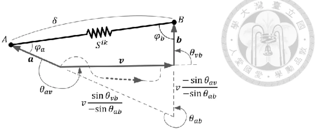
Fig. 2 The spring configuration of the serial manipulator
In Eqs (3), the joint torques are shown as the function of spring coefficients, attachment vectors and joint angles. Because sine terms are the variables during link
motion, consistent torque performance of the springs on each joint will be shown if 𝑘𝑎𝑏, 𝑘𝑎𝑣, 𝑘𝑏𝑣 are constant. These terms are the maximum joint torques that a spring can provide to each joints, which is defined as the “spring capability” of articulated
springs.
𝜏 = 𝑃 ∙ 𝑘𝛿 (3a)
𝜏𝑎𝑣 = −𝑎𝑘𝛿 𝑠𝑖𝑛 𝜑𝑎 = 𝑎𝑘 (𝑏 + 𝑣− 𝑠𝑖𝑛 𝜃− 𝑠𝑖𝑛 𝜃𝑎𝑣
𝑎𝑏) 𝑠𝑖𝑛 𝜃𝑎𝑏 = 𝑘𝑎𝑏 𝑠𝑖𝑛 𝜃𝑎𝑏+ 𝑘𝑎𝑣 𝑠𝑖𝑛 𝜃𝑎𝑣 (3b) and
𝜏𝑏𝑣 = 𝑏𝑘𝛿 𝑠𝑖𝑛 𝜑𝑏 = −𝑏𝑘 (𝑎 − 𝑣𝑠𝑖𝑛 𝜃𝑠𝑖𝑛 𝜃𝑣𝑏
𝑎𝑏) 𝑠𝑖𝑛 𝜃𝑎𝑏 = −𝑘𝑎𝑏 𝑠𝑖𝑛 𝜃𝑎𝑏+ 𝑘𝑏𝑣 𝑠𝑖𝑛 𝜃𝑣𝑏 (3c)
doi:10.6342/NTU201601711
13
CHAPTER 3
Mounting region : practical spring configurations on
manipulators
3.1 Methodology of spring configurations for ZFL characteristics
A spring is called a ZFL spring if 𝛿 equals extension 𝑥. The configurations of non-ZFL springs for ZFL characteristics can then be derived by eliminating the nonzero term in Eq. (2). The necessary condition for ZFL characteristics, Eq. (4), is a function of the mounting length, free length, string length, and placing length. The condition reveals that the necessary length can be determined by two conditions: if the string length 𝑙𝑠 is given at first, 𝑐 is the mounting length to be solved, that is, 𝑚 = 𝑙𝑓+ 𝑙𝑠− 𝑝, and vice
versa.
𝑚 + 𝑝 − 𝑙𝑓− 𝑙𝑠 = 0 (4)
With the spring configurations for ZFL characteristics built, the elongation of springs in Eq. (2) can be represented as Eq. (5a) and then derived as Eq. (5b). ZFL characteristics can be achieved even if the spring is installed at a rotation angle with respect to the line passing through joint centers. For full rotation, the maximum elongation can be calculated from the links’ total length.
doi:10.6342/NTU201601711
14
𝛿 = 𝑥 = √(𝒗 + 𝒃 − 𝒂) ∙ (𝒗 + 𝒃 − 𝒂) (5a)
v b a2 2 2 2vb vTR rk 2va vTR ri 2ab riR rk
(5b) However, the necessary condition for the springs to have ZFL characteristics, Eq.
(4), is unconstrained, which may yield infeasible solutions for practical applications, for example, the problem of springs bent at turning points such that the mounting length is less than the sum of the elongation and the free length of springs, that is, 𝑚 < 𝛿 + 𝑙𝑓.
Because a spring should provide linear force without being bent, to ensure non- limitation of spring motion, the constraint in the spring–string arrangements shown in Fig. 1(b) is that the mounting length of a spring should be longer than the sum of the elongation and the free length at any time, that is, 𝑚 ≥ 𝛿 + 𝑙𝑓, so that an adequate workspace for springs is available. Because the elongation varies, one conservative design is set with the constraint of the maximum elongation 𝛿𝑚𝑎𝑥 rather than tracing the variation of elongations, as expressed by Eq. (6a). With the constraint for springs presented, the string length 𝑙𝑠 is given by Eq. (6b), obtained by substituting Eq. (6a) into Eq. (4). Two available choices for designers to arrange non-ZFL springs for ZFL characteristics with the spring motion unlimited are shown. By following either Eq. (6a)
or (6b), the minimum string length or mounting length can then be determined.
𝑚 ≥ 𝛿max+ 𝑙𝑓 (6a)
𝑙𝑠 ≥ 𝛿max+ 𝑝 (6b)
doi:10.6342/NTU201601711
15
3.2 Cable-driven mechanism of spring on the basis of pulley systems
The aforementioned example shows the practical arrangements of springs.
However, the spring mounting region is infeasible on account of the overextended mounting region with respect to the links. The overextended regions hinder the motion of the manipulators because the workspace of the distal link may be shrouded.
Therefore, a proper mounting length should be determined. The mounting length is a function of the spring elongation. To make the mounting region feasible for the given configurations, a pretension spring can be used to shorten the spring elongation while maintaining the spring force, as shown in Fig. 3(b). The pretension force can be achieved using winding springs [23] or a tension-compression set of springs that provides the initial force.
(a) Curve of original spring (b) Curve of pretension spring (c) Curve of stronger spring Fig. 3 Spring elongation and its workspace (in gray blocks) in three cases
doi:10.6342/NTU201601711
16
However, the springs in this paper are not preloaded. Therefore, another method is to adjust the elongation by scaling it so that the elongation of the springs in the
mounting regions is shorter than that in the extension regions. Springs provide the elongation while the linkage get times of the elongation simultaneously. For the mounting regions, the spring curve can be realized as shown in Fig. 3(c) while that for the extension regions can be realized as shown in Fig. 3(a). The mounting length is then
shortened on the basis of the decrease in elongation because ∆𝛿′ is shorter than ∆𝛿.
The approach of scaling the elongation is called “cable-driven.” The spring
configurations without scaling the elongation are shown in Fig. 4(a), where a spring is arranged in the mounting region. To make the mounting region feasible for
configurations such that its length is controllable and proper for manipulators, spring elongation should be decreased. This can be achieved by a cable-driven mechanism with the use of pulley systems. Cable-driven for the mounting region can be represented by the shortening performance 𝑠𝑝, which is a natural number. The case without using pulley, that is, 𝑠𝑝 = 1 is shown in Fig. 4(a). The other case is the multiple use of cable driven mechanism. For example, the spring elongation is halved, that is, 𝑠𝑝 = 2, while the extension is maintained because a set of movable pulleys is used, as shown in Fig.
4(b). For the case of higher shortening performance, that is, 𝑠𝑝 = 3, two sets of movable pulleys are used as shown in Fig. 4(c). By this method, spring elongation is
doi:10.6342/NTU201601711
17
physically minimized that the 2 pulleys are enough for all cases. The multiple loops of pulley systems decrease the size of the spring mounting region, as expressed by Eq. (7a)
that the springs mounting length is smaller than the most available mounting length 𝑚ava such that 𝑚ava ≥ 𝑚 always holds.
(a) Shortening performance 𝑠𝑝 = 1 (b) 𝑠𝑝 = 2 (c) 𝑠𝑝 = 3 Fig. 4 Cable driven mechanisms with pulley systems for the springs
By this method, the spring coefficient should be squared to ensure the consistent spring force, i.e. 𝑘 becomes 𝑠𝑝2𝑘, which can be achieved by using parallel sets of the
springs. Because the scaling of the elongation might cause the spring coefficient to become unmanageable, arbitrarily shrinking the elongation is not desired. An
assessment to determining the shortening performance can be derived as Eq. (7b). By determining the maximum elongation, pseudo-mounting lengths, and spring free
lengths, the minimum shortening performance can be determined, so proper adjustments
doi:10.6342/NTU201601711
18
can be made. The string length considering the remaining space of the mounting region is derived as Eq. (7c) if the springs are not arranged with the most available mounting
length.
max
ava f
p
m m l
s (7a)
p max
ava f
s m l (7b)
and
𝑙𝑠 = 𝛿max+ 𝑝 + 𝑠𝑝(𝑚ava− 𝑚) (7c)
3.3 Cable-driven mechanism of spring on the basis of the reels
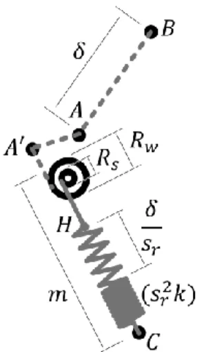
The reels can be utilized for cable driven mechanisms. By using a reel which has two different sizes (e.g., 𝑅𝑤 and 𝑅𝑠 for the wire and spring, respectively; Fig. 5), the elongation of the springs can be reduced through another shortening performance, 𝑠𝑟, as described in Eq. (8a). The reels are attached to the links. To ensure consistent performance of the pull, the torque on the reels should be kept as usual. Therefore, the spring coefficient is enlarged as the square of 𝑠𝑟, that is, 𝑘 becomes 𝑠𝑟2𝑘. With the cable driven mechanism on the basis of the reels, the mounting length of the springs is shortened as expressed in Eq. (8b). To quantify the minimum performance of 𝑠𝑟, the maximum elongation, pseudo-mounting length, and spring free length are utilized as described in Eq. (8c).
doi:10.6342/NTU201601711
19
Fig. 5 Cable driven mechanism with the reel for the spring
The benefit of using the reels is that only one reel is required for one spring;
furthermore, the reels are attached to the links, leading to higher stability of the pulley systems. Moreover, 𝑠𝑟 can be any positive number; thus, the spring coefficient will not become unmanageable. The string length considering the remaining space of the
mounting region is derived as Eq. (8d).
w r
s
s R
R (8a)
max
ava f
r
m m l
s (8b)
and
r max
ava f
s m l (8c)
𝑙𝑠 = 𝛿max+ 𝑝 + (𝑚ava− 𝑚) (8d)
doi:10.6342/NTU201601711
20
CHAPTER 4
Placing region : Spring configurations for minimizing the
placing length
4.1 Determination of pseudo-mounting length
In Eqs. (6), (7) and (8), the string length is proportional to the placing length.
Intentionally minimized the placing length helps reduce the string length. The placing length can be shortened by arranging the spring on the proximal, distal, or adjacent links. Moreover, the placing length can be further minimized by arranging the spring in the mounting region in reverse.
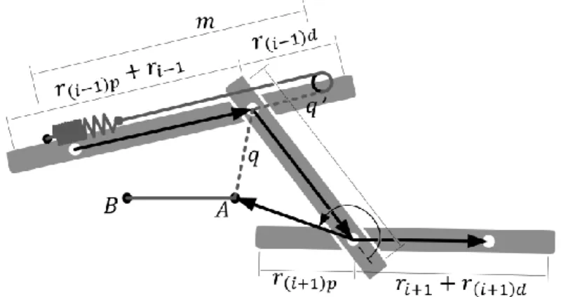
Fig. 6 Mounting length and pseudo-mounting length of springs on the adjacent links
doi:10.6342/NTU201601711
21
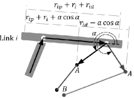
The spring configurations for the minimized placing length are determined by three parameters, namely the length of the spring attachment vectors 𝑎, 𝑏 and the pseudo- mounting length 𝑚′ of the spring configurations. The pseudo-mounting length is the maximum length available for the springs to be arranged with a minimal placing length and is theoretically limited by the link configurations, because the springs are arranged on the links. The magnitude of the pseudo-mounting length is based on the residual link length defined away from the link joints to link’s proximal or distal ends (e.g., 𝑟𝑖𝑝 and 𝑟𝑖𝑑 in Fig. 1(a)). An appropriate link configuration has a long pseudo-mounting length,
and candidates for the pseudo-mounting length can be described using Eqs. (9) for
scenarios where the springs are arranged on adjacent links, as shown in Fig. 6
𝑚𝑖−1′ = max(𝑟(𝑖−1)𝑝+ 𝑟𝑖−1, 𝑟(𝑖−1)𝑑) (9a) 𝑚𝑖+1′ = max(𝑟(𝑖+1)𝑝, 𝑟𝑖+1+ 𝑟(𝑖+1)𝑑) (9b)
The pseudo-mounting length for the springs on proximal (distal) links can be realized by giving a vertical distance from the springs to the links that shortens the placing length such that 𝑝 equals 𝑎 sin 𝛼 (𝑏 sin 𝛽). To give a vertical distance to the placing length, the springs should be arranged from the point of vertical intersection on the links. The pseudo-mounting length is therefore solved as the longest length
measured away from the point of vertical intersection.
doi:10.6342/NTU201601711
22
Fig. 7 Mounting length and pseudo-mounting length of springs on the proximal link
However, this leads to various placing length scenarios, making the equations more varied and complex because the rotation angle can be any value, as shown in Fig. 7.
Two situations of pseudo-mounting length for arranging springs on proximal and distal links is as expressed in Eqs. (10a) and (10b), respectively. If the point of vertical intersection is located on the links, the pseudo-mounting length can be determined as the longest length of the two sections separated by the point. For scenarios where the point of vertical intersection of the spring is not located on the links, the total link length can be utilized fully as the pseudo-mounting length. Depending on the rotation angle of the springs, the pseudo-mounting length with the aligned or unaligned springs can also
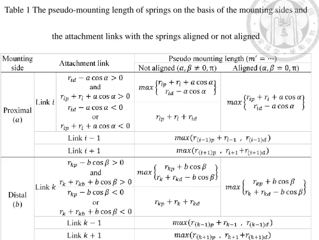
be classified. The pseudo-mounting length of the springs is listed in Table 1.
max( cos cos ) or
i ip i id ip i id
m' r r a , r a r r r (10a)
max( cos cos ) or
k kp k kd kp k kd
m' r b , r r b r r r (10b)
doi:10.6342/NTU201601711
23
Table 1 The pseudo-mounting length of springs on the basis of the mounting sides and the attachment links with the springs aligned or not aligned
4.2 Minimized placing length
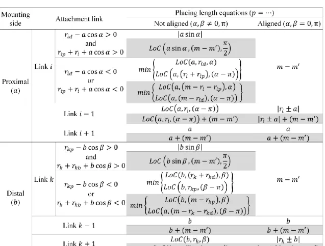
According to the spring configurations on the proximal link, distal link, or adjacent links, the minimization of the placing length on the basis of the pseudo-mounting length can be described for each configuration. Moreover, two scenarios—where the spring attachment vectors are either aligned or not aligned on the links—are discussed separately. Table 2 is a reference table for all cases of placing length equations and
classifications. Gray table cells are cases with an overextending mounting length, i.e., 𝑚 > 𝑚′, whereas the other cells are cases where 𝑚 < 𝑚′.
doi:10.6342/NTU201601711
24
A function is utilized for simplifying the law of cosines such that 𝐿𝑜𝑐(𝑎, 𝑟, 𝛼) represents √𝑎2+ 𝑟2− 2𝑎𝑟 cos 𝛼, as shown in the Table 2.
Table 2 Placing length equations of springs on the basis of the mounting sides and the attachment links
For cases where the mounting length is longer than the link length and pseudo- mounting length, the links should be extended so the springs can be arranged on the links. Multiple sets of springs can be arranged on one link. Therefore, the links may be further extended for arranging other springs.
doi:10.6342/NTU201601711
25
As an extreme case, extending the links for elongating the pseudo-mounting length
such that 𝑚′> 𝑚 always holds can be utilized. Therefore, the placing length on the proximal and distal link is a vertical distance (𝑝 = |𝑎 sin α| and |𝑏 sin 𝛽|, respectively),
which is the length measured from the point of vertical intersection to the spring
attachment point. This placing length for arranging springs on adjacent links means that the term 𝑚 − 𝑚′ can be eliminated when the springs are arranged starting from the point of vertical intersection. The equations in Table 2 can then be simplified.
doi:10.6342/NTU201601711
26
CHAPTER 5
Extension region : Routing configuration synthesis
5.1 Superposition property of articulated springs
Vectors possess superposition property. The routing configuration synthesis of the springs is a technique on the basis of the superposition property. The attachment vectors of springs are 𝒂, 𝒃 and 𝒗 defined from the aforementioned spring configures. By the superposition property of vectors, the attachment vectors are divided into 𝑛 sub vectors that 𝑛 sub loops are given herein as shown in Fig. 8, called “routing configurations” of the springs. The number of 𝑖 represents the 𝑖 sub loop of the springs, which is
composited by the sub vectors 𝒂𝒊, 𝒗𝒊 and 𝒃𝒊, where 𝑖 = 1~𝑛. The sub vectors are divided from the spring attachment vectors, i.e. 𝑛 ≥ 2. And the vectors are limited such as 0 < 𝒂𝒊 < 𝒂. The sub vectors are summed to be original magnitude as Eqs. (11) described that the superposition property of vectors is followed.
The routing configurations enable springs to be arranged with smaller sub
attachment vectors that occupies less space.
(𝒂𝟏… + 𝒂𝒊… + 𝒂𝒏) = 𝒂 (11a)
(𝒗𝟏… + 𝒗𝒊… + 𝒗𝐧) = 𝒗 (11b)
(𝒃𝟏… + 𝒃𝒊… + 𝒃𝒏) = 𝒃 (11c)
doi:10.6342/NTU201601711
27
Fig. 8 The illustrated model for the superposition property of spring attachment vectors
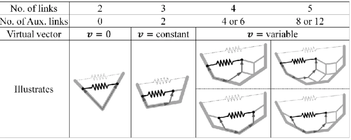
The superposition in virtual link vector can be realized by the utilization of
auxiliary links as Table 3 presents. Parallelogram linkages provide a copying property of the vectors to form the sub loops of the springs. Because the number of auxiliary links increases with the more joints that a spring spans over, the number of spanned links less than 4 is suggested. Moreover, the minimum auxiliary links are utilized for each spring configurations so the springs are arranged neither on proximal link nor distal link.
Table 3 The number and configurations of auxiliary links for virtual link
doi:10.6342/NTU201601711
28
To reduce the variables of the vector equations, scale ratio of the sub vectors w.r.t.
the attachment vectors are used such that 𝑁𝑎𝑖 = 𝑎𝑎𝑖, 𝑁𝑣𝑖 = 𝑣𝑣𝑖 and 𝑁𝑏𝑖 =𝑏𝑏𝑖, so
normalized vectors can be shown, i.e. 0 < 𝑁𝑎𝑖 < 1. With the normalization of vectors, following by the superposition property of vectors, the initial constraints of the sub
vectors in Eqs. (11) can be described as Eqs. (12) shown:
∑𝑛𝑖=1𝑁𝑎𝑖 = 1 (12a)
∑𝑛𝑖=1𝑁𝑣𝑖 = 1 (12b)
∑𝑛𝑖=1𝑁𝑏𝑖 = 1 (12c)
5.2 Routing configuration synthesis on the basis of equivalent articulated springs
While designing the routing configurations of the articular springs, to maintain the consistent spring capability in joint torques as expressed in Eqs. (3), a concept of conservation law is followed that the summation of the spring capability of sub-loops are supposed to be as usual as the original spring configuration described in Eqs. (13),
where the spring coefficients of sub-loops are normalized by the origin springs, i.e.
𝑁𝑘𝑖 =𝑘𝑘𝑖> 0, so the variables can be further reduced such as Eqs. (12), and the routing
configuration synthesis will be more general for different design cases.
∑𝑛𝑖=1𝑁𝑘𝑖𝑁𝑎𝑖𝑁𝑏𝑖 = 1 (13a)
∑𝑛𝑖=1𝑁𝑘𝑖𝑁𝑎𝑖𝑁𝑣𝑖 = 1 (13b)
∑𝑛𝑖=1𝑁𝑘𝑖𝑁𝑏𝑖𝑁𝑣𝑖 = 1 (13c)
doi:10.6342/NTU201601711
29
The physical meaning of Eqs. (13) is that a spring can be substituted by the other springs with their spring capability in joint torque are kept consistent, where the springs are call equivalent springs. To find the spring coefficients of the equivalent springs, the value of sub attachment vectors can be served as known parameters to solve the spring coefficients such that the 𝑁𝑘1, 𝑁𝑘2 … and 𝑁𝑘𝑛 are variables to be determined.
Simplifications can be utilized, for instance, the same spring capability in each sub
loop, 𝑁𝑘1𝑁𝑎1𝑁𝑏1 = 𝑁𝑘𝑖𝑁𝑎𝑖𝑁𝑏𝑖 can be assumed, or using the same spring coefficients, 𝑁𝑘𝑖 = 𝑐𝑜𝑛𝑠𝑡𝑎𝑛𝑡 to derive available solutions. In order to compressively discuss the
general solution, no simplifications will be applied in the derivation, and the derivation of the routing configuration synthesis with two steps, 𝑛 = 2, is introduced in this paper as Fig. 9 describes.
Fig. 9 The routing configuration synthesis of the springs by two steps
doi:10.6342/NTU201601711
30
Two steps of the routing configurations are assumed, and 𝑁𝑘1 and 𝑁𝑘2 are the spring coefficients of the two equivalent springs to be solved shown in Eqs. (14). The simultaneous equations can be realized by graphical method that the coordinates of 𝑁𝑘1
and 𝑁𝑘2 are used and 𝑁𝑎1𝑁𝑏1 or 𝑁𝑎2𝑁𝑏2, for instance, are therefore the coefficient of 𝑁𝑘1 and 𝑁𝑘2 respectively.
𝑁𝑘1𝑁𝑎1𝑁𝑏1+ 𝑁𝑘2𝑁𝑎2𝑁𝑏2=1 (14a)
𝑁𝑘1𝑁𝑎1𝑁𝑣1+ 𝑁𝑘2𝑁𝑎2𝑁𝑣2=1 (14b)
𝑁𝑘1𝑁𝑏1𝑁𝑣1+ 𝑁𝑘2𝑁𝑏2𝑁𝑣2=1 (14c)
The sub vectors are realized as the intercept of each equation. As Fig. 10(a) presents, a dependent solution of Eqs. (14) can be solved if the three lines are collinear to each other. The intercepts are equal as Eq. (15a) shows, and the relationship between each sub vector can be derived in Eq. (15b) while the spring coefficients can then be
solved as Eq. (15c). A linear dependence solution of the equivalent springs exists.
⇒ 𝑁𝑎1𝑁𝑏1 = 𝑁𝑎1𝑁𝑣1= 𝑁𝑏1𝑁𝑣1 (15a)
⇒ 𝑁𝑎1 = 𝑁𝑏1 = 𝑁𝑣1 (15b)
⇒ 𝑁𝑘1 = 𝑁1
𝑎12 −𝑁𝑁𝑎22
𝑎12 𝑁𝑘2 (15c)
On the other hand, a unique solution of the spring coefficients of Eqs. (14) can be solved once these three lines intersect each other. The situation can be distinguished into two cases: an intersection of the lines with and without overlapping shown in Fig. 10(b).
doi:10.6342/NTU201601711
31
For the case of the lines with overlapping, because two lines overlap to each other, coefficients are same and equations are simplified. By the simplified two equations, an intercept of the two lines can be found and the value of the spring coefficients can be calculated as a function inversely proportional to the parameters. That is to say, if the Eqs. (14a) and (14b) overlap to each other, a solution of the spring coefficient can be found in the first part of Eqs. (16). If the Eqs. (14a) and (14c) are chosen, the solution will be the second part of Eqs. (16), while the third part is derived for the Eqs. (14b) and
(14c).
⇒ 𝑁𝑎1𝑁𝑏1= 𝑁𝑎1𝑁𝑣1 or 𝑁𝑎1𝑁𝑏1 = 𝑁𝑏1𝑁𝑣1 or 𝑁𝑎1𝑁𝑣1= 𝑁𝑏1𝑁𝑣1 (16a)
⇒ 𝑁𝑎1 ≠ 𝑁𝑏1 = 𝑁𝑣1 or 𝑁𝑏1 ≠ 𝑁𝑎1 = 𝑁𝑣1 or 𝑁𝑣1≠ 𝑁𝑎1 = 𝑁𝑏1 (16b)
⇒ 𝑁𝑘1 =𝑁1
𝑏1= 𝑁1
𝑣1 or 𝑁𝑘1 = 𝑁1
𝑎1= 𝑁1
𝑣1 or 𝑁𝑘1 =𝑁1
𝑎1 = 𝑁1
𝑏1 (16c)
For the case of the lines without overlapping, one intercept of the three lines can be given as shown in Fig. 10(b). However, considering the constraints of the routing
configurations that the superposition property of the vectors should be followed, the unique solution that none of these three lines are parallel to each other are unable to be derived. A contradiction solution will be given such as the lines are overlapping if none overlapping case are assumed. These solutions show that the form 𝑁𝑎1 ≠ 𝑁𝑣1≠ 𝑁𝑏1 is invalid and not available for the routing configurations as a result.
doi:10.6342/NTU201601711
32
(a) Collinear case (b) An intersection with and without overlapping Fig. 10 The possible solutions of spring configurations on the basis of graphical method
With the previous derivations, the general solutions of the routing configurations can be found. Two cases of routing configurations show that the number of diverging parameters in the sub vectors 𝑁𝑎, 𝑁𝑣, 𝑁𝑏 should be 0 or 1. The first situation is that the sub vectors are equal to each other, and are resulted in a geometric similarity such as each sub loop is a smaller version of original loop.
Another situation is that one sub vector owns different value with respect to the
other two vectors, so called diverging parameters. The diverging parameter can locate in 𝑁𝑎, 𝑁𝑣 and 𝑁𝑏. If the diverging parameter locates in 𝑁𝑣, two ways to reach the
situation of scaled 𝑁𝑣 can be used. One is by scaling it’s all compositions such that a
geometric similarity is utilized for each sub vector, i.e. (𝑁𝑟(𝑖+1)… = 𝑁𝑟(𝑗)… = 𝑁𝑟(𝑘−1)) = 𝑁𝑣. However, this gives a variable length of the vector 𝑁𝑣 that makes it
impractical for applications since the length of the auxiliary links are constant but the length of the virtual link is variable. So another way to reach the situation of scaled 𝑁𝑣
doi:10.6342/NTU201601711
33
by just scaling one arbitrary composition of the virtual link is introduced. Only one link is chosen as a substitute of the diverging. In this way, the auxiliary links can be actually applied on the manipulators rather than be applied on the variable length of the virtual link. Two criteria for briefly describing the routing configuration synthesis are
concluded and established in Table 4.
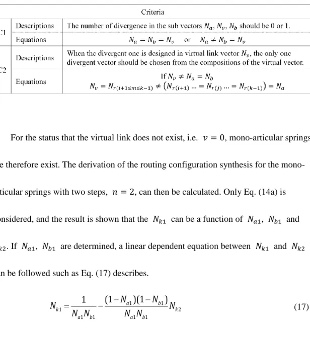
Table 4 Criteria of the routing configuration synthesis for articulated manipulator
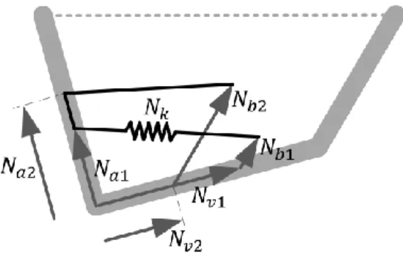
For the status that the virtual link does not exist, i.e. 𝑣 = 0, mono-articular springs are therefore exist. The derivation of the routing configuration synthesis for the mono- articular springs with two steps, 𝑛 = 2, can then be calculated. Only Eq. (14a) is
considered, and the result is shown that the 𝑁𝑘1 can be a function of 𝑁𝑎1, 𝑁𝑏1 and 𝑁𝑘2. If 𝑁𝑎1, 𝑁𝑏1 are determined, a linear dependent equation between 𝑁𝑘1 and 𝑁𝑘2
can be followed such as Eq. (17) describes.
1 1
1 2
1 1 1 1
(1 )(1 )
1 a b
k k
a b a b
N N
N N
N N N N
(17)
doi:10.6342/NTU201601711
34
5.3 Routing configuration synthesis of articulated springs by wire winding
With the aforementioned routing configurations, the springs can be substituted by two or more equivalent springs that performs consistent spring torque to the
manipulator. However the utilization of multiple springs increases the difficulty of using routing configurations because the more springs used, the more interference may occur.
One solution to make it easier to arranging springs is by the technique of “wire winding”. The wire winding is that the redundant springs are removed and only one
equivalent sole spring is utilized for the routing configurations as shown in Fig. 11. The sub loops are connected. On this condition, the spring elongations of each sub loop are shared to each other and the spring coefficient are unique, that is, 𝑁𝑘1= 𝑁𝑘2 = 𝑁𝑘 if the two steps routing configuration are assumed. Therefore, elastic elements with similar characteristics can be utilized, e.g. a rubber band or an elastic Band.
Fig. 11 The routing configuration synthesis of the springs with the wire winding technique by an equivalent sole spring.
doi:10.6342/NTU201601711
35
Because the spring elongations are summed, by distributive law, two separated elongations should have the same term for combination. A scale parameter of the elongation is set as 𝑠𝑐 so Eq. (18a) can be realized as Eqs. (18b) and (18c) for the wire winding.
𝛿 = ∑2𝑖=1√(𝒗𝒊+ 𝒃𝒊− 𝒂𝒊) ∙ (𝒗𝒊+ 𝒃𝒊− 𝒂𝒊) (18a) 𝛿 = (1 + 𝑠𝑐)√(𝒗𝟏+ 𝒃𝟏− 𝒂𝟏) ∙ (𝒗𝟏+ 𝒃𝟏− 𝒂𝟏) (18b) 𝛿 = (1 + 𝑠𝑐)√𝑣12+ 𝑏12+ 𝑎12+ 2(𝑣1𝑏1𝑐𝑜𝑠𝜃𝑣𝑏− 𝑣1𝑎1𝑐𝑜𝑠𝜃𝑎𝑣− 𝑎1𝑏1𝑐𝑜𝑠𝜃𝑎𝑏) (18c)
For multi-articular springs, because each joint angle is the independent variable of the springs, one way to make the spring elongation reasonable is by ensuring the ratio of each coefficient to be a constant as described in Eq. (19a). The normalization of sub vectors are then used and the results of the routing configurations with wire winding are
shown in Eq. (19b).
2 2 2
2 2 2 2 2 2 2 2 2 2
2 2 2
1 1 1 1 1 1 1 1 1
2 2 2
2 2 2 c
v b a v b v a a b s v b a v b v a a b
(19a)
1
1 1 1
1
, ? 1 a
a v b c
a
N N N s N
N
(19b)
The wire winding technique for the routing configurations give a symbiosis relationship to the springs since the elongation are shared. The symbiosis relationship can be realized by the extra elongation given from other sub loops as Eqs. (20a) to (20c) shown. So, the spring coefficient of the wire winding in multi-articular springs is
doi:10.6342/NTU201601711
36
therefore solved as Eq. (20d) on the basis of Eqs. (19), which is further reduced with
respect to the routing configurations without wire winding since 𝑠𝑐 > 0.
(1 + 𝑠𝑐)𝑁𝑘𝑁𝑎1𝑁𝑏1+ (1 +𝑠1
𝑐) 𝑁𝑘𝑁𝑎2𝑁𝑏2= 1 (20a) (1 + 𝑠𝑐)𝑁𝑘𝑁𝑎1𝑁𝑣1+ (1 +𝑠1
𝑐) 𝑁𝑘𝑁𝑎2𝑁𝑣2 = 1 (20b) (1 + 𝑠𝑐)𝑁𝑘𝑁𝑏1𝑁𝑣1+ (1 +𝑠1
𝑐) 𝑁𝑘𝑁𝑏2𝑁𝑣2= 1 (20c)
1 1 2 21
1 1 1
k
c a b a b
c
N
s N N N N
s
(20d)
If the virtual link does not exist, i.e. 𝑣 = 0, mono-articular springs are therefore exist. The derivation of the routing configurations with the wire winding in mono- articular spring by two steps, 𝑛 = 2, is shown in Eq. (21a) and calculated in Eq. (21b).
However, the term, 𝑏𝑎, is waited to be defined. A shape parameter of the attachment vectors are therefore utilized for the term and notified as 𝑠ℎ so Eq. (21c) can be derived and the results can be shown in Eq. (21d). Two cases of the routing
configurations with the wire winding for mono-articular springs are presented. The wire winding technique can be applied once the shape parameter follows Eq. (21d). Or the shape parameter can be any once two sub vectors are equal to each other. With Eqs.
(21), the spring coefficient of mono-articular springs can be therefore solved as Eqs.
(20a) and (20d).
doi:10.6342/NTU201601711
37
2 2
2 2 2 2 2
2 2
1 1 1 1
2
2 c
b a a b s b a a b
(21a)
2 2 2
1 2 1 1 1
2 2 2 1 1
1 2 1
1 a 1 b 1 a 1 b
a b
a b
N ba N N N
b N N
N N
a
(21b)
and
(𝑁𝑎1− 𝑁𝑏1)((𝑁𝑎12 − 𝑁𝑎1)𝑠ℎ2− (𝑁𝑏12 − 𝑁𝑏1)) = 0 (21c)
{𝑁𝑎1, 𝑁𝑏1= any, if 𝑠ℎ = √𝑁𝑁𝑎12 −𝑁𝑎1
𝑏12 −𝑁𝑏1 is satisfied 𝑠ℎ = any, if 𝑁𝑎1 = 𝑁𝑏1
(21d)
The wire winding for multi-articular springs can be realized by the geometric
similarity, which means that the two sub loops have the similar shape. The difference in size can be represented by the elongation as a scale parameter 𝑠𝑐, which is one edge of
the sub loops. While the wire winding for mono-articular springs are not, and can be diversity.
5.4 Classifications and types of routing configurations
The routing configurations with and without wire winding are derived. The routing configurations can be designed with one or no diverging parameter in it. Moreover, classifications and types of the routing configurations can be presented on the basis of the correlation between attachment vectors. A simplified model for temporarily deriving the classifications and types of the routing configurations is shown in Fig. 12. A multi- articular spring can be distinguished into multi-part and mono-part by shifting the
doi:10.6342/NTU201601711