Study on Photovoltaic Grid-connected Inverter Control System
Hui Zhang, Lin Shan, Jing Ren, Baodan Cheng
Xi’an University of Technology 710048, Xi’an, Shaanxi, China
[email protected]
Hongwei Zhang
Xi’an Yongdian Electric Co.Ltd 710015, Xi’an, Shaanxi, China
[email protected]
Abstract--The grid-connected photovoltaic generation system is the most important one in the field of photovoltaic application.
In this paper, a model of photovoltaic has been constructed based on the main circuit of single phase grid-connected generation system using MATLAB/simulink to program it. The double closed loop control structure is adopted and forward- feed compensation method is employed to the system. It made the grid-connected current track the presetting sinusoidal reference signal in real time. The analytical and simulated results show that the grid-connected current waveform of the system is improved effectively and a faster dynamic response is obtained and forward-feed compensation control depress the grid disturbance.
Index Terms—photovoltaic grid-connected generation system; forward-feed compensation
I. I
NTRODUCTIONEnergy crisis and environmental pollution make people pay much attention to renewable energy. Specifically, solar energy is considered to be one of the most useful natural energy sources because it is free, abundant, pollution-free, and most widely distributed and photovoltaic (PV) grid-connected generation system is the trend of solar energy application. To achieve high efficiency of power converter is the key technologies of the power converter interface for the grid- connected generation system. In PV grid-connected system, a PWM inverter used for a grid-connected scheme is controlled in order to produce an output current in phase with the utility voltage thus to obtain a unity Power Factor (PF).
As shown in Fig.1 and Fig.2, PV grid-connected generation system can be divided into single-stage system and two-stage system according to the main circuit’s topology [1][2].
Fig. 1 Single-stage system
Single-stage system is shown in Fig.1 includes dc/ac, the maximum power point tracking (MPPT) and inverter function is achieved only by this stage, therefore, the realization of control algorithm is complex relatively.
Fig .2 shows a two-stage system which is composed of two parts, dc/dc and dc/ac. The solar cell array converts the solar energy from the light energy into dc power, and the dc power serves the input of the grid-connected inverter.
Fig. 2
Two-stage
systemII. M
AINC
IRCUITC
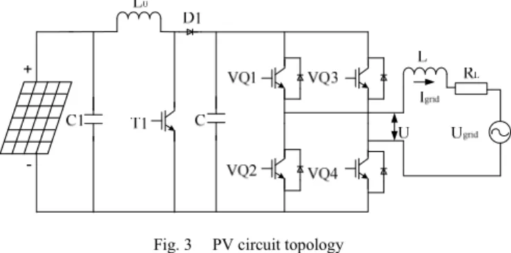
ONFIGURATION A. The Principle of SystemIn this paper, the topology of two-stage system is mainly considered. The configuration of the grid-connected power system is shown in Fig.3.
Fig. 3 PV circuit topology 1
The whole system is composed of the PV array, the dc/dc boost converter, the Single-phase full-bridge inverter. The boost circuit is used not only to lift the dc-link voltage of the inverter but also to realize MPPT for the PV array output.
Single-phase full-bridge inverter which includes four power semiconductors and an output inductor , is regarded as the dc/ac power conversion circuit to meet the requirement of grid output current in phase with the utility voltage for obtaining a unity PF.
The authors gratefully acknowledge the financial support of the National Natural Science Foundation of China (50977078) the Provincial Natural Science Foundation of Shaanxi (2009JM7001) the Provincial Education Department Foundation of Shaanxi (09JK676) the Key Technology R&D Program of Xi’an (CXY08005)
PEDS2009
210
B. Maximum Power Point Tracking
Fig.4 (a) and (b) shows the P/U characteristic curves of solar cell array under different temperature and irradiance level. It can be seen that PV modules have nonlinear voltage- power characteristics, and there is only one unique operating point for a PV arrays. In order to use of effectively, it needs to be operated the MPP [3]. MPPT is an self-seeking- optimization processes, in specific situation, measured values of the PV generator's power is compared with those stored in the controlling system, abandoned smaller and remained bigger value until achieving the maximum power. In this paper, duty cycle of the boost circuit is adjusted to track power in this system.
0 5 10 15 20 25
0 10 20 30 40 50 60 70 80 90
U/V
P/W
25 50 75
(a)P/U curves under different temperature level
0 5 10 15 20 25
0 10 20 30 40 50 60 70 80 90
U/V
P/W
1kW m/ 2
0.8kW m/ 2
0.6kW m/ 2
(b) P/U curves under different irradiance level Fig. 4 Characteristics of PV modules
III. C
ONTROLS
TRATEGYThere are two ways of output control strategy of PV grid- connected generation system, current control and voltage control. If voltage control is applied to controlling the output of inverter, the system is paralleled with two voltage source.
It is not easy to reach the performance indexes in this case.
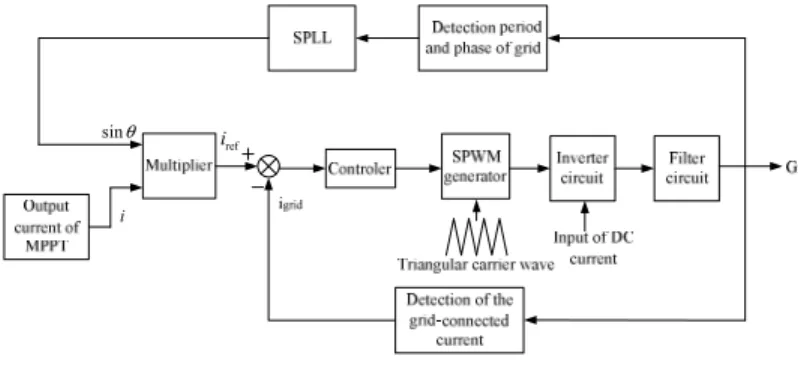
For current control, grid is believed to be a voltage source with an infinite capacity controlling the output current of inverter and tracking the phase of the grid- voltage to attain PV grid-connected[2][4].The PWM algorithm of grid- connected inverter was based on double closed loop current control as show in Fig.5.
The loop of voltage lies in outer loop and the loop of current is inner loop. The outer loop functions to stabilize the
DC voltage of photovoltaic array. The aim of inner loop is to track the given current signal. By regulating the parameters of current loop, tracking speed can be advanced and tracking error can be reduced. This framework include software phase-locked-loop (SPLL) to achieve the output current of the power inverter is desired to be sinusoidal and in phase with the utility voltage.
i sinθ
iref
Fig. 5 Control scheme for system
Fig.3 illustrates the PWM inverter framework including four power semiconductors and an output inductor. R
Lis the equivalent series resistor of the output inductor; I
gridis the output current of the full-bridge inverter; U is the output of the inverter and U
gridis the grid voltage.
The mathematic model of gird-side converter can be given:
grid grid
grid L
L d I U U I R
⋅
dt= − − (1) Described in complex field form:
grid 3 grid
( ) 1 ( ( ) ( )) ( )( ( ) ( ))
grid
L
s U s U s G s U s U s
I =Ls R − = −
+
(2)
Where
G3( )
sis transfer function of the filter .
3
( ) 1
L
G s
= Ls R
+ (3) The transfer converter can be defined G s
2( ) and described as follow:
2
( )
1
PWM PWM
G s k T s
= + (4)
Where k
PWMis the amplifier coefficient of the converter;
T
PWMis time constant of the converter.
To reduce the steady-state error and increase system stability, a PI type controller is used in the current loop. It is shown in Fig.6 that is mode control of grid-side converter block diagram. PI controller equations as follow:
PEDS2009
211
1
( ) s K
PK
IG s
= + (5)
Iref Igrid
− +
1s
G( ) G( )2 s G( )3s
Fig. 6 PI mode control of grid-side converter block diagram
In order to reduce disadvantageous of perturbation of grid voltage, forward-feed compensation output is added to this system. This method is not only unchanged the characteristics of control system, but also improved stability.
The I
ref= 0
,an effect of disturbance of the grid voltage is described as follow:
3
1 2 3
( ) ( ) ( )
1 ( ) ( ) ( )
grid grid
I s G s U s
G s G s G s
= − + (6)
In generally, it is hoped that system output is 0 under the operation of any form of disturbance. So, forward-feed compensation output is added to as shown in Fig.7 and it can be conclude an equation:
3 4 2
grid
1 2 3
( )( ( ) ( ) 1)
( ) ( )
1 ( ) ( ) ( ) G s G s G s
E s U s
G s G s G s
= −
+ (7)
Iref Igrid
− +
1s
G( ) G( )2s G( )3s
4s G( )
Fig. 7 Add forward-feed compensation mode control of grid-side converter block diagram
4 2
( ) 1 G s ( )
= G s
and Igrid =0, the impact of disturbance is eliminated.
IV. S
IMULATIONR
ESULTSThe simulation model of the sing-phase grid-connected photovoltaic system was established in Matlab/simulink.
Some circuit parameters are listed as follow:
DC voltage U=48V;
grid voltage U
grid=22V;
grid frequency f=50Hz;
filter inductor L=0.003mH.
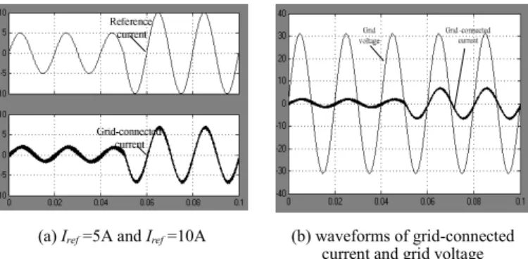
Given current I
refchanges suddenly from 5A to 10A and forward-feed compensation output is not added, the simulation waveforms are depicted in Fig.8(a) and (b).
(a) Iref=5A and Iref=10A (b) waveforms of grid-connected current and grid voltage Fig. 8 Simulation waveform without forward-feed compensation
Given current I
refchanges suddenly from 5A to 10A and forward-feed compensation output is added, the simulation waveforms are shown in Fig.9 (a) and (b)
(a) Iref=5A and Iref=10A (b) waveforms of grid-connected current and grid voltage Fig. 9 Simulation waveform with forward-feed compensation
From the Fig.8 and Fig.9, it can be seen that when I
ref=5A, THD of output current is about 7.5%; when I
ref=10A, THD=2.9% and output current can not follow up
the input current precision. Meanwhile, all conditions of simulation is same as before, when adding forward-feed compensation, reference current I
refchanged from 5A to 10A, THD of output current is diminished from 3.8% to 1.8%
and the output current of converter makes the grid-connected current track the magnitude of reference current exactly.
R
EFERENCES[1] Carlos Meza, Domingo Biel, “Considerations on the Control Design of DC-link Based Inverters in Grid-Connected Photovoltaic Systems,”2006.
[2] Zhao Wei, Yu Shijie, “Research on Grid-Connected Photovoltaic System,”[D], Energy Research Institute,Hefei University of Technologyy, 2003.
[3] Hardik P.Desai , H.K.Patel, “Maximum Power Point Algorithm in PVGeneration:An Overview,” PEDS, 2007.
[4] Wang Fei, Yu Shijie, Su Jianhui ,Shen Yuliang, “Research on Photovoltaic Grid-Connected Power System,” Transaction of China electrotechnical society, No.5, vol. 20, pp.72–74, May 2005.