The Finite Elements Analysis on Magnetic Field of Controllable Saturated Reactor
Wang Ziqiang, Yin Zhongdong, Yang Po, Li Ke
Key Laboratory of Power System Protection and Dynamic Security Monitoring and Control of Ministry of Education North China Electric Power University
Beijing, China
E-mail: [email protected]
Abstract—In the power system, the controllable reactor can be used as reactive power compensation device to limit over-voltage operation, reduce no-load or light load loss and improve transmission capacity. It is with characters of simple structure, easy maintaining, low cost and high stability, etc. The magnetic field is closely related to the reactor performance. In this paper, aiming at a controllable saturated reactor prototype, using the finite elements method, the magnetic field is studied. Then, the precise 2-D prototype field-circuit coupling model is established based on the magnetic field analysis and the finite element analysis software - ANSYS. Using this model, the magnetic field and working currents concrete values under the condition that AC and DC excitations co-exist within the core are calculated.
The analysis results indicate that finite element analysis theory can effectively analyze the magnetic field of the reactor.
Keywords-magnetic field; controllable saturated reactor; finite elements theory
I. I NTRODUCTION
Finite element method (FEM) is a numerical method which is used to approximately solve the general problem of continuous fields. In 1943, the basic idea of the finite element theory was proposed by R.Courant for the first time, and this theory has been continuously improved by scholars, with a rapid progress. Finite element theory which is originated in the structural analysis theory has been gradually used in the Electromagnetic field analysis after its theory and formula are improved and promoted [1].
The finite element analysis software ANSYS can be used to conduct electromagnetic calculation, solve the problem on the distribution of magnetic field in a particular device or a certain component. Maxwell equations are the starting point of the electromagnetic analysis. The unknown value (DOF) that mainly calculated in the finite element method is magnetic potential or electric potential. Other issues, such as magnetic flux density, current density, energy, force, loss, inductance and capacitance can be derived from these unknown values [2].
Saturated reactor is a kind of nonlinear circuit with iron core, DC and AC windings. It controls saturation degree of the iron core by using of the DC excitation, thus changes the reactance of the AC winding. The field-circuit coupling model of the saturated reactor refers to the model of taking account of the external circuit and the magnetic field within the iron core.
II. C ORE S TRUCTURE AND M AGNETIC F IELD A NALYSES A. Core Structure of Saturated Reactor
The magnetic properties of iron core are related to ferromagnetic materials, iron core structure and manufacturing process. Therefore, suitable magnetic materials should be chosen. Magnetic materials used now are Fe-Ni alloy and cold- rolled silicon sheet. The eddy current should be taken into account when choosing the thickness of the iron core material in order to reduce the iron loss and limit the temperature rise.
Comprehensive consideration suggests that 0.3-0.35mm is the optimal choice considering the fact that the thinner the magnetic material, the lower some properties will be. The reactor prototype studied in this paper uses cold-rolled non- oriented silicon steel sheet, with a thickness of 0.35mm.
Besides, in order to make full use of the magnetic properties of iron core, it is necessary to choose a reasonable structure and size ratio. Non-uniform magnetization occurs, air gap exists in the magnetic circuit, or individual magnetization direction of the magnetic circuit is different from the easiest magnetization direction of the material can affect the iron core’s magnetic properties. In the choice of core structure and its geometry size, the inherent magnetic properties should be made full use of. And at the same time, smallest geometry size and lightest weight should be pursued in the premise of technical requirements. Finally, easy to manufacture and economic cost should be considered also. Above all, the core structure of the saturated reactor and the external circuit are as follows:
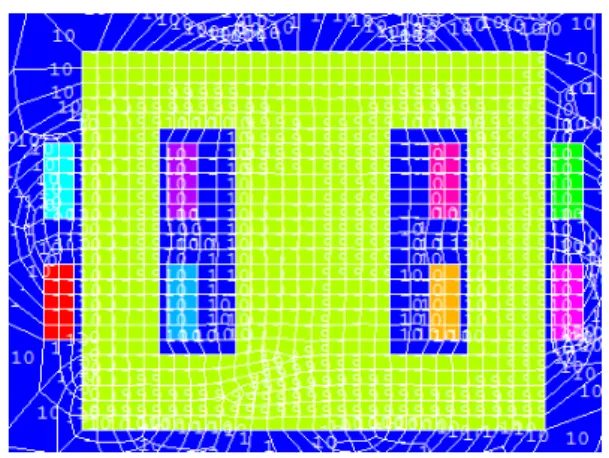
Figure 1. Core structure and circuit.
In Fig.1, the primary core of the reactor is divided into identical two parts which have the same cross-section area.
Furthermore, the cross-section area of the middle yoke is twice times as much as a side core. Four windings, with the same turns of N, are symmetrically winded on the two side core columns respectively. At the same time, the upper and lower windings distributed on different columns are cross connected to form two circuits which are in parallel connection. Then they are all connected to the network source U. Besides, the two nodes in the middle of the branches are connected to DC control source E.
When the saturated reactor works, the control actions are performed by DC excitation, and therefore the DC control winding is also called controlling winding. At the same time, the AC winding (work winding) is connected with the load.
When the DC excitation current doesn’t exist, the inductance of the AC winding is the largest and the current is the smallest.
This state is equivalent to the no-load transformer. When DC excitation maintains unchanged, the DC and AC components of the magnetic induction coexist in the iron core. Because of the additive effect of AC and DC excitation, the core will work on the saturation state of magnetic property. Therefore, AC magnetic field intensity increases and the core’s equivalent permeability decreases at the same time [3]. The more saturated the iron core, the smaller the permeability and the reactance of non-linear reactor will be. When the voltage of the power source keeps invariant, the reactance will keep constant too. And in this case, the reactor is uncontrollable.
B. Magnetic Field Analysis of The Core Magnetic Field The finite element calculation method, used in the magnetic field of saturated reactor iron core, is a extremum problem that converts boundary value problems on differential equations of magnetic field into equivalent energy functional. Then field domain is discretized into finite units, and in each unit the unknown functions are expressed by interpolating functions with unknown coefficients. By substituting the interpolating function into the integral formula of energy functional, the functional is discretized into ordinary multivariate function.
According to the principle of extremum problems on multivariate function, partial derivations of each variable in the energy function are solved. Through making the results equal to zero, linear or non-linear equations will be got [4].
The saturated reactor works under the frequency of 50Hz, so the magnetic field is the low frequency steady alternating magnetic field. All of the points in each unit have the same magnetic field intensity. After the displacement currents are neglected, Maxwell Equations of the reactor can be expressed as follows:
E B t
∇× = − ∂
∂ (1)
H J
∇× = (2) 0
∇ ⋅ = (3) B Where, ∇× and ∇⋅ is respectively curl operator and divergence operator; H is magnetic field intensity vector; J is
magnetic flux density. The relationships among these field quantities are as follows: D = ε E , B = μ H , J = σ E . Where, D, ε , μ and δ is respectively electric displacement vector, dielectric constant, permeability and conductivity.In order to reduce the number of the unknown quantities, magnetic vector potential A and electric scalar potential ϕ are introduced.
B = ∇× (4) A Substituting the equation (4) into (2), differential equation of the magnetic vector potential can be expressed as follows:
1 A J
∇× ∇× = (5) μ Integrating the first and the second class boundary conditions, the boundary value problem represented by magnetic vector potential A can be expressed as follows:
1 0
2
1
:
: 1 0
A J
A A A n μ
μ
⎧ ⎛ ⎞
∇× ∇× =
⎪ ⎜ ⎟
⎝ ⎠
⎪⎪ Γ =
⎨ ⎪
⎪Γ ∇× × =
⎪⎩
(6)
The variational problems equivalent to formula(5)can be expressed as follows:
( )
1 0
: min 1
2 :
I A H Bd A Jd
A A
Ω Ω
⎧ Ω = ⋅ Ω − ⋅ Ω
⎪ ⎨
⎪ Γ =
⎩
∫ ∫ (7)
The magnetic field is discretized into finite space units, by which the nodes are formed. And the solving function A(x, y, z) can be expressed by basic function g and node function value i
A as follows: i
1
ˆ N
i i i
A A g
=
= ∑ (8) Where, N is the total number of nodes in the solved region.
If the formula (7) is unfolded under rectangular coordinates, the result can be expressed as follows:
( ) ( )
( )
2 2 2
1 2
x y z
x x y y z z
I A B B B dxdydz
A J A J A J dxdydz μ
Ω
Ω
= + +
− + +
∫
∫ (9)
Where, the discrete forms of B 、 x B y and B z are:
1 1
1 1
ˆ ˆ ˆ
n n
i i
x zi yi
i i
n n
i i
y xi zi
i i
n n
i i
g g
B A A
y z
g g
B A A
z x
g g
B A A
= =
= =
∂ ∂
⎧ = −
⎪ ∂ ∂
⎪ ⎪ = ∂ − ∂
⎨ ∂ ∂
⎪ ⎪ = ∂ − ∂
⎪
∑ ∑
∑ ∑
∑ ∑
(10)
Substituting discrete equations (8) and (10) of ˆA and ˆB into equation (9), the variational problem of I A x y z ( ( , , ) ) can
be transformed into the extremum problem of multivariate function.
( )
0 = , , ; =1, 2, ,
wi
I w x y z i N
∂ = A
∂ " (11)
III. F IELD -C IRCUIT C OUPLING M ODEL OF S ATURATED R EACTOR
A. The Field-Circuit Coupling Mathematical Model
Using finite element method and field-circuit coupling method, electromagnetic field of the saturated reactor is analyzed. The excitation in this model is voltage source, and the relation equations of the current in conductor, induced electromotive force and external excitation are established in order to find out the distribution of current and voltage.
The winding circuit equation of the reactor field-circuit coupling model can be described as follows [5]:
[ ] [ ] [ ][ ] [ ] [ ] U = E − R i − L ∂ ∂ t i (12) Where, [ ] U , [ ] E , [ ] R and [ ] L is the node voltage, induced electromotive force, resistance and inductance of the winding correspondingly.
The induced electromotive force of the winding can be expressed like this.
( )
( )
d n BdS S
e d
dt dt
d n Adl A
n dl
dt t
ψ
Γ
= − = −
= − = − ∂
∂
∫
∫ (13) If the length of each turn is l turn , and N0 subdivision elements exist in the subdivision region of the winding, the average induction electromotive force of the winding can be expressed as follows:
[ ] [ ]
0 1
1
1
=
S S
N
i i e
i
n A
E edS dl dS
S S t
nl A
A g C
S t ω t
Γ
=