WM5-4
3:OOProceedings of the 1999 IEEE
International Conference on Control Applications
Kohala Coast-ls!and of Hawai'i, Hawai'i, USA -August 22-27, 1999
Adaptive Nonlinear Control of Repulsive Maglev Suspension
Systems
Chao-Ming Huang Min-Shin Chen lia-Yush Yen
Ph.D. Candidate Professor Professor
Department of Mechanical Engineering. National Taiwan University, Taipei, Taiwan 10617. R.O.C. Ab
s
t r a e tMagnetic levitation systems have recently become the focus of many research interests not only because they are most suitable for high precision engineering applications but also due to the fact that they represent a difficult challenge to control engineers. As a result, most previous shldies have focused on the control stabilization problem. In this paper, we address the issue of performance with respect to uncertainty in order to achieve a desired rigidity. The proposed controller is an adaptive hackstepping controller. The adaptive hackstepping controller provides system stability under model uncertainty, and achieves the desired servo performance. The experiments show that the proposed control achieves a superior behavior than other control.
1. Introduction
With the development of the industry technology, numerous motion control devices and advanced fabrication equipment's have been designed to meet the high-precision positioning demand. Due to the non-contact characteristics, the suspension system based on maglev technology plays an important role in the positioning system design. A. maglev system can be classified, based on the levitation forces, as an attractive system or a repulsive system. Most of the maglev systems discussed in the literature are attractive systems, where attractive forces are applied between the moving carriage and fixed guide rails [I]-[5]. On the other hand, the repulsive maglev systems use repulsive forces to push the moving carriage above the fixed guide rails [I], [6], [ 7 ] ,
[XI.
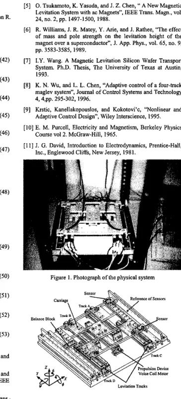
Maglev technology can also be classified into the passive maglev which uses two permanent magnets with the same poles facing each other to generate repulsive force, and the active maglev which uses a permanent magnet levitated above a dc electromagnet. The experimental device used in this paper (Figure 1, 2) is a repulsive maglev suspension system; however, it is neither active nor passive. Our design is to compound both active and passive maglev technique designs.When using active maglev only, one must apply current to dc electromagnets all the time to make camage fly, but this will overheat the levitation coils of electromagnets, liquefy the lacquer protection, and lead to short-circuit of the coils. Our system puts the active maglev and the passive maglev designs together, the combined system can work without these problems. That is because the passive device will provide an equivalent bias current to levitate the carriage and prevent the system from the risk mentioned above. In our system, active component plays the role of improving robustness of the passive component when necessary. The main objective in this paper is to control the attitude of camage to a desired operating point with respect to the two degrees of freedom (D.O.F.) X and B only (Figure 2). The other three D.O.F.
4, K
and 2 are neglected because their dynamics are the stable zero dynamics of the system and will approach zero asymptotically [ l ] . In an up-coming paper, we will use the activemaglev components to complete the control of the whole five D.O.F. in our system.
The maglev suspension system is a nonlinear system with complicated model. It is hard to design classical controllers because of its strongly coupled nature. In this paper, a multi-input- multi-output adaptive backstepping control is derived and implemented. The results show that the adaptive hackstepping controller for the maglev system is better than the H-infinitive control based on a linear system model in [7] or the adaptive control without backstepping in [SI.
In this paper, a precise model of the maglev suspension system will be derived first, and we will analyze the sources of uncertainty parameters. Then the adaptive backstepping control will be applied to the system experimentally. Results will be shown and compared with others in [7], [XI.
2. Experimental Device a n d Model
2.1 Mechanical Dynamics
Basically, the maglev suspension sysiem is. a five-input-five- output system. Here, the five outputs are X , 0,
K
and Z (Figure 2). The five inputs are currents Isma,, I,,, I,cv,, I,cu2, I,,, which will be applied into levitation tracks in Figure 2. The relationships between each track and applied currents are listed in Table 1. The dynamics of the maglev system can be divided into a stable part and an unstable part. The stable part consists of the dynamics of4,
y. and Z, which are stable by design. Therefore, in this paper, we will focus only on the unstable part, the dynamics o f X and the other three states, 4, y. and Z are left without control. As a result, the active component of levitator c m be turned off in this application and the system is reduced to two-input-two-outpu\ which is a subsystem of the whole maglev system. In fume researches, we will extend the contml problem to fiveinput-five- output and the active component of levitator will be turned on in that case. But this must be done under the assumption that the unstable part of the maglev system is well-controlled, which is the objective of this paper.In the
X
and 0 dynamics, the track magnets and carriage magnets in passive levitator (Figure 3) lit? the carriage; however, this produces destabilizing forces F,,,,, FBM. FCM, and FDM. which will destabilize X, 0 (Figure 4). By applying currents I-,, to stabilizer coils, we can obtain stabilizing forces F-, FBs, F,,, and F,, to make X, 0 stable. A model of maglev suspension system can be obtained, using Newton-Euler equations of motion for aAll model parameters are listed in Table 2 and Figure 4. Readers can refer to [71, [81 for more details about this magnetic force model. Finally, the general system can be rearranged in a control- affine form:
2 , = F, (x, .x> )+
c,
I (2,.+
+ G,,(~,J,p,ubl
(15) 2, = ~ ( ~ , . ~ ~ ) + G ~ , ( x , . ~ ~ t . , , + G > , ( w , t & 2 (16) wherex,=B,x,=X, and F,, F2, G,,,G,,,
G,,,
C,, are functions ofx,,X?
2.2 Actuator Dynamics
The acNator dynamics of the maglev suspension system are: (17)
I
- _ R
KO,0 8 -
4
I,,, +-U, =&/,U + K , u ,
‘2, =x, i , = x . i , =a~fi(~,.~,)+B,,gllGI.Xl)ln*, + B , d w , L i , =
4 / , G , J ,
)+ B d 2 , (1, .x*t*, + Bug&+* ,I) I,, =AI*,+w,
.i,,
=&I- C X , U , (21)where R,, R, are resistor of maglev system coils, L,, L, are inductor of maglev system coils, and
KO,,
KD2
are gains of power amplifiers. U,. u2 are the real control input voltages to the system. By combining both mechanical dynamics and achlator dynamics, the model of maglev suspension system can be derived.3. Model Uncertainties Analysis
In the previous section, we obtain the mathematical model of the maglev suspension system. In this section, we will discuss which system parameters in the maglev system are to be treated as uncertainties. Parameters, a,, a,, b,, b,, d, c,, and e, in (lHI4), which are dimensions of the system, can be accurately measured. N,,, N,,, N,,, and N,, in ( 3 H 6 ) are the turns of stabilizer coils,
where
For the above system, we propose the following adaptive backstepping control:
( 3 W
(35b)
and the update law
Yb =
r,&
-*$A-'&,
2,) (354h
= M z .-%,s-%.s)
( 3 5 4where
r,
=r,'
> 0 ,r,
=r;
>o
are the adaptation gains. Then the closed-loop dynamics ofr,, za becomesTheorem: The proposed control (35a)
-
(35d) stabilizes the repulsive maglev suspension system ( I )-
(14) asymptotically ifall the control gain k,, i=l, 2,
...,
6 in (28), (29), and (35a) are all positive.Proof: If we define an adaptive Lyapunov tinction Y:
V =-k,z: -k,z:
-
k,z: - k4z: - ksz: -k& +&4 +z,7:s,-z&:%4
tKfi.J-z6@:P4+F:%%)
(38)+xrr;'+,
+~;r;'?>
Using the update law in equation (35c), (35d), one has
V =-k,z: -k+i -k,z: -k.z: -k,z; -k6zi 5 0 (39)
if
k,,
i=l, 2 , , ,.,
6 are all positive. Finally, From LaSalle's Theorem [9], we obtainl i i z , ( r ) = l i i ~ , ( r ) = o (40)
!@,(t)=liiX*(t)=O (41)
The asymptotic stability of the maglev suspension system is thus
achieved. 0
5. Experimental Results a n d Discussion 5:l Experimental Configuration
In this section, the maglev suspension system is studied experimentally to compare the performance of our robust adaptive backstepping controller with the results in [7], [SI. The maglev suspension system consists of the mechanism in Figure 1, a set of power amplifiers as actuators, Pentium 233 PC as the controller, inductive gauging sensors as feedback sources, a 12-bit AD converter and a 12-bit DA converter as system I/O devices. The resolntion of sensors is 4pm with bandwidth of sensors is 3.3&. The control inputs are limited within i9Volt to protect the stabilization coils. Due to the computational power of Pentinm 233 PC, high-speed sampling is possible when complex control algorithm is implemented and the sampling error can be neglected The block diagram for the proposed control algorithm is shown in Figure 5 .
5.2 Experimental Results
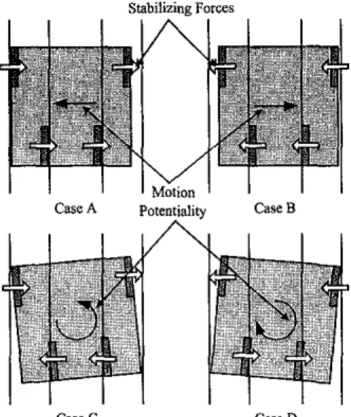
The goals set for the maglev suspension system are the demonstration of stability, decaupling of the degrees of freedom, improvement of rail rigidity, and the robustness to system uncertainties. To make sure our controller can stabilize the maglev suspension system from its unstable nonlinear nature, the responses with respect to four different initial conditions A, B, C, D as indicated in Figure 6 should be tested. However, because of space limitation, only the results of cases A and C are shown. For comparison, an adaptive controller without backstepping [8] is also tested for the maglev system. Figures 7, 8, clearly show that the adaptive backstepping controller achieves superior performance over the adaptive controller without backtepping [SI. The settling time of the adaptive control is about 0.3 sec, and the settling time of our controller is 0.05 sec.
6. Conclusions
In this paper, we first introduce the classification of the maglev suspension systems, and clarify the working principles of our design, which is a repulsive maglev suspension system. Due to the
I lackof the information of magnetic parameters in our system, we
transform the plant model into a parameterized form (21). By (37) applying the adaptive backstepping control, the objective to asymptotically stabilize the system is achieved. The experiment
2 2 results are also orcsented and comoared with adaotive control
Y=$,
.J[::]+;b,
z.l[::]+fb,
z61[:+]
+.!gyg
+.!$r;,& 501
.
~~ 1~~ ~without backstepping [8]. The results demonstrate that our adaptive backstepping control has
By substituting equation (31)
-
(34), the time derivative of V becomesI11 I21 131 141 (53) 9. Reference
P. K. Sinha. Electromaenetic Susoension. "Dvnamics and
.
.
Control". London. Peter peregrinus,'l987.D. Cho, Y. Kato, and D. Spilman, "Sliding Mode and Classical Control of Magnetic Levitation Systems". IEEE Control Syst. Mag., vol. 13,110. 1, pp. 42-48, 1993.
D. L. Atherton, "Maglev using paermagnets", IEEE Trans: Magn.,vol. 16,no. 1.,pp. 146.148, 1980.
M. Morishita, T. Amkizawa, S. Kanda, N. Tamura, and T. Yokoyama, "A new maglev system for magnetically levitated carrier system", 1986 Int. Conf Maglev and Linear Drives, Vancouver, B. C., May 1986. 151 I61 [71
P I
1910. Tsukamoto, K. Yasuda, and J. Z. Chen, 'I A New Magnetic
Levitation System with ac Magnets", IEEE Trans. Maw., vol. 24, no. 2, pp. 1497-1500, 1988.
R. Williams, I. R. Matey, Y. Arie, and I. Rathee, '"The effect of mass and pole strength on the levitation height of the magnet over a superconductor". 1. App. Phys., vol. 65, no, 9, pp. 3583-3585, 1989.
I.Y. Wang. A Magnetic Levitation Silicon Wafer Transpon System. Ph.D. Thesis, The University of Texas at Austin, 1993.
K. N. Wu, and L. L. Chen, "Adaptive control of a four-track maglev system", Journal of Control Systems and Technology 4,4,pp. 295-302, 1996.
Krstic, Kanellakopouslos, and Kokotovi'c, 'Wonlinear and Adaptive Control Design", Wiley Interscience, 1995.
[IO]
E. M. Purcell, Electricity and Magnetism, Berkeley Physics[I I] J. G. David, Introduction to Electrodynamics, Prentice-Hall, Course vol2. McGraw-Hill, 1965.
Inc., Englewood Cliffs, New Jersey, 1981.
Figure 1. Photograph of the physical system
Figure 3. The cross-section of levitation track
Y L
Figure 4. The free body diagram of the carriage aner undergoingx translation and Brotation.
Stabilizing Forces
Case C Case D
Figure 6. Four typical cases of initial condition (IC). Where Case A is the maximum positive translation IC, Case B is the maximum negative translation IC, Case C is the maximum positive rotation
IC, and Case D is the maximum negative rotation IC.
-
~ s h z * t l e ? , . n g m w m-RI [PI - 5 $ ' O F " 0 5 0 0.05 0.1 0.15 0.2 0.25 0.3 0.35 0.4 bm[recl bmegec]Figure 7. Experiment result of initial condition Case A.
I (I 0.05 0.1 0.15 0.2 0.25 0.3 0 . S 0.1 I m r P s l *I
4
0 0.05 0.1 0.15 0.2 0.25 0.3 0.35 0.4:
h
bmelreclFigure 8. Experiment result ofinitial condition Case A.
Table I .
Active Levitator Stabilizer Track A
Track B Track C Track D
Table 2. Parameters list of the model