行政院國家科學委員會專題研究計畫 期末報告
具有未知系統參數之永磁無刷馬達適應自調式控制器設計 與製作
計 畫 類 別 : 個別型
計 畫 編 號 : NSC 101-2221-E-011-005-
執 行 期 間 : 101 年 08 月 01 日至 102 年 07 月 31 日 執 行 單 位 : 國立臺灣科技大學電機工程系
計 畫 主 持 人 : 施慶隆
計畫參與人員: 碩士班研究生-兼任助理人員:田茂陽 碩士班研究生-兼任助理人員:李昇峰
公 開 資 訊 : 本計畫可公開查詢
中 華 民 國 102 年 08 月 13 日
中 文 摘 要 : 本研究論文設計一個可變結構控制器用來控制混合速度與力 矩命令值的表面型永磁同步馬達控制系統,該馬達系統具有 系統參數不確定性以及未知的負載。由於表面型永磁同步馬 達 d 軸與 q 軸的電感值相同,而且只有 q 軸的控制電壓與電 流能夠影響與改變馬達的速度與轉矩;因此系統的控制輸入 變數設為 q 軸的輸入電壓,以及系統的輸出變數設為速度與 力矩的混合值。根據 Lyapunov 穩定性理論。根據永磁同步馬 達速度與轉矩的混合誤差值的線性動態模式建立可變結構控 制器切換平面。在包括有系統參數及負載變動的適當工作條 件下,系統的追蹤誤差具有漸近穩定性。最後由電腦模擬以 及實驗結果可以證明我們所提出的可變結構控制器混合速度 與力矩的控制策略十分具有有效性、強健性及實用性。
中文關鍵詞: 表面型永磁同步馬達、可變結構控制、混合速度與力矩控 制、混合零動態系統、Lyapunov 穩定性
英 文 摘 要 : A variable structure hybrid velocity and torque tracking control (VSHVTTC) for the surface-mount permanent magnet synchronous motor (PMSM) drives (i.e., the inductances of direct and quadrature (i.e., d and q) axes are the same) subject to system uncertainties and load torque is developed. Because the inductances of d and q axes are the same, only q- axis voltage (or current) can affect the driving torque and then angular velocity. Hence, the control input is the input voltage of q-axis; the system output is designed as the hybrid angular velocity and driving torque. Based on Lyapunov stability
criterion, the desired torque is also derived from the mechanical subsystem. It is the function of the nominal load torque, tracking error of angular velocity and system parameters. Then the switching surface is constructed by the linear dynamics of the hybrid tracking errors of angular velocity and
driving torque. Under suitable conditions, an
asymptotical tracking result of the controlled system with uncertainties and load torque is obtained by Lyapunov stability theory. The relative simulations and experiments are presented to evaluate the
usefulness, robustness and practicality of the proposed VSHVTTC.
英文關鍵詞: Surface-mount PMSM drive, Variable structure control,
Velocity and torque control, Lyapunov stability
行政院國家科學委員會補助專題研究計畫 ※成果報告
□期中進度報告
具有未知系統參數之永磁無刷馬達適應自調式控制器設計與製作
計畫類別:※個別型計畫 □整合型計畫 計畫編號:NSC 101-2221-E-011-005
執行期間: 101 年 08 月 01 日至 102 年 07 月 31 日
執行機構及系所:臺灣科技大學電機工程系 計畫主持人:施慶隆
共同主持人:
計畫參與人員:黃志良
成果報告類型(依經費核定清單規定繳交):※精簡報告 □完整報告
中 華 民 國 102 年 07 月 26 日
摘 要
本研究論文設計一個可變結構控制器用來控制混合速度與力矩命令值的表面型永磁同步馬達控 制系統,該馬達系統具有系統參數不確定性以及未知的負載。由於表面型永磁同步馬達 d 軸與 q 軸 的電感值相同,而且只有 q 軸的控制電壓與電流能夠影響與改變馬達的速度與轉矩;因此系統的控 制輸入變數設為 q 軸的輸入電壓,以及系統的輸出變數設為速度與力矩的混合值。根據 Lyapunov 穩定性理論。根據永磁同步馬達速度與轉矩的混合誤差值的線性動態模式建立可變結構控制器切換 平面。在包括有系統參數及負載變動的適當工作條件下,系統的追蹤誤差具有漸近穩定性。最後由 電腦模擬以及實驗結果可以證明我們所提出的可變結構控制器混合速度與力矩的控制策略十分具 有有效性、強健性及實用性。
關鍵字:表面型永磁同步馬達、可變結構控制、混合速度與力矩控制、混合零動態系統、Lyapunov 穩定性
Abstract
A variable structure hybrid velocity and torque tracking control (VSHVTTC) for the surface-mount permanent magnet synchronous motor (PMSM) drives (i.e., the inductances of direct and quadrature (i.e., d and q) axes are the same) subject to system uncertainties and load torque is developed. Because the inductances of d and q axes are the same, only q-axis voltage (or current) can affect the driving torque and then angular velocity. Hence, the control input is the input voltage of q-axis; the system output is designed as the hybrid angular velocity and driving torque. Based on Lyapunov stability criterion, the desired torque is also derived from the mechanical subsystem. It is the function of the nominal load torque, tracking error of angular velocity and system parameters. Then the switching surface is constructed by the linear dynamics of the hybrid tracking errors of angular velocity and driving torque. Under suitable conditions, an asymptotical tracking result of the controlled system with uncertainties and load torque is obtained by Lyapunov stability theory. The relative simulations and experiments are presented to evaluate the usefulness, robustness and practicality of the proposed VSHVTTC.
Keywords--- Surface-mount PMSM drive, Variable structure control, Velocity and torque control, Lyapunov stability.
I.
IntroductionHigh torque permanent magnet synchronous motors (PMSMs) are becoming an increasingly popular selection in low to medium speed industrial motor applications where torque density and efficiency are critical. In comparison with induction motors, permanent magnet machines typically have lower inductance and a greater number of poles, yielding a small electrical time constant which leads control designers toward high-frequency commutation solutions as a means to generate sufficiently smooth stator currents. However, as the phase currents become large, as is typical in low-speed high-power applications, the maximum attainable switching frequency shrinks as a result of the thermal limitations of the switching elements. In this situation, the control engineer is encountered with the difficulty of maximized performance of the closed-loop system with a highly constrained actuator.
There have many papers discussing the torque control of PMSM drives. Some representative papers (e.g., [1]-[8]) are introduced as follows. In [1], Zhong et al. discussed a direct torque controller for a PMSM. A hybrid-type variable- structure controller with internal model for the flux harmonics and system uncertainties was developed to obtain better disturbance rejection without control chattering [2].
Integration of non-linear H and sliding mode control techniques for the motion control of a PMSM was designed by Ghafari-Kashani et al. [3]. The robust current controller developed by Chou et al. [4] was augmented with a command feed-forward controller and a simple observed disturbance robust cancellation controller. It was effective in handling sinusoidal PMSM varying-frequency winding current tracking control under sinusoidal back electromotive force (EMF) disturbance. In addition, the model predictive direct torque control with finite control set for PMSM drives was developed by Preindl and Bolognani [5]. Furthermore, direct torque control of brushless DC drives with reduced torque ripple was established by Liu et al. [6]. Similarly, a switching control strategy for the reduction of torque ripple for PMSM was discussed by Jezernik et al. [7]. Xia et al [8] proposed a unified approach for suppressing commutation torque ripple over the entire speed range and overcame the difficulties of commutated-phase-current control.
On the other hand, precise position control is becoming increasingly important in applications such as chip mount machines, semiconductor production machines, precision milling machines, high-resolution CNC machines, precision assembly robots and high-speed hard disk drives. In many applications, a PMSM has replaced the conventional DC motor because the trend is for industrial applications to require more powerful actuators with smaller sizes. It is known that a PMSM has a low inertia, a large power-to -volume ratio, and a low noise level as compared to a permanent-magnet DC servomotor with the same output rating. However, the disadvantages of this machine are a high cost and the requirement for a more complex controller because of its nonlinear characteristics.
There have many papers addressing the position (or
velocity) control of various PMSM drives. Some representative papers (e.g., [9]-[18]) are given as follows. The compared positioning between variable structure control and linear-quadratic control was discussed by Shyu et al. [9]. The spatial information obtained from the estimated saliency- based EMF was used in an observer to estimate the motor motion states. Precise position control of a PMSM with a disturbance observer containing a system parameter compensator was developed by Choi et al. [10]. In addition, the online trained wavelet neural network control was utilized to predict the uncertain system dynamics to relax the requirement of uncertainty bound in the design of the H∞
controller [11]. Quasi-(and fuzzy) sliding mode approach for robust speed control of PMSMs were designed by Corradini et al. [12], and Leu et al. [13], Choi et al. [14], respectively.
FPGA-based speed tracking control was developed by Alecsa et al. [15]. The input-output feedback-linearization-based nonlinear transform with a speed controller for the converted linear model was designed by Xia et al. [16] to reject some parameter perturbations. Similarly, the fuzzy adaptive controller based on internal model principle and saturated control input was designed to automatically tune the parameter of speed controller [17]. Finally, a nonlinear speed-control algorithm for the PMSM servo systems using sliding-mode control and disturbance compensation techniques is developed [18] to optimize the speed-control performance of PMSM system with different disturbances and uncertainties.
However, no paper discusses the simultaneous control of angular velocity and driving torque for the surface-mount PMSM drives. In this paper, a variable structure hybrid velocity and torque tracking control (VSHVTTC) for the surface-mount PMSM drives subject to uncertainties and load torque is developed. Because the instances of d and q axes are the same, only voltage or current of q-axis affects the driving torque or angular velocity. In summary, only one input (e.g., voltage of q-axis) is employed to control the torque and velocity. On the other hand, the output is the linear combination of angular velocity and driving torque.
Then the switching surface is constructed by the linear dynamics of the hybrid tracking errors of velocity and torque.
The first weight of hybrid output is in response to the velocity tracking of the surface-mount PMSM drive; on the other hand, the second weight is in response to its torque tracking. Under suitable conditions, an asymptotical tracking result of the controlled system with uncertainties and load torque is accomplished by Lyapunov stability theory. The simulations and experiments are simultaneously presented to evaluate the usefulness, robustness and practicality of the proposed VSHVTTC.
II. Experimental Setup, Mathematical Model and Problem Formulation
Three subsections are included in this section, namely, experimental setup, mathematical model, and problem formulation.
A. Experimental Setup
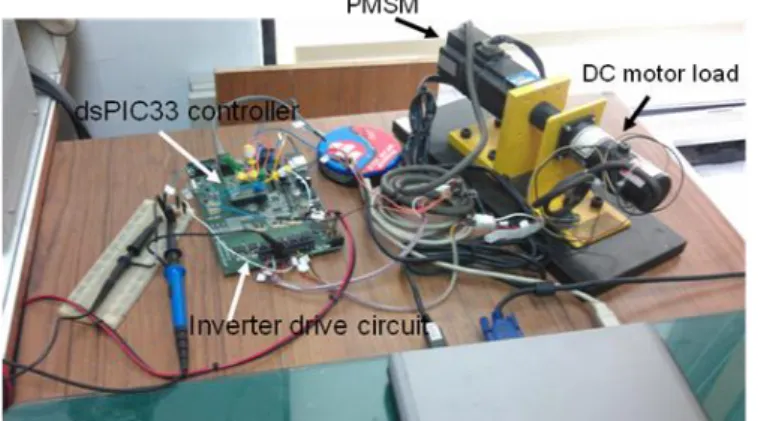
The platform system of PMSM drive is shown in Fig. 1 and the motor and system parameters are listed in Table 1.
Microchip 16-bit dsPIC33 digital signal controller is adopted in the control system, and its system clock rate is 40 MHz.
The rotor position and the motor speed are estimated By means of three Hall sensors. The PMSM motor currents are measured by two shunt resistors with OP amplifier circuit, and input to the dsPIC33’s 10-bit analog-digital converter (ADC). The inverter SVPWM (Space Vector PWM) switching frequency, ADC sampling rate and control law sampling rate adopt the same frequency as 20 kHz. Besides
d( )
i t is regulated to zero by a PI control, the signals i t and q( )
r( )t
are feedback to the proposed variable structure hybrid velocity and torque tracking control (VSHVTTC) for tracking the desired hybrid motor velocity and torque. In summary, the proposed VSHVTTC and the vector control scheme of the PMSM drive is illustrate in Fig. 2.
Fig. 1. The experimental system consisting of PMSM, DC motor load, dsPIC33 controller and inverter drive circuit.
PMSM and Inverter Drive Circuit
+ _
VSHVTTC PI Regulator
0 1
JsB
1 s a, ,b c
i i i
2 p
, ,
a b c
v v v
id
iq 1d 2d
r ww
vd
vq
l
r
Transformation abc dq Transformation
dq abc r
Fig. 2. The proposed VSHSTTC and the vector control scheme of the PMSM drive.
B. Mathematical Model
Besides the specification of the proposed PMSM drive in Table 1, it possesses the rate voltage of 30V, rate current of 0.5A, and rate speed 500rpm, respectively. The dynamic model of surface-mount PMSM for magnetic isotropic and anisotropic machines written in the dq reference frame is as follows:
( ) ( )
( ) ( )
( ) ( )
( ) ( )
( ) ( ) ( )
( ) ( )
( ) ( ) ( ) ( )
r r
l r
r
d d q
d r q
d d d
q q d m
q r d r
q q q q
d t
dt t
t t
d t B
dt J t J
di t v t R L
i t p t i t
dt L L L
di t v t R L
i t p t i t p t
dt L L L L
(1)
( ) 3 ( )
2
pm q
t i t (2 ) wherer( ) and t r( )t are the shaft rotational position and velocity, respectively; p is the number of magnetic pole pairs;
m is the magnetic flux; Ld and ( ), i td Lq and ( )i t are the q currents and inductances of direct and quadrature axes, respectively; Bis the damping coefficient; J is the rotor moment of inertia; ( )t is the driving torque;l( )t is the load torque; R is the stator resistance; and v td( ) and ( )v t are the q input voltages of direct and quadrature axes, respectively.
Because LdL for surface-mount PMSM drives, only q
( ) or ( )
q q
v t i t can affect the driving torque ( )t or angular velocityr( ),t as shown in (2). In summary, only one input (e.g.,v tq( ))is employed to control the hybrid velocity and torque.
Table 1. System parameters.
Symbol Description Value
p Number of magnetic pole pairs 2
m Magnetic flux 0.1428 Wb
B Damping coefficient 2.54 10 3Nm-sec/
rad J Rotor moment of inertia 8.96 10 4Kg m2 Ld Inductance of d axis 1.33 10 H 2 L q Inductance of q axis 1.33 10 H 2
R Resistance 20.6
To express the system (1) in a matrix form, the following four states:x t1( )r( ),t x t2( )r( ),t x t3( )i td( ),andx t4( )i tq( ), one input: ( )u t v t one hybrid output:q( ), y t( )w1r( )t w t2( ), wherew w1, 20are weights, are defined. Then the system in matrix form is given as follows:
( ) ( , ) ( , ) ( ),
X t A X t B X t u t y t( )c X t( , ) ( 3 ) whereX tT( )
x t1( ) x t2( ) x t3( ) x t4( )
4is the system state,( ) and ( )
u t y t is the control input and system output, respectively. Furthermore, the corresponding nominal and uncertain system (vector) and output functions are as follows:
4 4
( , ) ( ) ( , )
( , ) ( ) ( , )
( , ) ( ) ( , )
A X t A X A X t B X t B X B X t c X t c X c X t
( 4 a ) where the components of the nominal system vector and output functions are expressed as follows:
a1( X) x2( ) , t 2a X(
) B x2 ( )t 4
x ( )t J
3 3 2 4
4 4 2 3 2
( ) ( ) ( ) ( )
( ) ( ) ( ) ( ) ( )
q ( ) d
m d
d q
a X Rx t pL x t x t L
a X Rx t pL x t x t p x t L v t
( ) 0, 1, 2,3, ( ) 14
i q
b X i b X L (4b)
1 2 2 4
( ) ( ) ( ),3 m 2.
c X w x t w x t p On the other hand, the nonzero components of uncertain system vector and output functions are given as follows:
( , ), 1, 2,3, 4, 4( , ), ( , ).
a X t ii b X t c X t
(4c)
Remark 1: In addition,
0
( ) p ( ) i t ( ) ,
d d t d
v t d e t d
e d where ( ) 0 ( ),d d
e t i t anddp, di0.
Remark 2: The load torque
l( )t is supposed to be known such that the proposed control is designed to resist the load torque. Hence, it is separated into the following two parts:l( )t l( )t l t( ) (5a) wherel( )t andl( )t are denoted as the nominal and uncertain load torque, respectively. Under the capability of PMSM drive, hybrid velocity and torque control is applied to obtain high required performance, e.g., (hybrid) electrical vehicle [19], [20]. Then part of equation in (4b) and (4c) must be modified as follows:
2( ) 2( ) 4( ) l( )
a X Bx t x t t J (5b)
2( , ) l( ) .
a X t t J
(5c) Besides unknown uncertainties for uncertain component
2( , ), a X t
eqn. (5c) implies that it is also caused by variation load toque.
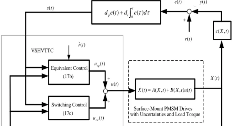
( ) ( , ) ( , ) ( ) X tA X tB X t u t ( )
r t
( ) X t ( )
u t
( ) e t
Surface-Mount PMSM Drives with Uncertainties and Load Torque VSHVTTC
Switching Control (17c) Equivalent Control (17b)
( ) 0t( )
p i
d e t d e d
( , ) c X t
( ) y t
( )
s t
eq( ) u t
sw( ) u t
( ) r t
Fig. 3. Control block diagram of the overall surface-mount PMSM drives.
C. Problem Formulation
Before discussing the problem formulation, hybrid tracking error is defined as follows:
e t( )r t( )y t( ) . ( 6 ) where r t( )w1d( )t w2d( ),t d( ) and ( )t d t are the desired angular velocity and driving torque, respectively. Equation (6) can be rewritten as follows:
e t( )w e t1 1( )w e t2 2( ) (7) wheree t1( )d( )t r( ) and ( )t e t2 d( )t ( )t are the tracking errors of angular velocity and driving torque, respectively.
The problem is to design the control input for the surface- mount PMSM drives (3)~(5) subject to uncertainties (i.e., A X t( , ),B X t( , ),c X t( , )) such that the output boundedly or asymptotically tracks a reference input
( )
r t (refer to Fig. 3). Then the proposed variable structure hybrid velocity and torque tracking control (VSHVTTC) for completely and partially known load torque, for the system without or with uncertainties, for different weights are first simulated to evaluate the effectiveness and robustness of the proposed control. Finally, the corresponding experiments are arranged to confirm the practicality of the proposed method.
III. Variable Structure Hybrid Velocity and Torque Tracking Control
The proposed variable structure hybrid velocity and torque tracking control (VSHVTTC) is designed as follows.
The switching surface is first defined as
0
( ) p ( ) i t ( )
s t d e t d
t e d ( 8 ) wheredp0, sgn d d
p i 1, and ( )s t .Then, the dynamics of the switching surface (8) is rewritten as follows:e t( )ge t( )hs t ( ) ( 9 a ) where
0
( ) t ( ) , i p, 1 p.
e t
t e d g d d h d (9b) Then, the solution of (9) is given as follows:
0
0 0
0
( ) exp[ ( )] ( )
t exp[ ( )] ( ) , .
t
e t g t t e t
g t hs d t t
(10)Lemma 1[21]: If the stable switching surface (8) satisfies the following inequality hs t( )1e t( ) , for tt0, where 0 1 d d , and its initial conditioni p e t( )0 is bounded, then
( ), ( )0
e t e t with a rate
d di p1
as tt0.Lemma 2 [21]: If the stable switching surface (8) satisfies the following inequality hs t( )2, fortt0, and its initial condition
( )0
e t is bounded,
thene t( )2dp di or ( )e t 22ast.
Because the derivative of the proposed control needs the time-derivative of switching surface, the following equation is first derived.
1 2 2
2 4 4 4 4
( , ) ( ) ( , )
( ) ( , )
( ) ( , ) ( ) ( ) ( , )
( , )
( ) ( ) ( ) ( , ) ( ) ( , ) c X t c X c X t
w a X a X t
w a X a X t u t b X b X t
c X t
f X X u t X t u t X t
(11 )
where
1 2 2 4
2 4 2 4
1 2 2 2 4
( ) ( ) ( )
( ) ( ), ( , ) ( , )
( , ) ( , ) ( , ) ( , )
f X w a X w a X
X w b X X t w b X t
X t w a X t w a X t c X t
(12) It is also assumed that the uncertainty of control gain satisfies the following inequality:
1( ) ( , ) 1, ( ), .
X X t X t t (13) Furthermore, the upper bound of the following uncertainty is supposed to be true.
q X u( , eq, )t 0 1p X u( , eq) (14a) where
0 and 1
are positive constants determined by the stability of the closed-loop system; p X u( , eq)is positive scalar function; and
( , eq, ) p ( , ) eq( )( , )
q X u t d X t u t X t (14b) whereueq( )t is the equivalent part of the proposed VSHVTTC (cf. (17b)).
Moreover, how to assign an effective desired driving torque, i.e., d( ),t such that under nominal environment r( )t d( )t as t , is designed in the following Lemma.
Lemma 3: Consider the nominal mechanical subsystem of the surface-mount PMSM drives, i.e.,
1 2
2 2
( ) ( )
( ) ( ) ( ) l( ) .
x t x t
x t Bx t t t J
(15) Then the desired torque ( )t d( )t in (16) can obtain the goal r( )t d( )t as t .
d( )t l( )t B x2 ( ) +t Jd ( )t 1 1k e t ( ) (16) ( )t where
0
1 1 1
( ) ( ) ( ) ,
t t
t e t k e d
theconstant k1> 0, 0 denotes the convergent rate to ( )t 0,
andl( )t is known.
In addition, the definition of uniformly ultimately bounded (UUB) is described as follows.
Definition 1 [22]: The solutions of a dynamic system are said to be UUB if there exist positive constants and , and for every(0, ) there is a positive constantT T ( ), such that X t( )0 X t( ) , t t0 T.
The VSHVTTC for the surface-mount PMSM drives is designed as follows:
( ) eq( ) sw( )
u t u t u t (17a) ueq( )t
d r tp
( )f X(
)d e ti
( )dp X ( (17b) ) usw( )t 1s t( )2s t( )
s t( )
dp( ) 1X
(17c) where the first two switching gains 1, 2 2 0, where is the exponential convergent rate to the switching surface (8);
0 is the boundary layers of the switching surface;0 is the upper bound of the uncertain control gain and described in (13).
Then the result of the VSHVTTC for the surface-mount PMSM drives is addressed as follows.
Theorem 1: Applying the control law (17) to the system (3)- (4) with the known upper bounds of uncertainties (13) and (14), gives the finite time to reach the switching surface (8), satisfying the following convex setDs:
( ) ( )
s s
D s t s t s (1 8) where
1 12 4 2 0
2 2
ss m m m m m (19a)
2 1
1 2 1 0 1
0 0 1
2 0,
2 ,
0.
m
m p
m p
(19b)
Then
X t u t( ), ( )
are UUB. If hs t( )1e t( ) ,where 0 1 d di p, then e t( )0 with the rate
d di p1
ast.Remark 3: The first weight of hybrid output (or tracking error), i.e., w1,is in response to the velocity tracking of the surface-mount PMSM drives; on the other hand, w2is in response to its tracking of driving torque.
Remark 4: Because the time derivative of desired driving torque in ( ),r t , i.e.,d( ),t for the ueq( )t in (17b) is complex, it is approximated by its difference, i.e., d( )t
d(kTs)d((k1) )Ts
Ts, where Ts is the sampling time. The uncertainty caused by the approximation of d( )t can be represented by ( ,q X ueq, )t in (14b).In general, the smaller sampling time is chosen, the smaller approximation error is obtained.Remark 4: The proposed concept can be extended to hybrid angular position and driving torque tracking control. For brevity, it is omitted.
Corollary 1: If the switching gains
1is chosen larger enough such that 4m m m2 0 121, m10, andif m0 (2m1)1dp e t( ) , where 0 1 d di p, then
( )0
e t with the rate
d di p1
ast.Remark 5 The result of Corollary 1 indicates that larger switching gain can deal with larger uncertainty to obtain the asymptotical tracking result. However, the chattering control input or the saturated control input occurs.
Finally, the proposed VSHVTTC for the surface-mount PMSM drives is summarized as follows.
Step 1:To obtain the nominal model of a surface-mount PMSM drive, i.e., ( ), ( ),A X B X andc X( ).
Step 2: Based on the assigned task, the desired angular velocity is planned. Then the desired torque is obtained from (16). The coefficients of the switching surface (8) are set, i.e.,dp and .d i
Step 3: The uncertainty, i.e., ( ,q X ueq, ),t is estimated by (14a), i.e., 01p X u( , eq). On the other hand, the uncertainty of control gain, i.e.,( , ),X t is estimated by (13).
Step 4: Then the proposed VSHVTTC with suitable control parameters is achieved by (17) and (20).
Step 5: At steady state, s t( ) ss,described in (18) and (19), is achieved.
Step 6: If s t( ) is not small enough, appropriate control parameters should be tuned again. If the result is still not excellent, it goes back to Step 1.
IV. Simulations
The system parameters including the parameters of a surface-mount PMSM drive, the coefficients of nominal torque are given in Table 1. Furthermore, the suitable control parameters are assigned in Table 2. Based on the proposed PMSM drive in section II, the saturated control input v t of q( ) 30 volt is considered. All initial states are zero, i.e.,
(0) 0.
X
Table 2. Control parameters.
Symbol Description Value
Boundary layers of s 0.1
Upper bound of control gain 0.1d p Proportional gain of s 10
di Integral gain of s 0.5
1 Switching gain of s 100
2 Switching gain of s 8
0, 1
Coefficients of uncertainty 0.1,1.1
1,
k Coefficients for the desired torque 5, 0.5
1, 2
w w Weights for the hybrid output 0.5,0.5
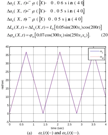
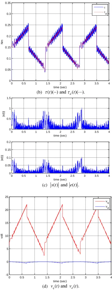
At beginning, the simulations with small nominal load
torque (i.e.,l( )t 0.05Nm) as well as without uncertainties are conducted for tracking a desired saw-teeth trajectory with 0.725Hz in frequency and 37.699rad/sec (i.e., 360rpm) in magnituded( ).t The corresponding response is shown in Fig.
4. It indicates that the proposed controller possesses good tracking ability. For verifying the resistance of load torque, the response for a huge nominal load torque (e.g.,l( )t 0.3Nm) of Figure 4 case is presented in Fig. 5. If a load torque is over the capability of the proposed PMSM drive, the saturated control input (i.e., 30 volt) occurs and then tracking performance is deteriorated (cf. Fig. 4(a) and Fig. 5(a)). Due to the larger nominal load torque, the desired torque in (16) becomes larger. Therefore, the response of torque in Fig. 5(b) is also larger than that in Fig. 4(b). The other responses of Fig. 5 are almost the same as that in Fig. 4.
In addition, the response of Fig. 4 with the weightsw10.9 and w20.1is shown in Fig. 6. It reveals that the control input in Fig. 6(d) is slightly discontinuous as compared with that in Fig. 4(d). For verifying the robustness of the proposed control, the following uncertainties (20) are plunged into the Figure 4 case. The corresponding response is presented in Fig. 7, which is still satisfactory.
a X t1( , ) a X1( ) 0.02sin(20 ) cos(30 )
x1 t
2( , ) 2 ( ) 0 . 0 6 s i n ( 4 0 ) s i n ( 3 01 )
a X t a X t x
3( , ) 3 ( ) 0 . 0 5 s i n ( 4 0 ) c o s ( 3 01 )
a X t a X t x
4( , ) 4 ( ) 0 . 0 5 s i n ( 4 01 ) c o s ( 5 0 )
a X t a X x t
1
( , ) ( , ) 0.05sin(200 ) cos(200 )
d q d
L X t L X t L x t
1 3 4
( , ) 0.07cos(300 )sin(250 ) .
m X t m x x x
(20)
0 0.5 1 1.5 2 2.5 3 3.5 4
-5 0 5 10 15 20 25 30 35 40
rad/sec
time (sec)
r
d
(a) r( )( ) and t d( )( ).t
0 0.5 1 1.5 2 2.5 3 3.5 4 0
0.05 0.1 0.15 0.2 0.25
Nm
time (sec)
d
(b) ( )( ) and t d( )( ).t
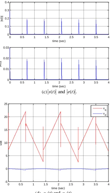
0 0.5 1 1.5 2 2.5 3 3.5 4
0 0.2 0.4 0.6 0.8
|s(t)|
time (sec)
0 0.5 1 1.5 2 2.5 3 3.5 4
0 0.02 0.04 0.06 0.08
|e(t)|
time (sec)
(c) s t( ) ( ) and ( ) ( ). e t
0 0.5 1 1.5 2 2.5 3 3.5 4
-5 0 5 10 15 20 25
volt
time (sec)
vq vd
(d) v tq( ) and ( ).v td
Fig. 4. Response for tracking a saw-teeth velocity using the control parameters in Table 2
0 0.5 1 1.5 2 2.5 3 3.5 4
-5 0 5 10 15 20 25 30 35 40
rad/sec
time (sec)
r
d
(a) r( )( ) and t d( )( ).t
0 0.5 1 1.5 2 2.5 3 3.5 4
0 0.1 0.2 0.3 0.4 0.5 0.6 0.7
Nm
time (sec)
d
(b) ( )( ) and t d( )( ).t
0 0.5 1 1.5 2 2.5 3 3.5 4
0 2 4 6 8
|s(t)|
time (sec)
0 0.5 1 1.5 2 2.5 3 3.5 4
0 0.2 0.4 0.6 0.8
|e(t)|
time (sec)
(c)s t( ) and ( ) .e t
0 0.5 1 1.5 2 2.5 3 3.5 4 -5
0 5 10 15 20 25 30
volt
time (sec)
vq vd
(d) v tq( ) and ( ).v td
Fig. 5. Response for Figure 4 case exceptl( )t 0.3Nm.
0 0.5 1 1.5 2 2.5 3 3.5 4
-5 0 5 10 15 20 25 30 35 40
rad/sec
time (sec)
r
d
(a)r( )( ) and t d( )( ).t
0 0.5 1 1.5 2 2.5 3 3.5 4
0 0.05 0.1 0.15 0.2 0.25
Nm
time (sec)
d
(b)( )( ) and t d( )( ).t
0 0.5 1 1.5 2 2.5 3 3.5 4
0 0.1 0.2 0.3 0.4
|s(t)|
time (sec)
0 0.5 1 1.5 2 2.5 3 3.5 4
0 0.01 0.02 0.03
|e(t)|
time (sec)
(c)s t( ) and ( ) .e t
0 0.5 1 1.5 2 2.5 3 3.5 4
-5 0 5 10 15 20 25
volt
time (sec)
vq vd
(d) v tq( ) and ( ).v td
Fig. 6. Response for Figure 4 exceptw10.9 and w20.1.
0 0.5 1 1.5 2 2.5 3 3.5 4
-5 0 5 10 15 20 25 30 35 40
rad/sec
time (sec)
r
d
(a) r( )( ) and t d( )( ).t
0 0.5 1 1.5 2 2.5 3 3.5 4 0
0.05 0.1 0.15 0.2 0.25 0.3 0.35
Nm
time (sec)
d
(b) ( )( ) and t d( )( ).t
0 0.5 1 1.5 2 2.5 3 3.5 4
0 0.5 1 1.5
|s(t)|
time (sec)
0 0.5 1 1.5 2 2.5 3 3.5 4
0 0.05 0.1 0.15 0.2
|e(t)|
time (sec)
(c) s t( ) and ( ) .e t
0 0.5 1 1.5 2 2.5 3 3.5 4
-5 0 5 10 15 20 25
volt
time (sec)
vq vd
(d) v tq( ) and ( ).v td
Fig. 7. Response for Figure 4 with uncertainties (20).
In the above thorough simulations, the following
important observations are drawn: (i) Under the specific requirement of load torque (i.e.,
l( ) t
), the hybrid velocity and torque of PMSM drive is effectively controlled by the proposed control. It implies that under the capability of PMSM drive, the above specifications is achieved by the proposed control (cf. Fig. 4 and Fig. 5). It can satisfy the high performance of (hybrid) electric vehicle (e.g., [19], [20]). (ii) The selection of suitable control parameters is not critical to obtain satisfactory results including tracking performance and the response of control input (cf. Figs. 4 and 6). Moreover, the proposed control presents its strong robustness for large uncertainties (cf. Figs. 4 and 7). (iii) Besides saw-teeth trajectory, any bounded and smooth reference trajectories can be applied to the proposed VSHVTTC. In addition, it can be extended to hybrid position and torque control of PMSM drives.V. Experiments
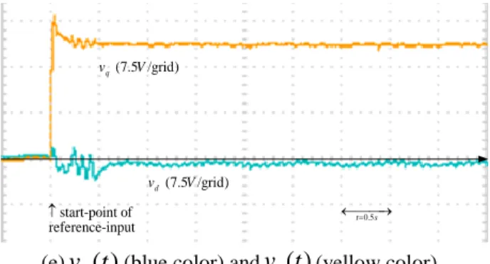
In the beginning, the open-loop responses of the proposed PMSM drive by step input and sinusoidal input are presented to realize its characteristic. Then the corresponding experiments of the PMSM drive only with low-cost rotor position and motor current sensors by the proposed VSHSTTC algorithm are shown in the subsection 2.
A. Open-loop response
Two open-loop responses are examined to realize the dynamic and static features of the proposed surface-mount PMSM drive. The step response for v tq( ) 13.5 V is presented in Fig. 8. From Fig. 8, it implies that the proposed PMSM drive contains high frequency noises, and that the currenti t (or q( ) i ta( ), ( )i t ) or torqueb ( )t is more lightly damped as compared with the angular velocity r( ).t Similarly, the response for v tq( ) 6.75 1 sin(2 )
t V
is presented in Fig. 9. From Fig. 9, it indicates that the proposed PMSM drive is highly nonlinear and contains lightly damped mode. Therefore, the controller design of the proposed PMSM will be a challenge.0.5 t s
(7.5 /grid ) vq V
(150 /grid)
r rpm
start-point of step-input
(a)v tq( )(blue color) andr( )t (yellow color)
0.5 t s
(7.5 /grid) vq V
(0.125 /grid)
iq A
start-point of step-input
(b)v t (blue color) and ( )q( ) i t (yellow color). q
0.5 t s
(0.125 /grid)
ia A
(0.125 /grid)
ib A
start-point of step-input
(c)i ta( )(yellow color) andi tb( )(blue color) Fig. 8. Step response forv tq( )13.5 .V
0.5 t s
(7.5 /grid) vq V
(150 /grid)
r rpm
start-point of sinusoidal-input
(a)v tq( )(blue color) andr( )t (yellow color).
0.5 t s
(0.125 /grid)
iq A
(0.75 /grid) vq V
start-point of sinusoidal-input
(b)v t (blue color) andq( ) iq(t)(yellow color).
Fig. 9. Sinusoidal responses ofv tq( ) 6.75 1 sin(2 ) .
t V
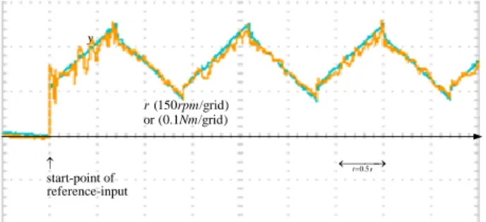
B. Hybrid trajectory tracking response
Figure 10 shows the tracking response of the saw-teeth speed trajectory with 0.725Hz and 360rpm, and nominal load torquel( )t 0.05Nmby the proposed VSHSTTC using the control parameters in Table 2.
0.5 t s
(150 /grid) or (0.1 /grid)
r rpm
Nm y
start-point of reference-input
(a)r t( )(blue color) andy t( )(yellow color).
0 .5 t s
(150 /grid)
d rpm
(150 /grid)
r rpm
start-point of reference-input
(b)
d(t )
(blue color) andr( )t (yellow color).0 .5
t s
(0.1Nm/grid)
(0.1 /grid)
d Nm
start-point of reference-input
(c)d( )t (blue color) and( )t (yellow color).
0.5 t s
e s
start-point of reference-input
(d)
s (t )
(blue color) ande (t )
(yellow color).0.5 t s
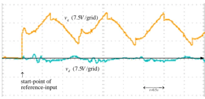
(7.5 /grid) vd V (7.5 /grid) vq V
start-point of reference-input
(e)
v
d(t )
(blue color) andv
q(t)(yellow color).Fig. 10. Response of hybrid saw-teeth velocity and nominal load torquel0.05Nmby the proposed VSHSTTC with
the control parameters in Table 2.
The tracking response of Figure 10 case with
1 0.9 and 2 0.1
w w is presented in Fig. 11. Figure 12 shows the tracking response of Figure 10 case with load torquel( )t 0.1Nm.
0.5 t s
y
start-point of reference-input
(150 /grid) or (0.1 /grid)
r rpm
Nm
(a)
r (t )
(blue color) andy (t )
(yellow color).0.5 t s
(150 /grid)
d rpm
(150 /grid)
r rpm
start-point of reference-input
(b)d( )t (blue color) andr( )t (yellow color).
(0.1Nm/grid)
(0.1 /grid)
d Nm
start-point of reference-input
0.5 t s
(c)
d(blue color) and (t )
(yellow color).0.5 t s
e (7.5 /grid)
s V
start-point of reference-input
(d)
s (t )
(blue color) ande (t )
(yellow color).0.5 t s
(7.5 /grid) vd V
(7.5 /grid) vq V
start-point of reference-input
(e)
v
d(t )
(blue color) andv
q(t)(yellow color).Fig. 11. Response of Figure 10 case withw10.9 and w20.1.
0.5 t s
y
start-point of reference-input
(150 /grid) or (0.1 /grid)
r rpm
Nm
(a) ( )r t (blue color) and ( )y t (yellow color).
0 .5 t s
(150 /grid)
d rpm
(150 /grid)
r rpm
start-point of reference-input
(b)d( )t (blue color) andr( )t (yellow color).
0 .5 t s
(0.1Nm/grid)
(0.1 /grid)
d Nm
start-point of reference-input
(c)d( )t (blue color) and
(t )
(yellow color).0.5 t s
e
(7.5 /grid)
s V
start-point of reference-input
(d)