Scalar Control of Double-Stator Permanent Magnet Brushless Motor Drives
Shuangxia Niu and Linni Jian
Department of Electrical and Electronic Engineering The University of Hong Kong
Pokfulam Road, Hong Kong SAR, China [email protected], [email protected]
Abstract—This paper presents a new scalar-controlled double- stator permanent magnet brushless (DS-PMBL) motor. Because of the special phase decoupling structure, scalar control strategy is newly incorporated into the time-stepping finite element method (TS-FEM) to analyze the transient performance of machine. The complicated coordinate transformation is avoided and constant torque and flux weakening control operation is obtained. Based on the time-stepping finite element method (TS- FEM), the torque-speed capability and the transient responses at startup, sudden load change and sudden command change are simulated to verify the validity of the proposed scalar control.
Experimental results verified the validity of the analysis method.
Keywords-scalar control; TS-FEM; double-stator cup-rotor PM motor drive
I. INTRODUCTION
Electric motor drives are the key technology for electric vehicles (EVs) [1-8]. Among them, the family of permanent magnet brushless (PMBL) motor drives is most promising [9- 16]. Particularly, its double-stator (DS) topology, namely the DS-PMBL motor drive, has been identified to be attractive for EVs, because of its high torque density for launching and wide constant power operating range for cruising [17-20]. However, the corresponding controllability is still hindered by the use of complicated vector control. Also, the corresponding transient field analysis is absent in literature, which is probably due to its control complexity when using the time-stepping finite element method (TS-FEM) [21-24]. Recently, the concept of scalar control has been proposed for phase-decoupling PMBL motor drives, which can significantly reduce the control complexity [25].
The purpose of this paper is to propose and implement the scalar control strategy for DS-PMBL motor drive, thus avoiding the use of complicated coordinate transformation for vector control. Consequently, the corresponding transient field analysis, covering both constant torque operation and flux weakening operation, will be performed by using the time- stepping finite element method (TS-FEM). Based on the TS- FEM, both the transient responses and torque-speed capabilities will be used to illustrate the validity of the proposed scalar control. Finally, a 2-kW prototype will be tested for experimental verification.
II. MOTOR CONFIGURATION
As shown in Fig. 1, the DS-PMBL motor is so unique that it has two 3-phase 24-slot concentric stators and a 22-pole cup- shaped rotor. This structure offers a high torque density and high efficiency. The winding distribution is shown in Fig. 2.
Using TS-FEM, the magnetic field distributions for the calculation of single phase inductance is simulated in Fig. 3.
The self inductance and mutual inductance can be obtained as 0.3173 mH and zero respectively. This DS-PMBL motor has many advantageous features as following:
Since the phase windings are essentially magnetically isolated, the mutual inductances among different phases become negligible. This phase-decoupling nature enables the motor adopting a simple scalar control strategy, instead of using complicated coordinate transformation for vector control.
Currents of both the inner and outer stators produce electromagnetic torque and two air-gaps deliver output torque.
Compared with the single stator PM machine with the same volume and only one air-gap to deliver torque, the structure of the DSCR PM machine is more compact and the torque density is improved.
The rotor core is designed like a cup with PMs mounted on its inner and outer surfaces. The magnetic flux path is in series, so the iron core of rotor can be designed very thin.
Compared with the magnetic flux path in parallel, this cup-type rotor can effectively shorten the magnetic circuit length and hence improve the torque density.
This PM machine adopts fractional slot concentrated windings arrangement. If it has alternate teeth wound with coils, since the coil span of stator windings is designed to have one slot pitch, the phase flux paths are independent. In this sense, the mutual inductance of phase windings is negligible, hence the controllability is improved.
The fractional-slot concentrated winding arrangement can shorten the end-winding, thus improving the utilization of copper materials, and reducing the copper losses. Hence the efficiency of machine is increased [26-29].
Since the proposed machine has 24 slots in each stator and 22 poles totally, the slot pitch is 11/12 pole pitch. Due to that the cogging torque caused by the slotting is approximately
related to the inverse of the smallest common multiple of the number of slots and number of pole pairs [30-31], this arrangement of fractional number of slots per pole per phase can significantly reduce the cogging torque that usually occurs in PM motors.
The multi-pole structure leads to minimized core yoke height, and reduced iron mass. This structure can further save the material and increase the torque density of machine.
The inner and outer stators have independent windings set, so the six terminals of each sets can be connected flexibly to obtain the desired output voltage [32-35].
The inner and outer stator windings can be used simultaneously or operated independently. When one set of windings is out of work, the machine can continue work well with the other set of stator windings. Hence, the fault tolerance capability of the DSCR PM machine is improved.
It should be noted that, the rated current density of the proposed DSCR PM machine is only 2.2 A/mm2, so there is no need to apply sophisticated cooling. In case the working environment is abominable, an external fan may be used to provide forced cooling for the inner stator.
Figure 1. DS-PMBL motor configuration.
Figure 2. Single-layer winding connection diagram.
Figure 3. Magnetic field distributions for the calculation of phase inductance.
III. SCALAR CONTROL AND TS-FEMANALYSIS 2D TS-FEM is used to model the operation of proposed motor. In this model, the electromagnetic field, circuit and mechanical motion equations are coupled together and solved simultaneously at each time step. The governing equation of the magnetic field is presented by Maxwell’ equation, which is given by,
( ×A)=J+ (∇×M)
×
∇ ν ν (1)
where ν , A , J and M are the reluctivity of material, magnetic vector potential, current density, and magnetization of PM, respectively. The phase circuit equation is expressed by,
dt e Ldi Ri
Vs = s+ s + (2)
where Vs is the supply voltage, R is the winding resistance, e is the back EMF, i is the stator current and L is the end s winding inductance. The mechanical equation governing the rotor motion is given by
f e f
m T T
dt
J dω+α ω= − (3)
where J is the moment of inertia, m ω is the rotor speed, T is e the electromagnetic torque, T is the load torque, and f αf is the coefficient of friction. The Galerkin’s method is used to derive the system matrix equations and the backward Euler difference method is used to discretize the system equation in time domain. At each time step, the vector potential A and current i can be calculated directly. Torques T can be e calculated accordingly. From (3) the new speed ωt+Δt is determined and the new rotor position θt+Δt is calculated.
Then the rotor is moved accordingly to simulate the transient performance of motor at the next position.
Scalar control strategy is incorporated into TS-FEM to realize flux weakening control of motor. Due to that the mutual inductance of the double-stator PMBL motor is negligible, the voltage equation is given by
⎥⎥
⎥
⎦
⎤
⎢⎢
⎢
⎣
⎡ +
⎥⎥
⎥
⎦
⎤
⎢⎢
⎢
⎣
⎡
⎥⎥
⎥
⎦
⎤
⎢⎢
⎢
⎣
⎡ +
⎥⎥
⎥
⎦
⎤
⎢⎢
⎢
⎣
⎡
⎥⎥
⎥
⎦
⎤
⎢⎢
⎢
⎣
⎡
=
⎥⎥
⎥
⎦
⎤
⎢⎢
⎢
⎣
⎡
C B A
C B A
C B A
C B A
C B A
e e e
i i i
L L L dt
d i i i
R R R
v v v
0 0
0 0
0 0
0 0
0 0
0 0
(4)
where v , i , L and e are the voltage, current, back EMFs, self inductance of different phase, respectively. If the harmonic components of the back EMFs and phase currents are ignored, the scalar control diagram for each phase can be obtained as shown in Fig. 4. In this Figure, a-axis is the axis where back EMF E is located and r-axis is the axis leading a-axis p 90o. The current angle γ is defined as the positive angle between a-axis (back EMF E located) with the current p I . When the p motor is operated in the speed below the corner speed ω , the b choice γ =0 is attractive to in terms of maximizing the torque per ampere. When the motor is operated in a speed above the corner speed ω , the angle γ is controlled to produce flux b weakening current to keep the output power constant. The voltage equation for each phase is obtained as follows,
⎥⎦
⎢ ⎤
⎣ +⎡
⎥⎦
⎢ ⎤
⎣
⎥⎡
⎦
⎢ ⎤
⎣
⎡ + −
⎥⎦
⎢ ⎤
⎣
⎥⎡
⎦
⎢ ⎤
⎣
=⎡
⎥⎦
⎢ ⎤
⎣
⎡
p a r r
a a
r a
r
I E I X
X I
I R R U
U 0
0 0 0
0 (5)
where Ur, Ua, Ir and Ia are the phase voltage and current components in r-axis and a-axis, respectively. From Eq. (5), The phase voltage Up can be calculated as,
( p a r r)2 ( r a a)2
p E I R X I I R X I
U = + − + + (6) Because of the limitation of power supply and the inverter imposed voltage, the maximum stator voltage Ulim is defined by,
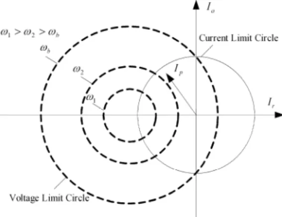
(Ulim ω)2≥(ψpm−LrIr)2+(LaIa)2 (7) where RIa is negligible compared to XrIr.
Due to that the maximum stator current is limited by the inverter current and the thermal rating of the motor, the phase current limitation equation is given by,
2 2 2
lim Ir Ia
I ≥ + (8) Fig. 5 shows the voltage limit circle and the current limit circle in the field weakening region. Lr =La due to the surface PM structure, so the voltage limit circle is curves is a circle. ωb is the corner speed, ω1>ω2>ωb is the speed of the motor.
If the motor speed ωr is below corner speed ωb, γ =0
=0
Ir and Ia=Ia_command. The output torque can be calculated
as Te=(3p ω)EpIp. If ωr is above ωb, Ir, Ir and γ can be expressed as,
⎥⎥
⎦
⎤
⎢⎢
⎣
⎡ Ψ
Ψ − Ψ −
⎟⎟⎠
⎞
⎜⎜⎝
− ⎛
=
r pm pm r pm
r s
r L
I L L
I U lim2
2
lim 1
2 1
ω (9)
( ) ( )lim 2 r 2
a I I
I = − (10)
(Ir Ia)
arctan
γ = (11) The output torque can be expressed as,
(3 ω) p pcosγ
e p E I
T = (12) Fig. 6 shows the diagram of control system.
Figure 4. Scalar control diagram.
Figure 5. Voltage limit circle and current limit circle in the scalar control.
Figure 6. Scalar control block diagram.
IV. RESULTS
Based on the data of a practical DS-PMBL motor as listed in Table 1, the performance of the proposed motor drive can be assessed. Firstly, the mesh diagram of the TS-FEM and the resulting magnetic field distribution at full load are shown in Fig. 7. Then, the torque-speed capability of the motor drive is simulated as shown in Fig. 8(a), which covers both the constant-torque operation (0-400 rpm) and the constant-power operation (400-1000 rpm). The corresponding current commands Ia* and Ir* are depicted in Fig. 8(b), which indicates that they online change with the speed to achieve the desired operations.
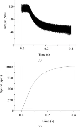
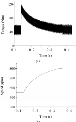
To assess the effectiveness of the proposed scalar control, three typical transient responses are analyzed. Firstly, Fig. 9 shows the startup transients when the motor drive is subjected to the rated load torque of 48 Nm. It verifies that the motor drive can quickly reach the top speed of 1000 rpm within 0.4 s. Secondly, Fig. 10 shows the transient responses when the rated load torque is suddenly applied at 1000 rpm. It verifies that the scalar control can swiftly react so that the resulting speed change is insignificant. Thirdly, Fig. 11 shows the transient responses when the speed command is suddenly changed from 500 rpm to 1000 rpm at the rated load torque. It further verifies that the motor drive can quickly track the commanded speed.
Fig. 12 shows the simulated torque-speed capabilities covering both the constant torque operation and the flux weakening operation. It can be seen that with the use of scalar control, the motor speed can be extended to three times the base speed. Also, as compared with the speed ranges using the conventional brushless AC (BLAC) control and brushless DC (BLDC) control, the speed range using the proposed scalar control is much wider. Moreover, the DS-PMBL motor drive is prototyped for experimentation, as shown in Fig. 13. Both the simulated and measured transient responses at startup under no load are shown in Fig. 14. The agreement is very good, which verifies the validity of the proposed control and the accuracy of the proposed analysis.
(a) (b)
Figure 7. Magnetic field analysis using TS-FEM. (a) Mesh diagram. (b) Magnetic field distribution at full-load.
(a)
(b)
Figure 8. Motor drive performance. (a) Torque-speed capability. (b) Current commands.
(a)
(b)
Figure 9. Transient responses under startup at rated load torque. (a) Torque.
(b) Speed.
(a)
(b)
Figure 10. Transient responses under sudden load change from no-load to rated load torque. (a) Torque. (b) Speed.
(a)
(b)
Figure 11. Transient responses under sudden command change from 500 rpm to 1000 rpm at rated load torque. (a) Torque. (b) Speed.
Figure 12. Comparison of torque-speed capabilities.
Figure 13. Prototype of the proposed double-stator PMBL motor drive.
TABLE 1. Motor data.
Rated power 2 kW
Rated speed 400 rpm
Rated torque 48 Nm
Inner stator inside diameter 92 mm Inner stator outside diameter 165 mm
Outer stator inside diameter 191 mm Outer stator outside diameter 245 mm
Stack length 50 mm
Inner stator slot number 24 Outer stator slot number 24
Pole number 22
Figure 14. Transient speed responses at no-load startup. (a) Simulated. (b) Measured (170 rpm/div, 100 ms/div).
V. CONCLUSIONS
In this paper, the transient performance of the DS-PMBL motor drive with scalar control has been analyzed by using the TS-FEM. The key is to incorporate the scalar control strategy into the field-circuit-torque equations of the TS-FEM. The simulation results have confirmed that the DS-PMBL motor drive can employ simple scalar control to provide fast and accurate transient responses which used to be offered by complicated vector control. Moreover, the accuracy of the developed TS-FEM has been verified by experimentation.
REFERENCES
[1] C. C. Chan and K. T. Chau, Modern Electric Vehicle Technology.
Oxford: Oxford University Press, 2001.
[2] C. C. Chan and K. T. Chau, “An advanced permanent magnet motor drive system for battery-powered electric vehicles,” IEEE Transactions on Vehicular Technology, vol. 45, no. 1, pp. 180-188, Feb. 1996.
[3] C. C. Chan and K. T. Chau, “An overview of power electronics in electric vehicles,” IEEE Transactions on Industrial Electronics, vol. 44, no. 1, pp. 3-13, Feb. 1997.
[4] S. Z. Jiang, K. T. Chau and C. C. Chan, “Spectral analysis of a new six- phase pole-changing induction motor drive for electric vehicles,” IEEE Transactions on Industrial Electronics, vol. 50, no. 1, pp. 123-131, Feb.
2003.
[5] K. T. Chau, J. Z. Jiang, and Y. Wang, “A novel stator doubly fed doubly salient permanent magnet brushless machine,” IEEE Transactions on Magnetics, vol. 39, no. 5, pp. 3001-3003, Sep. 2003.
[6] K. T. Chau and C. C. Chan, “Emerging energy-efficient technologies for hybrid electric vehicles,” Proceedings of IEEE, vol. 95, no. 4, pp. 821- 835, Apr. 2007.
[7] K. T. Chau, C. C. Chan and C. Liu, “Overview of permanent-magnet brushless drives for electric and hybrid electric vehicles,” IEEE Transactions on Industrial Electronics, vol. 55, no. 6, pp. 2246-2257, Jun. 2008.
[8] Y. Fan and K. T. Chau, “Design, modeling, and analysis of a brushless doubly fed doubly salient machine for electric vehicles,” IEEE Trans.
Industry Applications, vol. 44, no. 3, pp. 727-734, May-Jun. 2008.
[9] C. C. Chan, K. T. Chau, J. Z. Jiang, W. Xia, M. Zhu and R. Zhang,
“Novel permanent magnet motor drives for electric vehicles,” IEEE Transactions on Industrial Electronics, vol. 43, no. 2, pp. 331-339, April 1996.
[10] J. Gan, K. T. Chau, C. C. Chan and J. Z. Jiang, “A new surface-inset permanent brushless DC motor drive for electric vehicles,” IEEE Transactions on Magnetics, vol. 36, no. 5, pp. 3810-3818, Sep. 2000.
[11] W. Cui, K. T. Chau, J. Z. Jiang and Y. Fan, “Design of a novel phase- decoupling permanent magnet brushless ac motor,” Journal of Applied Physics, vol. 97, no. 10, paper no. 10Q515, pp. 1-3, May 2005.
[12] M. Cheng, Y. Fan and K. T. Chau, “Design and analysis of a novel stator-doubly-fed doubly salient motor for electric vehicles,” Journal of Applied Physics, vol. 97, no. 10, paper no. 10Q508, pp. 1-3, May 2005.
[13] K. T. Chau, W. Cui, J. Z. Jiang and Z. Wang, “Design of permanent magnet brushless motors with asymmetric air gap for electric vehicles,”
Journal of Applied Physics, vol. 99, no. 8, paper no. 80R322, pp. 1-3, Apr. 2006.
[14] K. T. Chau, D. Zhang, J. Z. Jiang, C. Liu and Y. J. Zhang, “Design of a magnetic-geared outer-rotor permanent-magnet brushless motor for electric vehicles,” IEEE Transactions on Magnetics, vol. 43, no. 6, pp.
2504-2506, June 2007.
[15] Z. Q. Zhu and D. Howe, “Electrical machines and drives for electric, hybrid and fuel cell vehicles,” Proceedings of IEEE, vol. 95, no. 4, pp.
746-765, Apr. 2007.
[16] C. Yu, K. T. Chau, X. Liu and J. Z. Jiang, “A flux-mnemonic permanent magnet brushless motor for electric vehicles,” Journal of Applied
[17] F. Chai, S. Cui and S. Cheng, “Study of a novel double-stator permanent-magnet electric machine,” Proceedings of IEEE Electric Machines and Drives Conference, vol. 3, Jun. 2003, pp. 1375−1378.
[18] F. Chai, S. Cui and S. Cheng, “Performance analysis of double-stator starter generator for the hybrid electric vehicle,” IEEE Transactions on Magnetics, vol. 41, no. 1, pp. 484-487, 2005.
[19] S. Niu, K. T. Chau and J. Z. Jiang, “Analysis of eddy-current loss in a double-stator cup-rotor PM machine,” IEEE Transactions on Magnetics, vol. 44, no. 11, pp. 4401-4404, Nov. 2008.
[20] S. Niu, K. T. Chau and C. Yu, “Quantitative comparison of double-stator and traditional permanent magnet brushless machines,” Journal of Applied Physics, vol. 105, no. 7, paper no. 07F105, pp. 1-3, Apr. 2009.
[21] Y. Wang, K.T. Chau, C.C. Chan and J.Z. Jiang, “Transient analysis of a new outer-rotor permanent-magnet brushless DC drive using circuit- field-torque time-stepping finite element method,” IEEE Transactions on Magnetics, vol. 38, no. 2, pp. 1297-1300, 2002.
[22] W. N. Fu, S. L. Ho, H. L. Li and H. C. Wong, “An improved nodal method for circuit and multi-slice magnetic field coupled finite element analysis,” Electric Power Components and Systems, vol. 32, no. 7, pp.
671-689, July 2004.
[23] K. T. Chau, D. Zhang, J. Z. Jiang and L. Jian, “Transient analysis of coaxial magnetic gears using finite element comodeling,” Journal of Applied Physics, vol. 103, no. 7, paper no. 07F101, pp. 1-3, April 2008.
[24] Y. Gong, W. Cui, K. T. Chau, C. Yu, and Y. Zhang, “Numerical analysis of magnetization in a mnemonic motor using time stepping finite element method coupled with Preisach theory,” IEEE Int. Electric Machines and Drives Conf., Miami, USA, pp. 839-844, May 2009.
[25] W. Cui, K.T. Chau, J.Z. Jiang, Y. Fan and Z. Wang, “Scalar control of a new phase-decoupling permanent magnet synchronous motor for servo applications,” Proceedings of IEEE Industry Applications Society Annual Meeting, Hong Kong, China, pp. 1762-1769, October 2005.
[26] D. Ishak, Z. Q. Zhu and D. Howe, “Eddy-current loss in the rotor magnets of permanent-magnet brushless machines having a fractional number of slots per pole,” IEEE Transactions on Magnetics, vol. 41, no.
9, pp. 2462-2469, Sep. 2005.
[27] D. Ishak, Z. Q. Zhu and D. Howe, “Comparison of PM brushless motors, having either all teeth of alternate teeth wound,” IEEE Transactions on Energy Conversion, vol. 21, no. 1, pp.95-103, Mar. 2006.
[28] S. Niu, K. T. Chau, J. Z. Jiang and C. Liu, “Design and control of a new double-stator cup-rotor permanent-magnet machine for wind power generation,” IEEE Transactions on Magnetics, vol. 43, no. 6, pp. 2501- 2503, Jun. 2007.
[29] A. M. EL-Refaie, T. M. Jahns and D. W. Novotny, “Analysis of surface permanent magnet machines with fractional-slot concentrated windings,” IEEE Transactions on Energy Conversion, vol. 21, no. 1, pp.
34-43, Mar. 2008.
[30] Z. Q. Zhu and D. Howe, “Influence of design parameters on cogging torque in permanent magnet machines,” IEEE Transaction on Energy Conversion, vol. 15, no. 4, pp. 407-412, Dec. 2000.
[31] Z. Q. Zhu, S. Ruanglsinchaiwanich, N. Schofield and D. Howe,
“Reduction of cogging torque in interior-Magnet brushless machines,”
IEEE Trans. on Magnetics, vol. 39, no. 5, pp. 3238-3240, Sept. 2003.
[32] D. Zhang, K. T. Chau, S. Niu and J. Z. Jiang, “Design and analysis of a double-stator cup-rotor PM integrated-starter-generator,” Proceedings of IEEE Industry Applications Society Annual Meeting, Tampa, Florida, USA, vol. 1, pp. 20-26, Oct. 2006.
[33] D. Zhang, S. Niu, K.T. Chau, J.Z. Jiang and Y. Gong, “Design and analysis of a double-stator cup-rotor directly driven permanent magnet wind power generator,” Proceedings of CES/IEEE Power Electronics and Motion Control Conference, Shanghai, China, pp. 1-5. Aug. 2006.
[34] S. Niu, K. T. Chau, D. Zhang, J. Z. Jiang and Z. Wang, “Design and control of a double-stator permanent-magnet motor drive for electric vehicles, ” Proceedings of IEEE Industry Applications Society Annual Meeting, New Orleans, USA, pp. 1293-1300, Sep. 2007.
[35] S. Niu, K. T. Chau and J. Z. Jiang “A permanent-magnet double-stator integrated-starter-generator for hybrid electric vehicles,” Proceedings of IEEE Vehicle Power and Propulsion Conference, Harbin, China, paper