ABB
ACS 1000 Medium Voltage Drives
315 – 5000 kW 400 – 6200 hp
Commissioning Manual
www.PLCworld.cn
www.91HMI.com
www.PLCworld.cn
ABB
ABB reserves all rights to this document, also in the event of patent issue or registration of any other industrial property protection right. Misuse, in particular duplication and forwarding to third parties, is not permitted. This document has been checked with due care and attention. However, should the user find any errors, these should be reported to ABB. ABB aims to maintain the most modern standard, therefore, entries in this manual may differ from the actual product.
www.PLCworld.cn
www.91HMI.com
www.PLCworld.cn
ABB
Table of Contents
Chapter 1 - Overview ...5
1.1. Safety... 5
1.2. Scope of Commissioning ... 5
1.3. Reports ... 6
1.4. Related Documents and Parameter References ... 6
1.5. Tools ... 6
Chapter 2 - Precommissioning Check List ...7
2.1. Office Preparations ... 7
2.2. Scope of Delivery... 8
2.3. Pre-Conditions for Commissioning ... 8
Chapter 3 - Inspection of Installation ...11
3.1. MCB... 11
3.2. Transformer (ACS 1000i: N.A.)... 11
3.3. Converter Room ... 12
3.4. Converter ... 13
3.5. Ground Connections... 14
3.6. Motor...14
Chapter 4 - Safety ...15
Chapter 5 - Connecting Auxiliary Supply to the Converter ...17
5.1. EPS Auxiliary Power Supply... 17
5.2. Phoenix Auxiliary Power Supply ... 18
5.3. Checking Of Auxiliary Backup Batteries ... 21
Chapter 6 - Commissioning of the Cooling System...23
6.1. Water-Cooled ACS 1000 ... 23
6.1.1. Checking the Internal and External Cooling Circuits ... 23
6.1.2. Filling Up the Internal Cooling Circuit ... 24
6.1.3. Functional Test of the Redundant Fan ... 24
6.2. Air-Cooled ACS 1000 and ACS 1000i ... 24
Chapter 7 - Insulation Resistance Measurements ...27
7.1. Preparations ... 27
7.2. External MCB... 27
7.3. Internal MCB (only ACS 1000i)... 28
7.4. Transformer ... 28
www.PLCworld.cn
www.91HMI.com
www.PLCworld.cn
Chapter 1 - Overview
ABB
7.7. Motor...35
7.8. Power Cables...36
Chapter 8 - Preparing the System ... 37
8.1. MCB and Protection Relay...37
8.2. Transformer ...37
8.3. Converter ...38
8.3.1. Standard Hardware ...38
8.3.2. Optional Hardware ...40
8.3.3. Customer Parameters ...40
8.3.4. Motor Parameters in Group 99 And 112 ...40
8.3.5. Testing of the MCB Control and the Tripping Loop...43
8.3.6. Testing of I/O’s...45
8.3.7. Testing of Fieldbus-Communication ...45
8.4. Motor...45
Chapter 9 - Energizing, First Start and Load Test ... 47
9.1. Energizing the Converter ...47
9.2. First Start ...50
9.3. Load Test ...51
9.4. Testing of Ride Through and Auto Restart Functions ...51
9.4.1. Main Power Ride Through ...51
9.4.2. Auxiliary Power Ride Through ...52
9.4.3. Auto Restart ...53
Chapter 10 - Final Work ... 55
10.1. Spare Parts ...55
10.2. Customer Training ...55
10.3. Parameter Backup ...55
10.3.1. Saving Parameters and System Software using DriveWindow...56
10.3.2. Saving Parameters and System Software using DriveDebug...59
10.4. Customer Approval ...63
10.5. Customer Documentation ...63
10.6. Documentation and Back-up Copies for Supportline ...63
10.6.1. Supportline Contact Information ...64
www.PLCworld.cn
www.91HMI.com
www.PLCworld.cn
Chapter 1 - Overview
The purpose of the manual is to assist in commissioning the ACS 1000 frequency converter. It includes necessary instructions, practical hints and references to related documentation to successfully commission the converter and the related equipment as needed for the application.
NOTICE!
Commissioning of the converter may only be carried out by personnel who have been certified at “expert” or “master” level by the Product Responsible Unit.
1.1. Safety
The safety instructions in this manual, in the User’s Manual and the local safety regulations must be observed to maintain safety to all those involved in commissioning the drive system.
DANGER!
Working on energized equipment can be a life hazard.
Mechanical forces, electric shock and burn can cause severe injuries or death.
Safety related work practices must be followed at all times.
Take appropriate measures when working on the drive system.
1.2. Scope of Commissioning
Normally, the commissioning engineer is only responsible for the
converter. If agreed by contract, the commissioning engineer can take on the commissioning of:
• Motor,
• Transformer,
• MCB,
• Protection relays,
• External devises (actuators, sensors etc.).
www.PLCworld.cn
www.91HMI.com
www.PLCworld.cn
Chapter 1 - Overview
ABB
1.3. Reports
During commissioning, the Commissioning Report and the Field Service Report and must be filled in. Templates of the documents are available on the MV AC Drives Portal.
1.4. Related Documents and Parameter References
The following manuals and specifications provide information on the drive equipment:
• ACS 1000 User’s Manual,
• WCU Operation and Maintenance Manual,
• Signal and Parameter Table,
• Main Circuit Breaker Specification and Application Note,
• Tripping Loop Application Note,
• Power Cable Specification,
• Main Transformer Specification,
• Motor Specification,
• ACS 1000 Service and Maintenance Manual.
When third-party equipment is included in the scope of commissioning see also:
• Main circuit breaker manual,
• Transformer manual,
• Motor manual.
1.5. Tools
• Toolbox with normal tools like screwdrivers, spanners etc.
• Torque spanner 10 - 75 Nm for hexagon head screws M6 to M12
• Personal computer with NDPA-02 PCMCIA-card, NDPC-12 optical transmitter / receiver, optical fiber cables and DriveWindows or DriveDebug
• Multimeter with test wires and clips, for example Fluke 87
• 5 kV Megger, for example AVO BM11D
• Water pump equipped with hoses and ISO-R½ female connector, for example Wolfcraft 2200 3000 L/H (PartsOnline code 09811402)
www.PLCworld.cn
www.91HMI.com
www.PLCworld.cn
Chapter 2 - Precommissioning Check List
2.1. Office Preparations
For an efficient commissioning, make sure that the following items are completed before travelling to site:
• Copy of field service report
• Copy of commissioning report
• Copy of converter documentation
• Information about the scope of delivery
• Information about SW and EPLD updates 1 and 3
• Special tuning instructions for converter 1
• Information on possible converter upgrades 1
• Setting values for motor parameters (equivalent circuit of the motor)
• Commissioning program (to be agreed with customer)
• Needed tools 2
• Suitable megger for insulation test 2
• Digital camera
• (Spare parts for commissioning)
1 Contact MV AC Supportline for information, see chapter 10.6.1 Supportline Contact information
2 See chapter 1.5 Tools
3 Preprogrammed EPLD’s have to be ordered from PartsOnline,
www.PLCworld.cn
www.91HMI.com
www.PLCworld.cn
Chapter 2 - Precommissioning Check List
ABB
2.2. Scope of Delivery
After receiving the converter and related equipment, the customer is asked to check all items against the bill of material and for shipping damages. Missing parts should be reported immediately to the carrier and the project responsible ABB organization. All claims for damage should be made to the carrier and ABB should be notified.
To avoid unnecessary delay of the commissioning, the commissioning engineer must assure himself that the equipment is complete and intact.
It is recommended practice to photograph damaged equipment and send the photographs to ABB and the carrier.
2.3. Pre-Conditions for Commissioning
In order to ensure an uncomplicated and fast commissioning, it is important that the converter and associated equipment are ready for commissioning. Reviewing and completing the items in the below list before the commissioning engineer arrives on site will help to achieve this.
1. Mechanical Installation of the Converter
• Converter is securely fixed to the floor
• Customer side raw water piping is completed and the pipes are connected to the converter
• Raw water supply is ready
2. Electrical Installation of the Converter
• All control cables going into the converter are connected, appropriately labelled and the customer side connections are completed
• Types and cross sections of control cables are suitable for the signal type and signal level
• Types and cross section of power cables are selected according to the “ABB power cable specification”
• Ground cable of converter is tightened on both ends
• Transformer and motor cables are not fastened at both ends (cables and converter must be meggered before connection)
www.PLCworld.cn
www.91HMI.com
www.PLCworld.cn
3. Main Circuit Breaker (MCB)
• The MCB is selected as per “ABB MCB specification”
• High voltage power connections are completed
• The MCB is ready to be tested with the converter
• The MCB protection relay settings are set and tested
• Safety devices (door locks etc.) are tested and in operation
4. Converter Transformer
• Grounding is completed
• Transformer auxiliaries (dehydrating breathers, cooling, protection devices) are ready
• Safety devices (door looks etc.) are tested and in operation
4. Motor
• Motor is installed, aligned and alignment protocol is available
• Grounding is completed
• Motor auxiliaries (bearing lubrication, space heater, cooling etc.) are ready
5. Megger Tests
• All power cables to converter transformer, between converter transformer and converter and between converter and motor are meggered and the measured values are within the required limits
• Test report of the megger test is available
If the test is carried out by the converter commissioning engineer, one additional day per converter-motor combination needs to be reserved. After the test, the mains cables can be
www.PLCworld.cn
www.91HMI.com
www.PLCworld.cn
Chapter 2 - Precommissioning Check List
ABB
6. Power
• Medium voltage is available for start-up of the converter
• Low voltage auxiliary power is available for start-up of the converter
7. Miscellaneous
• Sufficient number and correct type of spare parts are available
• Sufficient quantity of deionised water is available
• Air conditioning of drive room is ready for load run of converter
• Optional equipment (chiller unit etc.) is ready
www.PLCworld.cn
www.91HMI.com
www.PLCworld.cn
Chapter 3 - Inspection of Installation
In order to achieve a trouble-free commissioning, it is mandatory that the installation, including third-party equipment, is inspected.
The status of the installation is checked and it is verified that converter and related equipment are as specified for the application and have been installed according to the installation instructions and the applicable safety regulations.
Checking the installation is performed with the guidance of the
Commissioning Report. Equipment data asked for in the report must be obtained and noted in the corresponding sections of the report.
If further information on the equipment is required, the applicable documentation of the manufacturers should be consulted.
3.1. MCB
Check that the main circuit breaker is installed properly according to the local requirements and according to the instructions in the MCB
documentation. Pay special attention to the following:
• Ambient conditions,
• MCB power circuit connections,
• MCB grounding connections,
• MCB auxiliary voltage supply,
• Interface cabling between the MCB and the ACS 1000,
• Prevention of local control.
The local control of the MCB must be inhibited; all external controls to the MCB must go through the ACS 1000.
ACS 1000i: N.A. in case the MCB is installed in the converter.
3.2. Transformer (ACS 1000i: N.A.)
Check that the transformer is installed properly according to local requirements and according to the instructions in the transformer documentation. Pay special attention to:
• Ambient conditions,
• Transformer power circuit connections,
www.PLCworld.cn
www.91HMI.com
www.PLCworld.cn
Chapter 3 - Inspection of Installation
ABB
• Cables and busbars must have sufficient cross-sections in accordance with load current,
• Sharp bends in high-voltage conductors must be avoided,
• Minimum clearances between phase-to-phase and phase-to-earth parts must always be observed (this includes also the distances from cables to windings),
• All connections must be tight and mechanically secure, it is recommended to use a torque-wrench when tightening bolts for electrical connections (see Table 3-1),
Table 3-1 Recommended tightening torques for different bolt sizes
Bolt size Tightening torque
M6 6…9 Nm
M8 15…22 Nm
M10 30…44 Nm
M12 50…75 Nm
M16 120…190 Nm
• Transformer grounding connections,
• Make sure that transformer secondary power circuit protective shield connections are made according to recommendations (both ends connected to ground),
• The transformer frame must be connected to the protective grounding system,
• Interface cabling between the transformer and the ACS 1000.
3.3. Converter Room
When inspecting the converter room, attention must be paid to the following:
• Building work must be finished in the converter room.
• The converter room must be clean (free of dust) and dry.
• Air filters must be in place.
• Air conditioning must be available latest when the converter will be operated continuously.
If the condition of the converter room hampers effective commissiong, the customer and the responsible ABB project engineer must be informed immediately.
Cleanness of the converter room should be checked several times during commissioning.
www.PLCworld.cn
www.91HMI.com
www.PLCworld.cn
3.4. Converter
The inspection includes the mechanical and electrical installation of the converter. By visually checking the converter, the commissioning engineer obtains an overview of the condition of the converter and can react in time if corrections have to be made.
Useful information on the requirements for the installation site is written in the User’s Manual of the converter, Chapter 3 - Mechanical Installation and Appendix C – Mechanical Drawings.
If the installation of the converter has not been carried out as required or the condition of the converter hampers effective commissiong, the customer and the responsible ABB project engineer must be informed immediately.
When inspecting the converter, the checklist below can be used as a guide. Depending on the configuration of the converter and applicable options, there might be less or more check items. Always see supplied parts list, mechanical and electrical drawings for reference.
Check List
• Installation and damages of components.
• Cable openings should be closed to avoid dust entering into the cabinets.
• Foreign parts, dust and moisture must not be present in the converter cabinets.
It is very important that there is no dust and moisture inside the cabinets. Dust and moisture weaken the busbar insulation. Dust tends to build up on air-cooling elements, thus impairing cooling.
• Converter doors must open and close easily.
If the doors cannot be opened and closed properly, the alignment of the converter must be checked and corrected.
• Floor fixings must be mounted.
The mounting holes are indicated in Appendix C- Layout Drawing in the User’s Manual of the converter.
• Cooling water connections must be made.
Information on the flange sizes or project specific features are shown in Appendix C- Layout Drawing in the User’s Manual of the converter.
• Termination and routing of power cables.
All cable connections between converter and transformer and between converter and motor are shown in Appendix D – Electrical Drawings in the User’s Manual of the converter. Project specific cable entries are indicated in Appendix C – Mechanical Drawings in the
www.PLCworld.cn
www.91HMI.com
www.PLCworld.cn
Chapter 3 - Inspection of Installation
ABB
IMPORTANT!
Power cables must not be connected at the converter before the insulation resistance of the converter and the motor have been measured.
3.5. Ground Connections
Ground connections must be carried out carefully to prevent that high potentials will occur in any parts, which can be touched easily.
Inspection of ground connections includes the following:
• The converter must be connected to the ground system of the factory (system ground).
• The shields of all power cables must be connected to the ground busbar.
• The cross section of the cable shields must be in accordance with the Power Cable Specification.
3.6. Motor
The motor area must be cleaned so that it is safe to run the motor. All waste that can come in contact with the shaft or the cooling air inlets must be removed.
The motor installation includes the piping of lubrication and water-cooling system and the alignment of the motor. An alignment protocol must be available on site.
The motor frame must be connected to the ground network of the plant.
For more details see instructions of the motor manufacturer.
www.PLCworld.cn
www.91HMI.com
www.PLCworld.cn
Chapter 4 - Safety
Before power is applied to the converter, it must be checked that all covers are back in place so that voltage-carrying parts cannot be touched accidentally. Interlocks, which prevent that medium and high voltage units can be accessed accidentally, must be in operation.
• Protection covers inside the converter must be refitted.
If covers have to be removed for measuring purposes, appropriate safety signs and temporary barriers must be installed and personnel involved in the commissioning must be informed.
• Cabinet door locks must be checked.
The doors should be kept closed whenever possible. This also helps to keep the cabinets clean.
Door keys should only be given to persons who take part in the commissioning.
• All openings of the motor must be closed and shaft covers must be installed.
The area around the motor must be cordoned off to prevent accidents during the uncoupled motor tests.
• All covers of power cable terminals or terminal boxes in the converter, motor, transformer and MCB must be closed.
• Open transformer and motor cable ends must be tied together and properly grounded.
www.PLCworld.cn
www.91HMI.com
www.PLCworld.cn
Chapter 4 - Safety
ABB
www.PLCworld.cn
www.91HMI.com
www.PLCworld.cn
Chapter 5 - Connecting Auxiliary Supply to the Converter
For the next steps, auxiliary voltage is needed.
The auxiliary power supply can be made according to two different concepts in the ACS 1000.
• With EPS-board (old concept).
• With Phoenix power supply modules (new concept).
5.1. EPS Auxiliary Power Supply
When the ACS 1000 is equipped with EPS-board(s), it is supplied with one common 3-phase 400, 480 or 575 VAC (other voltages as
engineered option) auxiliary supply for the control electronics and the cooling system.
Procedure for switching on the auxiliary voltage:
4 Make sure that the protection switches Q1, Q11, Q12, Q13, Q14 and all optional switches are off.
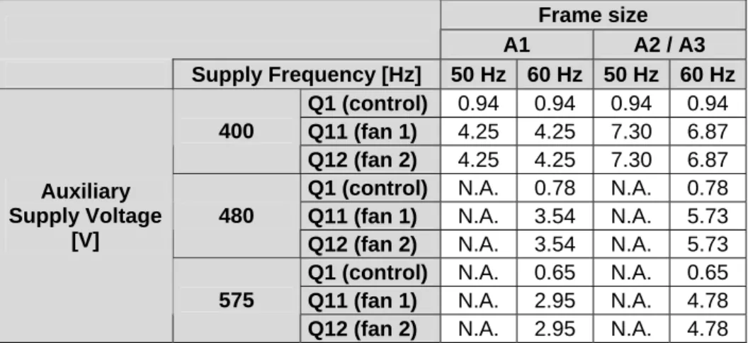
5 Check the settings of the protection switches Q1, Q11, Q12, Q13 and Q14 (see Table 5-1 and Table 5-2).
The settings for all other switches are project specific.
Table 5-1 Settings for protection switches (ACS 1000A)
Frame size
A1 A2 / A3
Supply Frequency [Hz] 50 Hz 60 Hz 50 Hz 60 Hz Q1 (control) 0.94 0.94 0.94 0.94 Q11 (fan 1) 4.25 4.25 7.30 6.87 400
Q12 (fan 2) 4.25 4.25 7.30 6.87 Q1 (control) N.A. 0.78 N.A. 0.78 Q11 (fan 1) N.A. 3.54 N.A. 5.73 480
Q12 (fan 2) N.A. 3.54 N.A. 5.73 Q1 (control) N.A. 0.65 N.A. 0.65 Q11 (fan 1) N.A. 2.95 N.A. 4.78 Auxiliary
Supply Voltage [V]
575
Q12 (fan 2) N.A. 2.95 N.A. 4.78
www.PLCworld.cn
www.91HMI.com
www.PLCworld.cn
Chapter 5 - Connecting Auxiliary Supply to the Converter
ABB
Table 5-2 Settings for protection switches (ACS 1000W) Frame size
W1 W2 / W3
Supply Frequency [Hz] 50 Hz 60 Hz 50 Hz 60 Hz Q1 (control) 1.62 1.62 1.62 1.62 Q11 (pump 1) 4.10 4.50 4.10 4.50 Q12 (pump 2) 4.10 4.50 4.10 4.50 Q13 (fan 1) 2.61 3.10 2.61 3.10 400
Q14 (fan 2) 2.61 3.10 2.61 3.10 Q1 (control) N.A. 1.35 N.A 1.35 Q11 (pump 1) N.A 4.20 N.A 4.20 Q12 (pump 2) N.A 4.20 N.A 4.20 Q13 (fan 1) N.A 2.59 N.A 2.59 480
Q14 (fan 2) N.A 2.59 N.A 2.59 Q1 (control) N.A 1.12 N.A 1.12 Q11 (pump 1) N.A 3.50 N.A 3.50 Q12 (pump 2) N.A 3.50 N.A 3.50 Q13 (fan 1) N.A 2.16 N.A 2.16 Auxiliary
Supply Voltage [V]
575
Q14 (fan 2) N.A 2.16 N.A 2.16
6 Check that the voltage selection in the 3-phase auxiliary transformer T1 is correct selected for each phase.
7 Check that the 3-phase auxiliary voltage supplied from customer side is within tolerance and write down the value (can be measured from terminal X10).
8 Switch on the auxiliary voltage to the converter control electronics with the circuit breaker Q1.
9 Check that the 24 VAC auxiliary voltages at the transformer secondary are correct in all three phases.
10 Check that the 32 VAC auxiliary voltages at the transformer secondary are correct in all three phases.
11 Check that the output voltage of the EPS-board(s) are ok (27 VDC, 27 VAC and +/- 20 VDC).
12 Check that both the yellow and green LED’s on all subprints on both GUSP-units (Gate Unit power Supply) are on.
5.2. Phoenix Auxiliary Power Supply
When the ACS 1000 is equipped with Phoenix auxiliary power supplies, the supply can be arranged different ways. The exact configuration can be checked from position 18 in the typecode.
A External 3-phase supply and external 1-phase safe line for control.
B External 3-phase supply and internal UPS.
www.PLCworld.cn
www.91HMI.com
www.PLCworld.cn
D Internal 3-phase supply and external 1-phase supply (no safe line) for control and internal back-up battery.
E Internal 3-phase supply and internal 1-phase supply for control and internal back-up battery.
F Only available for 575 VAC 3-phase supply.
IMPORTANT!
Configurations A and B are only available for 400 VAC / 480 VAC 3- phase supply.
Configurations D and E are only available for ACS 1000i with 60Hz supply network.
Procedure for switching on the auxiliary voltage:
1 Make sure that the switch S5001 (in configration E only) is in position 1 (i.e. the external commissioning auxiliary power supply is used).
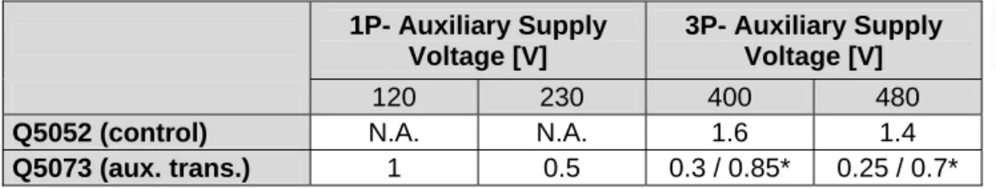
2 Make sure that the protection switches Q5051, Q5052, Q5073, Q5021, Q5022, Q5023, Q5024 and all optional switches are off.
3 Check the settings of all protection switches (see Table 5-3, Table 5-4, Table 5-5 and Table 5-6).
Table 5-3 Settings for protection switches (control hardware supply) 1P- Auxiliary Supply
Voltage [V]
3P- Auxiliary Supply Voltage [V]
120 230 400 480
Q5052 (control) N.A. N.A. 1.6 1.4
Q5073 (aux. trans.) 1 0.5 0.3 / 0.85* 0.25 / 0.7*
*if ACS 1000i with intergrated contactor and configuration B Table 5-4 Settings for protection switches (ACS 1000A)
Frame size
A1 A2 / A3
Supply Frequency (Hz) 50 Hz 60 Hz 50 Hz 60 Hz Q5021 (fan 1) 4.25 4.25 7.30 6.87 400 Q5023 (fan 2) 4.25 4.25 7.30 6.87
Q5021 (fan 1) N.A. 3.54 N.A. 5.73 480 Q5023 (fan 2) N.A. 3.54 N.A. 5.73
Q5021 (fan 1) N.A. 2.95 N.A. 4.78 Auxiliary Supply
Voltage [V]
575 Q5023 (fan 2) N.A. 2.95 N.A. 4.78
www.PLCworld.cn
www.91HMI.com
www.PLCworld.cn
Chapter 5 - Connecting Auxiliary Supply to the Converter
ABB
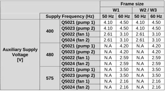
Table 5-5 Settings for protection switches (ACS 1000W)
Frame size
W1 W2 / W3
Supply Frequency (Hz) 50 Hz 60 Hz 50 Hz 60 Hz Q5021 (pump 1) 4.10 4.50 4.10 4.50 Q5023 (pump 2) 4.10 4.50 4.10 4.50 Q5022 (fan 1) 2.61 3.10 2.61 3.10 400
Q5024 (fan 2) 2.61 3.10 2.61 3.10 Q5021 (pump 1) N.A 4.20 N.A 4.20 Q5023 (pump 2) N.A 4.20 N.A 4.20 Q5022 (fan 1) N.A 2.59 N.A 2.59 480
Q5024 (fan 2) N.A 2.59 N.A 2.59 Q5021 (pump 1) N.A 3.50 N.A 3.50 Q5023 (pump 2) N.A 3.50 N.A 3.50 Q5022 (fan 1) N.A 2.16 N.A 2.16 Auxiliary Supply
Voltage [V]
575
Q5024 (fan 2) N.A 2.16 N.A 2.16
Table 5-6 Settings for protection switches (ACS 1000i)
Frame size
A1 A2 / A3
Supply Frequency (Hz) 50 Hz 60 Hz 50 Hz 60 Hz Q5021 (fan 1) 3.54 3.54 3.54 3.54 Q5022 (fan 2) 5.73 5.73 5.73 5.73 Q5023 (fan 3) 3.54 3.54 3.54 3.54 400
Q5024 (fan 4) 5.73 5.73 5.73 5.73 Q5021 (fan 1) N.A 3.54 N.A 3.54 Q5022 (fan 2) N.A 3.54 N.A 5.73 Q5023 (fan 3) N.A 3.54 N.A 3.54 Auxiliary Supply
Voltage [V]
480
Q5024 (fan 4) N.A 3.54 N.A 5.73
4 Check that the one-phase and / or three-phase auxiliary voltage supplied from customer side is within tolerance and write down the value, can be measured from.
• Terminals X11:1 and X11:2 in case of external 1- phase auxiliary power supply.
• Terminals X11:3 and X11:4 in case of internal 1- phase supply (only applicable in ACS 1000i).
• Terminals X10:1, X10:2 and X10:3 in case of internal (only applicable in ACS 1000i) or external 3-phase auxiliary power supply.
5 Check that the settings of the UPS modules are correct (if applicable).
• Battery Select: 7.2 Ah
• Tmax: 5 min
www.PLCworld.cn
www.91HMI.com
www.PLCworld.cn
IMPORTANT!
During commissioning the Battery Select switch on the UPS modules can be set to “Service”. In the service mode, the UPS module will not keep the control hardware supplyed from the backup batteries and thus rebooting of the converter is faster.
6 Switch on the auxiliary voltage to the control electronics with the circuit breakers Q5051 and / or Q5052 (see the drive specific wiring diagrams).
7 Check that the output voltages of the power supply modules are ok (27 VDC +/- 0.5 VDC), in case necessary tune the output voltage on each power supply.
8 Switch on the 24 VAC power supply with the circuit breaker Q5073 and measure the.
9 Check that both the yellow and green LED’s on all subprints on GUSP1 and GUSP2 (Gate Unit power Supply) are on.
5.3. Checking Of Auxiliary Backup Batteries
If it is more than 6 months from the dispatch of the converter from the factory in Switzerland, check the charging of the auxiliary backup batteries and check the function of the auxiliary ride-through function. If necessary replace the batteries with new ones.
IMPORTANT!
Auxiliary batteries are considered to be wear-and-tear-parts and cannot be replaced as warranty.
www.PLCworld.cn
www.91HMI.com
www.PLCworld.cn
Chapter 5 - Connecting Auxiliary Supply to the Converter
ABB
www.PLCworld.cn
www.91HMI.com
www.PLCworld.cn
Chapter 6 - Commissioning of the Cooling System
6.1. Water-Cooled ACS 1000
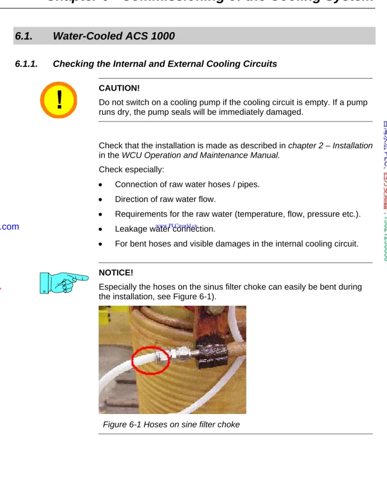
6.1.1. Checking the Internal and External Cooling Circuits
CAUTION!
Do not switch on a cooling pump if the cooling circuit is empty. If a pump runs dry, the pump seals will be immediately damaged.
Check that the installation is made as described in chapter 2 – Installation in the WCU Operation and Maintenance Manual.
Check especially:
• Connection of raw water hoses / pipes.
• Direction of raw water flow.
• Requirements for the raw water (temperature, flow, pressure etc.).
• Leakage water connection.
• For bent hoses and visible damages in the internal cooling circuit.
NOTICE!
Especially the hoses on the sinus filter choke can easily be bent during the installation, see Figure 6-1).
Figure 6-1 Hoses on sine filter choke
www.PLCworld.cn
www.91HMI.com
www.PLCworld.cn
Chapter 6 - Commissioning of the Cooling System
ABB
• Cleanness of the strainer Z1.
This should be checked again after some days of operation because during the first time of water flow possible loose particles and dirt from the water pipes should be flushed out and caught in the strainer.
6.1.2. Filling Up the Internal Cooling Circuit
Fill the internal cooling circuit according to the instructions in chapter 3 – Starting up the Cooling System in the WCU Operation and Maintenance Manual.
After filling up the internal cooling circuit, remember to:
• Vent (deaerate) the internal cooling pumps.
• Check the direction of internal water flow (check the direction of rotation of the pumps).
• Check the direction of rotation of the auxiliary cooling fans.
• Check the water level in the expansion vessel.
6.1.3. Functional Test of the Redundant Fan
In case the converter is equipped with redundant cooling fans, check the function according to the instruction below.
1 Start pump number 1, fan number 1 (standard fan inside cabinet) starts rotating, the air-flaps under the redundant fan should be closed and the air flaps under the internal fan should open.
2 Feel the air flow (how strong does the fan blow).
3 Switch off the motor circuit breaker of the standard fan, the redundant fan starts rotating, the air flaps under the redundant fan should open and the air flaps under the internal fan should close.
4 Feel the air flow of redundant fan, it should blow as strong as fan number 1.
5 In case the air flow is much weaker you have to change the direction of rotation of the redundant fan.
6.2. Air-Cooled ACS 1000 and ACS 1000i
• Check that the air exhaust box on top of the converter is assembled according to the instructions (ACS 1000i: N.A.).
• Check that all applicable fans installed on top of the converter are installed (only ACS 1000i).
• Check that the fan(s) are rotating smoothly and in the right direction.
• In case of redundant fans check that the installation of the fan box is made according to the instructions.
www.PLCworld.cn
www.91HMI.com
www.PLCworld.cn
• In case of redundant fans check that the air flap limiting device is functioning properly.
• Check and test the function of the installed differential pressure switches (see Table 6-1 and Table 6-2).
Table 6-1 Settings for differential pressure sensors (ACS 1000A)
Sensor B1 / B5261
(Fan Supervision)
B2 / B5824 (Filter Supervision)
Setting 150 Pa 280 Pa
Table 6-2 Settings for differential pressure sensors (ACS 1000i)
Sensor B5261
(Fan Gr. 1)
B5262 (Fan Gr. 2)
B5264 (Filter Sup.)
Setting 100 Pa 90 Pa
www.PLCworld.cn
www.91HMI.com
www.PLCworld.cn
Chapter 6 - Commissioning of the Cooling System
ABB
www.PLCworld.cn
www.91HMI.com
www.PLCworld.cn
Chapter 7 - Insulation Resistance Measurements
Before any of the components in the drive system can be energized, it must be assured that they are able to withstand the voltage stress. This can be verified by measuring the insulation resistance. If the measured insulation resistance value of the motor, transformer or converter is too low, the reason may be that insulators, windings etc. have moisture in them and it may be necessary to dry the windings.
It is advisable to compare the test results with the test reports from the supply factories.
The contractor or customer can make the insulation resistance
measurements on the supply transformer, cables and motor, in that case a signed test-protocol of all measurements must be attached to the commissioning report. A certified commissioning engineer must always make the insulation resistance measurement test on the ACS 1000.
7.1. Preparations
• Make sure that the Main Circuit Breaker is locked in test position (ACS 1000i: make sure that the external supply breaker is locked in test position).
• Disconnect the cables between the supply transformer and the converter and isolate them from ground and the frames of the transformer and the converter (ACS 1000i: disconnect the supply cables and isolate them from ground and the frames of the supply breaker and the converter).
• Disconnect the cables between the converter and the motor and isolate them from ground and the frames of the converter and the motor.
7.2. External MCB
The main circuit breaker is commissioned and the insulation tests are performed according to the documentation of the manufacturer. The signed MCB commissioning report must be received from the responsible person.
www.PLCworld.cn
www.91HMI.com
www.PLCworld.cn
Chapter 7 - Insulation Resistance Measurements
ABB
7.3. Internal MCB (only ACS 1000i)
All poles should be meggered against each other and against ground.
The absolute value depends on other equipment connected to the breaker but it should be higher than 1 MΩ per 1 kV.
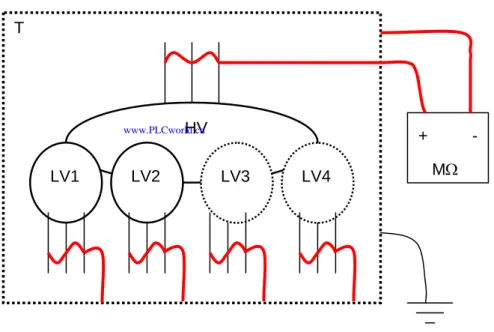
7.4. Transformer
The following procedure should be used for checking the insulation resistance measurement of the supply transformer (ACS 1000i: The internal transformer is tested together with the converter and it is not necessary to test it separately).
1 Short circuit all windings individually (HV, LV1 and LV2
andadditionally LV3 and LV4 in case of a 24-pulse transformer).
2 Connect all other windings than the one to be measured to ground (see Figure 7-1).
Figure 7-1 Example of meggering the HV-winding against ground HV
LV2 LV3 LV4
LV1 T
+ MΩ
-
3 Connect the megger between the winding to be measured and ground, the test voltage is 5 kVDC for 60 seconds.
www.PLCworld.cn
www.91HMI.com
www.PLCworld.cn
4 Repeat the measurement for the other windings, all individual windings should be measured against ground, the following measurements are needed:
• HV – T/E,
• LV1 – T/E,
• LV2 – T/E,
• LV3 – T/E (in case of 24-pulse transformer),
• LV4 – T/E (in case of 24-pulse transformer).
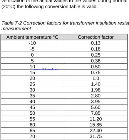
The insulation resistance should normally be several thousand MΩ, the value is however depending on temperature of the transformer. For verification of the actual values to the values during normal conditions (20°C) the following conversion table is valid.
Table 7-2 Correction factors for transformer insulation resistance measurement
Ambient temperature °C Correction factor
-10 0.13 -5 0.18
0 0.25 5 0.36 10 0.50 15 0.75 20 1.0 25 1.40 30 1.98 35 2.80 40 3.95 45 5.60 50 7.85 55 11.20 60 15.85 65 22.40 70 31.75 75 44.70
www.PLCworld.cn
www.91HMI.com
www.PLCworld.cn
Chapter 7 - Insulation Resistance Measurements
ABB
7.5. Converter (Standard Air- and Water-Cooled ACS 1000)
1 Connect all medium voltage input and output connections 1U1, 1V1, 1W1, 2U1, 2V1, 2W1, U2, V2, W2 (and 3U1, 3V1, 3W1, 4U1, 4V1 and 4W1 in case of a 24-pulse rectifier) together.
2 Connect the DC-capacitor terminals Plus, Minus and NP together (the easiest place is the terminals on the grounding switch).
3 Remove the DC-voltage measurement cables from the ADCVI- and OVVP-boards (terminals X2.1, X2.3 and X2.5) and make sure that the wires don’t touch the frame or the boards.
4 Remove the door center post in front of the inverter swing frame (only in water-cooled converters, see Figure 7-3).
5 Remove the ground-connection of resistor RN.
6 Remove the ground-connection of the star point of the output filter capacitors Cf.
7 Close the doors to the medium voltage cabinets of the converter.
8 Open the grounding switch.
9 Switch off the auxiliary voltage of the converter.
10 Connect the megger between the main connections (1U1, 1V1, 1W1, 2U1, 2V1, 2W1, U2, V2, W2) and ground.
11 Megger the converter main circuit against ground.
The test voltage should be 5000 VDC for 60 seconds. The measured insulation resistance must be higher than 10 Mohm in a water-cooled ACS 1000 and higher than 100 Mohm in an air-cooled ACS1000. In the water-cooled ACS 1000, the result is depending on the actual water conductivity of internal cooling water, if the conductivity is below 0,3 uS it is normally possible to get an acceptable result.
12 Discharge the measured circuit.
13 Close the grounding switch.
14 Switch on the auxiliary voltage of the converter.
15 Connect the ground-connection of resistor RN to ground.
16 Connect the ground-connection of the star point of the output filter capacitors to ground.
17 Connect the DC-voltage measurement cables to the ADCVI- and OVVP-boards (terminals X2.1, X2.3 and X2.5).
18 Take out all short circuit jumpers that were connected before the insulation resistance measurement.
19 Install the door center posts (in case applicable, see Figure 7-3).
www.PLCworld.cn
www.91HMI.com
www.PLCworld.cn
Figure 7-3 Door center posts
CAUTION!
Serious damage can be caused on the converter in case it is energized without removing all short-circuit-jumpers.
www.PLCworld.cn
www.91HMI.com
www.PLCworld.cn
Chapter 7 - Insulation Resistance Measurements
ABB
Ls1 Ls2
Lf Cf
Rdis1 Rdis2
Rsym
Vs1 Vs2
Cdc1 Cdc2
Ccl1 Ccl2
Rs1 Rs2
Vcl1 Vcl2
V1u V2u V3u V4u
V2Nu
V1Nu
V1v V2v V3v V4v
V2Nv
V1Nv
V1w V2w V3w V4w
V2Nw
V1Nw
Rpre1 Rpre2
Fs1 Fs2
Rr1 Cr1 Rr2Cr2
Rn
Fm RmCm
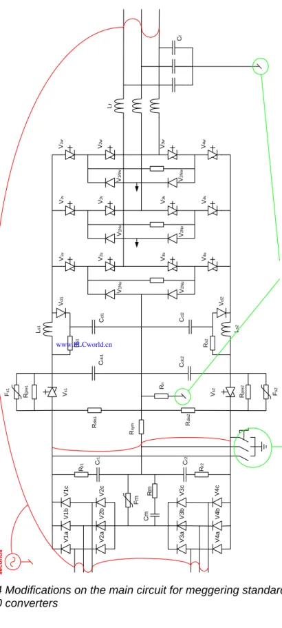
V1aV1cV1b V2aV2cV2b V3aV3cV3b V4aV4cV4b Disconnect: 1. The star point of the output filter 2. The ground connection on resistor RnOpen the grounding switch
5 KV / 60 seconds
Figure 7-4 Modifications on the main circuit for meggering standard ACS 1000 converters
www.PLCworld.cn
www.91HMI.com
www.PLCworld.cn
7.6. Converter (ACS 1000i)
1 Connect the medium voltage input and output connections U1, V1, W1, U2, V2 and W2 together (in the cable cabinet on the left side of the converter).
2 Close the MCB by jumpers (if applicable).
3 Short circuit all four 6-pulse rectifiers (AC and DC terminals) and connect them to the input and output connectors.
4 Connect the auxiliary windings of all transformers together and ground them.
5 Remove the ground-connection of resistor RN (input section).
6 Remove the ground-connection from the star point of the output filter capacitors Cf (input section).
7 Disconnect the surge arrestors from ground.
8 Remove the DC-voltage measurement cables from the ADCVI-, OVVP1- and OVVP2-boards (terminals X2.1, X2.3 and X2.5) and make sure that the wires don’t touch the frame of the converter or the board.
9 Open the grounding switch (manual unlocking).
10 Close the doors of the converter.
11 Switch off the auxiliary voltage of the converter.
12 Connect the megger between the main connections (1U, 1V, 1W, U2, V2, W2) and the ground.
13 Megger the converter main circuit against ground.
The test voltage should be 5000 VDC for 60 seconds. The measured insulation resistance must be higher than 100 Mohm.
14 Discharge the main circuit.
15 Close the grounding switch.
16 Switch on the auxiliary voltage of the converter.
17 Connect the ground-connection of resistor RN to ground.
18 Connect the surge arrestors to ground.
19 Connect the ground-connection of the star point of the output filter capacitors to ground.
20 Connect the DC-voltage measurement cables to the ADCVI-, OVVP1 and OVVP2-boards (terminals X2.1, X2.3 and X2.5).
21 Take out all short circuit jumpers that were connected before the insulation resistance measurement.
www.PLCworld.cn
www.91HMI.com
www.PLCworld.cn
Chapter 7 - Insulation Resistance Measurements
ABB
CAUTION!
Serious damage can be caused on the converter in case it is energized without removing all short-circuit-jumpers.
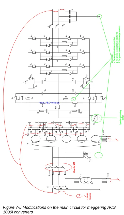
Figure 7-5 Modifications on the main circuit for meggering ACS 1000i converters
www.PLCworld.cn
www.91HMI.com
www.PLCworld.cn
7.7. Motor
1 The frame and the windings not being tested must be grounded during the insulation resistance measurement.
2 All resistance temperature detectors (RTD) must be grounded.
The insulation resistance of new motor is normally very high. A thumb rule can be that if the measured value is one decade or more lower than the value measured in the factory, check the winding for excess moisture or dirt. The test report contains the insulation resistance value measured in the factory.
If the motor star point is reachable, measure each phase separately as shown in Figure 7-6.
Figure 7-6 Insulation resistance measuring when star point is reachable (3 measuring values)
If the star point is not reachable, measure all phases together as shown in Figure 7-7.
M
Figure 7-7 Insulation resistance measuring when star point is not reachable (1 measuring value)
If the reading is too low, dry the motor windings according to instructions in the motor documentation.
www.PLCworld.cn
www.91HMI.com
www.PLCworld.cn
Chapter 7 - Insulation Resistance Measurements
ABB
7.8. Power Cables
Measure the insulation resistance of all power cables and write down the measured results. Measurements have to be made between all phases (all cables apart from each other) and between all cables and ground (all cables bound together at one end). Record the lowest value for each measurement.
www.PLCworld.cn
www.91HMI.com
www.PLCworld.cn
Chapter 8 - Preparing the System
Before the drive system components can be energized they must be checked and prepared for switching on the main voltage. When
inspecting each of the system components, follow the instructions given in the documentation for each of the components.
8.1. MCB and Protection Relay
Protection relays in the feeding switchgear must be tested, especially the relays of the converter transformer. The setting of these relays must be checked and compared with the project specific values. Relay test protocols must be available on site.
The correct operation of the MCB will be tested before the MCB is used to supply the main power to the converter. The test is performed with the main power supply disconnected from the MCB.
Information on the required control interface to the converter and on the breaking time of the circuit breaker can be obtained from the Main Circuit Breaker Specification and the Main Circuit Breaker Application Note.
• Check that the operational mechanisms of the MCB are working properly (WITHOUT MEDIUM VOLTAGE SUPPLY).
• Check that the MCB interlocking and locking facilities are working properly.
• Check that the MCB can be racked out properly.
• Check that the MCB cannot be operated locally.
8.2. Transformer
All checks and insulation measurements of transformers must be
performed according to the instructions of the transformer manufacturer.
Checking of the transformer includes the following:
• Rating plate values must correspond to the project data,
• Cleanness of transformer room and equipment,
• Thermal protective devices and other external measurement and protection devices,
• Oil quantity, in case of oil type transformer,
Oil quantity can be checked on the oil level gauge located on the oil
www.PLCworld.cn
www.91HMI.com
www.PLCworld.cn
Chapter 8 - Preparing the System
ABB
• Valves between transformer tank and radiator,
All valves must be in open position to allow free oil flow between tank and radiators,
• Condition of dehydrating breathers,
• Sense of rotation of fans and pumps (if applicable).
IMPORTANT!
The protectice devices from the supply transformer can be connected either to the ACS 1000 or to some other protection device. If they are not conncted to the ACS 1000, it is recommended to connect one common “Transformer trip signal” to the ACS 1000 tripping loop, connectors X300:7 and X300:8.
8.3. Converter
8.3.1. Standard Hardware
The following things must be checked before the ACS 1000 can be energized.
• Visually all medium voltage connections (busbars and cables).
• Visually all auxiliary supply cables.
• Visually all fibre optic cables.
• In case of water cooled ACS 1000, the centre post in font of the inverter must be installed (see Figure 7-3).
• In case of a water-cooled ACS 1000, the shipping brackets securing the swing frame must be removed.
• All semiconductors (IGCT’s and diodes) in the rectifier and the inverter must be measured with a Multimeter.
• The DIP-switches for configuring the analogue inputs are correct set (each IOEC-board has it’s own set of dip-switches).
All analogue inputs can be set to current or voltage range with dip switches (2 switches / analogue input), see Figure 8-1 and Figure 8-2.
www.PLCworld.cn
www.91HMI.com
www.PLCworld.cn
AI 20mA AI 10V ON
OFF
Figure 8-1 DIP Switch configuration for current-signal
AI 20mA AI 10V
ON
OFF
Figure 8-2 DIP Switch configuration for voltage-signal
In ACS 1000i the Pt100’s are connected directly to the IOEC-board, for this connection both dip-switches have to be set to OFF, see Figure 8-3.
AI 20mA AI 10V
OFF OFF
Figure 8-3 DIP Switch configuration for temperature measurement in ACS 1000i
• Calibration of analogue inputs.
Disconnect the terminals –X31 and –X32 on all IOEC-boards and set the following parameters to “YES” to perform the offset-calibration.
IOEC 1 and IOEC2: Parameter 13.01 Auto Offset Calib.
IOEC 3: Parameter 81.01 Auto Offset Calib.
IOEC 4: Parameter 86.01 Auto Offset Calib.
• Parameters for inverter air and transformer temperature measurement in ACS 1000i (see
www.PLCworld.cn
www.91HMI.com
www.PLCworld.cn
Chapter 8 - Preparing the System
ABB
Table 8-4 Settings for Analogue Inputs for temperature measurement in ACS 1000i
Parameter Setting
190.28 AI4 Filter IO1 1s
190.27 AI4 Minimum IO1 4mA/2V
190.25 AI4 HighValue IO1 10550
190.26 AI4 LowValue IO1 -13
8.3.2. Optional Hardware
• Check the supply voltage for the motor space heater and write down the value.
• Check the supply voltage for converter space heaters and write down the value.
• Check the function of all included options (motor space heater, converter space heater, motor cooling fan / pump etc.).
8.3.3. Customer Parameters
Set all customer specific parameters. For more information see the Signal and Parameter table.
IMPORTANT!
Different software-versions may have different parameters.
8.3.4. Motor Parameters in Group 99 And 112
• Calculate the motor parameters with the mot_par-Excel-table, either with the name plate data of the motor (see Figure 8-5) or with the equivalent circuit of the motor (see Figure 8-6).
To ensure that the motor parameters are calculated correctly, the mot_par-table from the loading package of the used software must be used.
• Check that the filter capacitance specified with the type code (cell B45) corresponds with the filter capacitance value in parameter 6.15 FilterCapacity and with the installed sine filter capacitance in the converter (check the name plates of the installed capacitors).
• Check that the filter inductance specified with the type code (cell B46) corresponds with the filter inductance value in parameter 6.14 FilterInductance and with the installed sine filter choke in the converter (check the name plate of the installed choke).
• Check that the filter resonance frequency (cell E70) is less than 380 Hz.
www.PLCworld.cn
www.91HMI.com
www.PLCworld.cn
If the calculated resonance frequency is higher than 380 Hz, check that the entered motor data and the entered sine filter inductance and capacitance are correct, if the calculated sine filter resonance
frequency is still too high, the sine filter configuration must be changed.
• Set the correct motor parameters in group 99.
• Set the correct motor parameters calculated with the mot_par-Excel- table in group 112, the group can be opened with the password 564.
IMPORTANT!
The sine filter damping parameters in group 112 (older software
versions) or group 115 (newer software versions) must not be modified, they are automatically set to the correct values by the software loading package.
www.PLCworld.cn
www.91HMI.com
www.PLCworld.cn
Chapter 8 - Preparing the System
ABB
Figure 8-5 Example of motor parameter calculation with the name plate data
www.PLCworld.cn
www.91HMI.com
www.PLCworld.cn
Figure 8-6 Example of motor parameter calculation with the motor equivalent circuit
8.3.5. Testing of the MCB Control and the Tripping Loop
Check the function of the MCB and the tripping loop without main voltage.
For more information see the following application notes:
• ACS 1000 Main Circuit Breaker Control
• ACS 1000 Tripping Loop
www.PLCworld.cn
www.91HMI.com
www.PLCworld.cn
Chapter 8 - Preparing the System
ABB
The test can be made according to the following procedure:
1 Make sure the MCB is in test-position.
2 Set all appropriate parameters for the MCB Control.
• 21.06 MCB On Control Mode
• 21.07 MCB Feedback Signal
• 21.08 MCB Available Signal
• 21.09 MCB Closing Time Lim
• 21.10 MCB Opening Time Lim
3 In case the MCB Available-function is enabled, check that the feedback-signals is correct (i.e. the MCB Not Available-alarm is activated when the MCB is in test-position).
IMPORTANT!
If the MCB Available-function is enabled, it is only possible to operate the grounding-switch when the MCB is in test-position i.e. when the MCB Not Available-alarm is active.
4 Temporary disable the MCB Available-function (set parameter 21.08 MCB Available Signal to ‘No’).
5 Set the drive to local control.
6 Reset all faults in the converter.
7 Open the grounding switch and make sure that the converter is in
‘RdyForMCBOn-state’ (the state of the converter can be checked from signal 8.10 Drive Status Word on the CDP-panel).
8 Close the MCB with the On-Line-pushbutton on the front door of the converter, the breaker should close and the drive should receive the MCB Closed-status-signal.
9 Wait for 10 to 20 seconds (the exact time depends on the converter type), the MCB should be opened by the converter and the fault- message ‘Charging’ should be displayed.
10 Reset the fault and close the MCB with On-Line-pushbutton on the front door of the converter.
11 Wait for about 5 seconds and trip the MCB with the E-stop-button on the front-door of the converter, the MCB should be opened by the converter and the fault-message ‘EmergOff’ and ‘TrippLoop’ should come up.
12 Reset the faults and close the MCB with the On-Line-pushbutton on the front door of the converter.
www.PLCworld.cn
www.91HMI.com
www.PLCworld.cn
13 Wait for about 5 seconds and open the MCB with the Off-Line- pushbutton on the front-door of the converter, the breaker should open and the drive should go to RdyForMCBOn-state.
14 Test all used trip-signals connected to the tripping-loop and make sure that the converter shows the correct fault for each signal.
15 Set the converter to Remote control and test the remote control of the MCB.
16 Check the mechanical interlocking of the grounding isolator.
8.3.6. Testing of I/O’s
Check all customer-specific signals. For more information see the customer specific wiring diagram and the Signal & Parameter-table.
8.3.7. Testing of Fieldbus-Communication
Check that the Fieldbus-communication is working properly. For more information see the Signal & Parameter-table and the Fieldbus-module specific Installation and Start-Up guide.
IMPORTANT!
If the Fieldbus is only used for monitoring, parameter 75.04 FBA Comm.Module must be set to DSET1 READ.
If parameter 75.04 FBA Comm.Module is set to DSET1 R/W, the bits 2 and 3 in the OCW (Overriding Control Word) must be set to 1 to prevent the drive to trip to the fault “EmergStop” when the drive is in remote mode.
8.4. Motor
Check that the motor is ready to start (alignment, coupling, lubrication, cooling etc.) and make sure that starting the motor does not cause any danger. It is recommended to disconnect the motor from the load for the first start if there is a risk that the load is damaged in case the motor turns in the wrong direction.
www.PLCworld.cn
www.91HMI.com
www.PLCworld.cn
Chapter 8 - Preparing the System
ABB
www.PLCworld.cn
www.91HMI.com
www.PLCworld.cn
Chapter 9 - Energizing, First Start and Load Test
9.1. Energizing the Converter
Charging of the converter for the first time.
• Monitor the DC voltages with the parameters 2.03 DC Voltage Udc1, 2.05 DC Voltage Udc2 and 2.07 DC Voltage Udc1+2.
• Check that the difference between 2.03 DC Voltage Udc1 and 2.05 DC Voltage Udc2 is less than 1 %.
• Check that the protection IGCT’s switches on properly (i.e. that a small step is visible in the DC voltage in the end of the charging sequence, see Figure 9-1).
• Check that the DC voltage is as close to 100 % as possible, in case needed, lower or higher the voltage with the tap-changer on the supply transformer.
IMPORTANT!
ACS 1000i, with 50 Hz transformer have no tap changers.
www.PLCworld.cn
www.91HMI.com
www.PLCworld.cn
Chapter 9 - Energizing, First Start and Load Test
ABB
Figure 9-1 Example of charging of the DC link
www.PLCworld.cn
www.91HMI.com
www.PLCworld.cn
IMPORTANT!
The DC link voltage corresponds to the maximum rated output voltage (peak voltage), for example for a 3.3 KV drive:
% 100 4877
045 . 1
* 2
*
% 3300
100 = V = V =
UDC
And for a 4 kV drive:
% 100 5911
045 . 1
* 2
*
% 4000
100 = V = V =
UDC
In the ACS 1000i, the scaling of the DC link voltage is the same as in the standard ACS 1000 but because the ACS 1000i always is based on 4 KV hardware, the normal DC link voltage is different, see Table 9-2.
Table 9-2 DC voltage scaling for ACS 1000i Nominal
inverter voltage (V)
Rated input voltage
(V)
UDC1 + UDC2 (V)
UDC1 + UDC2 (%)
3300 6000 5146 106 %
3300 6300 5404 110 %
3300 6600 5661 116 %
3300 10000 5146 106 %
3300 10500 5404 110 %
3300 11000 5661 116 %
4000 N.A. 5911 100 %
www.PLCworld.cn
www.91HMI.com
www.PLCworld.cn
Chapter 9 - Energizing, First Start and Load Test
ABB
9.2. First Start
1 Energize the converter according to the instructions in chapter 9.1.
2 After the DC link is charged, the ACS 1000 shows the status “Rdy To Strt”.
NOTICE!
In software-versions before MSOH4300, the ACS 1000 automatically asks for an ID Run, by showing the warning “ID RunReqst” when the MCB is closed for the first time.
To disable the ID Run (as recommended) set parameter 112.20 Manual First Start to ‘YES’, the ID RunReqst-alarm is deactivated and the ACS 1000 should show the status “Rdy To Strt”.
3 Start the motor from the CDP-panel and make sure that the motor is running in the correct direction.
4 Check that the converter works ok in the whole speed-range from both local and remote control.
5 In case needed, tune the speed-controller.
Required response time Step
height
A Error
Time
B C D E
Figure 9-3 Step response of speed control test
A Undercompensated, short integration time and low gain B Undercompensated, too low proportional gain
C Normal
D Normal when better dynamich performance is needed
E Overcompensated, short integration time and high proportional gain
www.PLCworld.cn
www.91HMI.com
www.PLCworld.cn
9.3. Load Test
Connect the driven equipment to the motor and go in steps up to rated power and speed. Monitor the DC voltage, if the DC voltage level at maximum power is below the nominal value, stop the drive, ground it and adjust the tapping on the supply transformer.
Monitor the following parameters during the load test:
• 3.02 SpeedRef3,
• 1.02 MotorSpeed,
• 1.07 MotorCurrent,
• 1.09 MotorTorque,
• 2.07 DC Voltage Udc1+2,
• 4.02 InvWtrCoolingTemp (in case of water cooled ACS 1000),
• 2.16 InverterAirTemp (in case of air cooled ACS 1000).
Save the trend from the test run with DriveDebug or DriveWindows and attach it to the commissioning report.
9.4. Testing of Ride Through and Auto Restart Functions
Check that the main power ride through, the auxiliary power ride through and the auto restart-functions work properly in case they are required.
Monitor the following parameters during the ride through and the auto restart tests:
• 1.02 MotorSpeed,
• 2.07 DC Voltage Udc1+2,
• 9.04 FaultWord4 (RideThrough-fault: b09),
• 9.13 AlarmWord3 (RideTrough-alarm: b03, AuxRideThrgh-alarm:
b02),
• 9.07 FaultWord7 (AutoRestart-fault: b02),
• 9.11 AlarmWord1 (AutoRestart-alarm: b01).
Save the trends from the testswith DriveDebug or DriveWindows and attach them to the commissioning report.
9.4.1. Main Power Ride Through
The converter’s ability to cope with main power supply breaks depends mainly on the application. In case of a high inertia application (for
www.PLCworld.cn
www.91HMI.com
www.PLCworld.cn
![Table 5-2 Settings for protection switches (ACS 1000W) Frame size W1 W2 / W3 Supply Frequency [Hz] 50 Hz 60 Hz 50 Hz 60 Hz Q1 (control) 1.62 1.62 1.62 1.62 Q11 (pump 1) 4.10 4.50 4.10 4.50 Q12 (pump 2) 4.10 4.50 4.10 4.50 Q13 (fan 1) 2.61 3.10](https://thumb-ap.123doks.com/thumbv2/9libinfo/9535814.606902/18.892.249.773.161.527/table-settings-protection-switches-frame-supply-frequency-control.webp)