doi:10.6342/NTU201803891
I國立臺灣大學工學院土木工程學系 博士論文
Department of Civil Engineering College of Engineering
National Taiwan University Doctoral Dissertation
以建築資訊塑模技術實作藍綠設計之方法框架 Development of BIM-enabled Blue-Green design
framework
郭瀚嶸 Han-Jung Kuo
指導教授:謝尚賢 教授
Professor: Shang-Hsien Hsieh, Ph.D.
中華民國 107 年 8 月
August 2018
doi:10.6342/NTU201803891
II灣大學博士學位論文 口試委員會審定書
以建築資訊塑模技術實作藍綠設計之方法框架
Development of BIM-enabled Blue-Green design framework
本論文係郭瀚嶸君(F99521605)在國立臺灣大學土木工 程學系完成之博士學位論文,於民國 107 年 8 月 7 日承下列 考試委員審查通過及口試及格,特此證明
口試委員:
謝尚賢 (簽名)
(指導教授)
施宣光 (簽名)
康仕仲 (簽名)
陳柏翰 (簽名)
詹瀅潔 (簽名)
系主任(所長)
謝尚賢 (簽名)
doi:10.6342/NTU201803891
II
doi:10.6342/NTU201803891
III致謝
從學士論文開始走進 BIM 的世界,一步一步的往前走著走著,終於堅持到寫下致 謝的這一天,感謝許多人在過程中的幫助,首先感謝父母與妹妹的全力支持,以 至於能夠讓我無後顧之憂地前進;感謝何紫菱與其家人的幫助,不斷鼓勵我堅持下 去;感謝國高中同窗的弟兄們互相勉勵。
感謝施宣光老師、康仕仲老師、陳柏翰老師與詹瀅潔老師在論文中給予的珍貴意 見;感謝謝尚賢老師從大一以來的照顧;感謝郭榮欽老師一直以來的諄諄教誨。
在論文內容方面感謝陳清楠建築師協助訪談;感謝紀乃文博士協助期刊的發表;感 謝詹麒璋博士與工研院同仁在 BIPV 專案的研究合作;在 BIM 與能源模擬方面,感 謝黃建勳、汪孟欣與何宗翰的不吝指導,讓我踏過了入門的門檻;感謝羅嘉祥與田 宏鈞在 Dynamo 的指導;感謝 R99 的同學與 CAE 的學長姐學弟妹們與交換生的相 處;感謝呂良正老師與研究室成員分享綠屋頂研究成果;感謝成大鄭泰昇老師與研 究室成員的合作;感謝高應大吳翌禎老師與研究室成員的交流;感謝北科大林祐正 老師的不吝指點;感謝逢甲陳上元老師在研討會的幫忙;感謝海洋大學廖朝軒老師 對於低衝擊開發研究的分享;感謝水工所邱昱嘉博士的合作支持;感謝黃國倉老師 的指點;感謝友校博士生戰友們的支持。
感謝一起經營台灣 BIM 技術網站的夥伴們;感謝 BIM 讀書會的成員;感謝台灣建築 資訊模型協會的夥伴們;感謝 BIM 實戰讀書會的成員;感謝 Green BIM 社群的成員;
感謝英國 BIM 參訪團的成員對於行程的全力配合。
感謝帝國理工的汪立本學長與Prof.Čedo Maksimovic 帶領的 Blue-Green Dream 研 究團隊(Dr.Ana Mijic, Dr. Karl Smith and Xi Liu),特別是 Dr. Maarten van Reeuwijk 與 Ivo Suter 在熱傳模型上的幫助,帶給我論文主題的啟發;感謝 Imperial College London BIM study group 的成員與指導老師 Ms.Alison Ahearn 與 Dr.Sunday Popo- Ola;感謝在英國期間認識的友人如沈勤康博士的支持;感謝駐英科技組一直以來的 大力協助;感謝 Blue-Green BIM 團隊的成員,一起走過了一段探索的旅程。
感謝一路走來的友人們,在此致上最高的謝意。
郭瀚嶸 敬上
doi:10.6342/NTU201803891
IV摘要
由於近年來加劇的都市化趨勢與潛在的氣候變遷影響,都市的規劃與設計需 要新的設計方法論以對應熱島效應的負面效應。藍綠設計是近年來受到矚目的都 市系統設計手法,該設計手法結合水系統與綠化系統的優點,以提昇都市區域承 受氣候變遷衝擊的能力,本研究針對建築設計中的藍綠設計進行探討。對於藍綠 設計來說,需要專業知識以符合設計各自系統的需求。然而,設計團隊需要具備 跨領域的知識與設計環境才能考量到系統之間的設計交互影響關係,以進一步量 化藍綠設計的綜合效益。在考慮到設計上的挑戰,建築資訊塑模做為營建領域進 行參數化與協同設計的技術,可用來解決這一層面的問題。所以,建築資訊塑模 的軟體架構可作為整合設計的平台。本研究提出以建築資訊塑模技術實作藍綠設 計之方法框架,提供設計團隊建構協作環境之系統方法,藉由團隊合作創造設計 配套的過程以定義協作介面與流程,並可用設計配套進行藍綠設計的設計與分析 操作。這套方法框架包含四套塑模準則:(1)需求塑模、(2)流程塑模、(3)系統 塑模、(4)性能塑模。其四套塑模準則對應之設計配套為(1)藍綠設計需求、(2) 具備流程圖與資訊交換需求之工作流程手冊、(3)建築資訊塑模之系統元件模型、
(4)具備分析功能之客製化設計工具。本研究選擇綠屋頂與水箱系統作為實作設 計配套的案例,並運用設計情境以展示運用設計配套的設計流程,最後採用深度 訪談之方式,採訪具有建築資訊塑模設計經驗之專業建築師,以驗證方法框架的 可行性。
關鍵字:氣候變遷、永續設計、藍綠設計、建築資訊塑模。
doi:10.6342/NTU201803891
VAbstract
For the increasing trend of urbanization and the potential impact of climate change, it is needed to have new design approach to reduce the negative effect of urban heat island on built environment. The concept of Blue-Green design combining Blue infrastructure and Green infrastructure is proposed to improve disaster resilience of urban area with multiple benefits. The Blue-Green design in this research emphasizes on the scope of building design. For designing water system and greenery system requires multidisciplinary knowledge to clarify the design interaction between systems, there exists difficulty in evaluating the performance of the integrated system of the Blue-Green design. In order to collaborate on the multidisciplinary design approach, the Building Information Modeling (BIM) software is used as an integrated platform for design teams to create and analyze the Blue-Green design. This research proposes a BIM-enabled Blue-Green design framework for helping design teams establishing collaboration environment in design and analyzing building with the Blue-Green design in the Concept Design stage. The collaboration interface and process are clarified through the modeling approaches. Design teams can use design toolkits as modeling outcomes to conduct Blue-Green design under agreed design process. The framework includes four modeling approaches: Requirement Modeling, Process Modeling, System Modeling and Performance Modeling. The corresponding outcomes of the modeling approaches are Blue-Green requirements, workflow manual, BIM element models, and customized design tool. The case study uses green roof and water tank as an example of the Blue-Green design to implement the solution of the framework. A scenario study is used to demonstrate the design process with the solution. An in-depth interview with architect is conducted to confirm the feasibility of the framework.
Keywords: Climate Change, Blue-Green Design, Sustainable Design, BIM
doi:10.6342/NTU201803891
VITable of Contents
口試委員會審定書 ... II 致謝 ... III 摘要 ... IV Abstract ... V Table of Contents ... VI List of Figures ... VIII List of Tables ... IX
1. Introduction ... 1
1.1 Research Background and Research Problem ... 1
1.2 Research Objective ... 4
1.3 Thesis Organization ... 5
2. Sustainable Building with Blue-Green Design and BIM ... 6
2.1 Sustainable Building Design and Blue-Green Design ... 6
2.2 Building Information Modeling ... 9
2.3 Limitations on Current BIM-based Sustainable Building Design ... 12
3. Development of BIM-enabled Blue-Green Design Framework ... 14
3.1 Design of BIM-enabled Blue-Green Design Framework ... 14
3.2 Key Tasks of Requirement Modeling ... 18
3.3 Key Tasks of Process Modeling ... 21
3.4 Key Tasks of System Modeling ... 25
3.5 Key Tasks of Performance Modeling ... 30
4. Implementation of BIM-enabled Blue-Green Design Framework ... 34
4.1 Requirement Modeling for Case Study ... 37
4.2 Process Modeling for Case Study ... 38
4.3 System Modeling for Case Study ... 39
5.1 Demonstration using Scenario Study ... 68
5.2 Feedback of Expert Interview and Discussion ... 74
6. Conclusions and Future Works ... 79
7. References ... 81
Appendix ... 91
Appendix 1. Green Roof Thermal Properties ... 91
Appendix 2. Exchange Requirements of the Workflow Manual... 94
Appendix 3. The Record of Expert Interview (In Chinese) ... 98
doi:10.6342/NTU201803891
VIIIList of Figures
Figure 1-1. From rural to urban environment ... 1
Figure 1-2. Interface between blue and green experts [10] ... 3
Figure 3-1-1. BIM-enabled Blue-Green Design Framework ... 17
Figure 3-5-1. The inputs and outputs of the BEM tools (extracted from [54]) ... 31
Figure 4-1. Process map for BIM-enabled Blue-Green design in early design stage .... 36
Figure 4-3-1. The global trend of BIM software [91] ... 39
Figure 4-3-2. Revit family of water tank (modified from [97] ) ... 43
Figure 4-3-3. The section view (left) and top view (right) of water tank BIM element model (modified from [97] ) ... 45
Figure 4-3-4. Modeling water volume of water tank... 46
Figure 4-3-5. Parameters of water tank ... 47
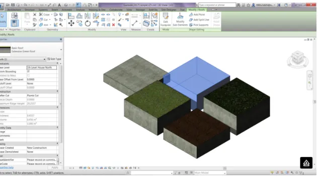
Figure 4-3-6. Four BIM element model types of green roof and concrete roof ... 50
Figure 4-3-7. The BIM element models containing the green roof and the water tank . 51 Figure 4-4-2-1. Roof profile and the thermal model ... 57
Figure 4-4-2-2. Developing and validation process ... 62
Figure 4-4-3-1. System architecture of BIM-enabled Blue-Green design tool ... 66
Figure 4-4-3-2. Dynamo script layout of BIM-enabled Blue-Green design tool ... 67
Figure 5-1-1. Case study - Civil Engineering Research Building and its BIM model. .. 68
Figure 5-1-2. The building mass model of CERB and the BIM element models. ... 69
Figure 5-1-3. The input interface of the Blue-Green design tool. ... 70
Figure 5-1-4. The windows form of LID analysis results. ... 71
Figure 5-1-5. The windows form of thermal analysis results ... 73
Figure 5-1-6. The BIM project model contained the Blue-Green design ... 73
Table 2-1-1. Lessons learned from case studies [15] ... 7
Table 2-1-2. Development stages of the BG Design Brief [19] ... 7
Table 2-2-1. The definition of BIM (Modified from [38] ) ... 10
Table 2-2-2. BIM Uses Purposes and Objectives [41] ... 11
Table 3-3-1. The primary components of IDM [68] ... 24
Table 3-4-1. The object specifications of BOMs [11] ... 25
Table 3-4-2. Level of development and model element content requirements [75] ... 26
Table 3-5-1. The strengths and the weaknesses of both Dynamo and Revit Macro (modified from [85]) ... 33
Table 4-3-1. Three Types of Revit family [95] ... 40
Table 4-3-2. Level of Development of BIM element model with the Blue-Green design [78] ... 41
Table 4-3-3. Level of Definition of extensive green roof system [96] ... 42
Table 4-4-1-1. Input variables of the LID analysis method ... 53
Table 4-4-1-2. Output variables of the LID analysis method ... 54
Table 4-4-1-3. The required water retention depth of the project site with LID ... 55
Table 4-4-2-1. Input variables of the thermal model ... 59
Table 4-4-2-2. Output variables of the thermal model ... 61
Table 4-4-3-1. The variables of the user input of the design tool ... 64
Table 8-1-1. Thermal data of green roof case one ... 91
Table 8-1-2. Thermal data of green roof case two ... 92
Table 8-1-3. Thermal data of green roof case three ... 92
Table 8-1-4. Thermal data of green roof case four ... 93
doi:10.6342/NTU201803891
1
1. Introduction
1.1 Research Background and Research Problem
Over the past decades, the pace of urbanization is fast and the impact of urbanization is huge around the world. According to United Nation’s report [1], the growth of urban population is massive. Urban population comprises more and more percentage of total population since 1950. There is a continuous trend shown not only in developing countries but also in developed countries. Furthermore, there is evidence showing that urbanization results in negative environmental impact [2-6]. Concerning that more and more people live in the urban area, the living quality of the urban and the surrounding environment will become worse and worse.
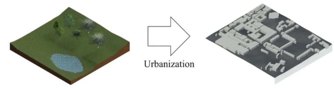
In the process of urbanization (see Figure 1-1), land surface is changed and ecological resilience is destroyed. Greenery plants are replaced by grey buildings, and ground is covered by asphalt and concrete. Open watercourses are covered as sewers or even removed.
Figure 1-1. From rural to urban environment
The changes of the land surface will result in a series of problems. First, the energy and water demand of the land are increased because of high population density with corresponding human activities. Second, the risk of urban flooding is increased due to
impervious surfaces. The original land surface is replaced by man-made infrastructure with low infiltration capability. Once the precipitation in the urban area increases, the runoff will increase to result in flooding. The potential impact of flooding disaster is huge associated with the development of urbanization. Third, the change of the local climate influences complex hazard. For the surface of high-rise building affects the effect of turbulent flow and heat storage, the phenomenon of Urban Heat Island (UHI) is generated according to these associated effects. The UHI includes a series of related effects such as urban breezes, intensive air pollution, highly probability of intense thunderstorms, discomfort in living area, disruption of human activities due to elevated temperatures, health issues, and higher energy consumption in air conditioning [2][3]
[6-9]. These effects may also contributed by climate change.
For mitigating these effects, the urban area is required to be planned and developed in more sustainable and resilient way. In recent years, Blue-Green design approach [3]
is proposed to reduce the negative impact of climate change in urban area. The blue (water) measures contains water supply, waste water, and rain water drainage systems.
The green (vegetation) measures contains green roof, green wall and greenery space.
The Blue-Green design integrated blue and green measures together to provide sustainable design with environmental resilient capacity and social benefits.
Although the concept of the Blue-Green design is straight forward, it is hard to be conducted for the complexity of multidiscipline collaboration [10] (See Figure 1-2). The Blue experts are responsible for the design of water system, and the Green experts are responsible for the design of greenery system. In conducting the Blue-Green design, it is needed to consider design interaction between Blue and Green systems for evaluating integrated performance. Therefore, the experts require multidiscipline knowledge for the design interaction. The threshold of multidiscipline knowledge is high. Following
doi:10.6342/NTU201803891
3
the mindset of work specialization, it is more applicable to establish collaboration environment for Blue and Green experts to create the project design reflecting the employer‘s requirements, analyze Blue-Green system with agreed approaches and review the performance of the overall Blue-Green design in consequential procedures.
Concerning that traditional 2D CAD platform supports limited capability in managing the design parameters of Blue-Green system, an integrated design platform is required for the collaboration environment. Nowadays, Building Information Modeling (BIM) [11] is the promising technology used to enhance the quality of design and managing the information flow of project. With the purpose of implementing the Blue-Green design in design process, this research proposes using BIM technology creating collaboration environment to support Blue and Green experts exploring design options.
Figure 1-2. Interface between blue and green experts [10]
The challenge to couple BIM and the Blue-Green design is wrapping the content of the Blue-Green design into the design and analysis process supported by BIM [12][13].
Even the emerging BIM technology provides integration design platform, there are still lack of BIM element models represented the system of the Blue-Green design and customized design tools to evaluate the performance of the Blue-Green design to be made. The BIM element models are containers carrying product information, but seldom BIM element models are designed according to the principle of integration water and greenery system. Furthermore, Blue and Green experts should evaluate the
performance of BIM project model with agreed analysis approaches. The analysis approaches could be formulated as customized design tool in BIM platform. Once BIM project model is analyzed and the BIM element models of the Blue-Green design are created or modified according to the analysis results, the design content of the Blue- Green design can be properly conveyed to the following designer and contractor. With the BIM element models and customized design tool prepared, Blue and Green experts can conduct design process with expected design information flow. Therefore, the collaboration interface between experts with different disciplinary expertise can be clarified, and the design content can be coordinated to maintain the design quality.
1.2 Research Objective
For the design interaction between Blue system and Green system is multidisciplinary design issue which is difficult to be evaluated, it requires holistic methodology creating collaboration environment for design teams to initiate and analyze the content of the Blue-Green design in the design process. Once the collaboration interface in collaboration environment is clarified, the integrated design outcomes of the Blue-Green design can be assessed and the overall performance of the building design can be optimized by experts with multi-disciplinary knowledge.
The major objective is to develop a BIM-enabled design framework for design team preparing collaboration environment to create the Blue-Green design solution. The framework supports design teams to analyze and form the building design in early design stage. Design teams can continuously collaborate and develop BIM project model with BIM element models of the Blue-Green design in the following design stages.
doi:10.6342/NTU201803891
5
1.3 Thesis Organization
There are six chapters with reference and appendix in this thesis. In the chapter 2, there are literature reviews on the Blue-Green design, BIM with sustainable design and current limitation. In the chapter 3, it is the methodology of this research and the structure of a BIM-enabled Blue-Green design framework is shown. In the chapter 4, it uses water tank and green roof as case study to implement the solution of design framework. In the chapter 5, it shows the scenario studies and discusses the feedback from expert interview. The conclusion of the research is stated in the chapter 6.
2. Sustainable Building with Blue-Green Design and BIM
2.1 Sustainable Building Design and Blue-Green Design
The original idea of the Blue-Green design is combining the Blue measures and Green measures to provide disaster resilience of urban infrastructure to against climate change. There are several projects related to the Blue-Green design research. A research project named Green and Blue Space Adaptation for Urban Areas and Eco Towns (GRaBS) [14] is conducted to raise awareness about green and blue infrastructure. In GRaBS project, Kazmierczak and Carter [15] collected practical cases using green and blue infrastructure and listed valuable suggestion in Table 2-1-1. It is obvious that effective communication and collaboration between stakeholders are the key of success.
After GRaBS project, there is a Blue-Green Cities [16] project focusing on similar topic.
The Blue-Green Cities project intends to combine water management and green infrastructure to recreate water cycle. Followed by the concept of Blue-Green Cities, Hoang and Fenner [17] proposed using sustainable urban drainage systems and green infrastructure for storm water management. Almost the same time, an EU funded project called Blue-Green Dream [18] synergizes urban blue and green systems as Blue- Green solution to enhance urban environment with multiple benefits. The benefits could be air pollution reduction, biodiversity improvement, energy saving, food supply noise reduction and surface runoff delay…etc. Božović et al. [19] propose a BG systems planning methodology listed in Table 2-1-2. The scenario of the methodology is urban planning stage. In the beginning, project requirements should are defined. Then, the analysis and optimization process is the conducted with project requirements and project data. The BG Design Brief is the output of the whole process. The stakeholders include project developers, planning team, BG team, approval bodies and public.
doi:10.6342/NTU201803891
7
Table 2-1-1. Lessons learned from case studies [15]
Suggestions
1. Triggers for action, or the reasons why an action is considered by the organization
2. Continuing leadership and championship
3. Raising awareness within the organization, amongst stakeholders and with the wider public
4. Collaborative working; how internal and external collaboration, and in particular cooperation with research institutes, has facilitated a stronger adaptation response
5. Learning from others, in terms of adaptation processes and/or adaptation actions 6. Developing a sound evidence base, either using in-house expertise or by
outsourcing experts
7. Public engagement on adaptation issues
8. Embedding adaptation in decision making through policies, plans, regulations or incentives, and via close collaboration with developers
9. Funding for adaptation responses
10. Monitoring and evaluation of adaptation responses
Table 2-1-2. Development stages of the BG Design Brief [19]
Stages Actions Stage 1 -
Project requirements and data collection
Definition of project goals, performance targets and indicators.
Gathering and mapping of project requirements and design data (e.g. potential Nature Based Solutions, problems, planning opportunities, local climatic conditions and available water resources).
Stage 2 - Analysis and optimization
Analysis and optimization.
Development of metrics for target indicators.
Analysis of potential synergy benefits between urban components.
Design of candidate solutions.
Detailed comparative analysis to develop optimized integrated solutions.
Stage 3 - Design Brief production
BG Design Brief production.
Completion of detailed BG Design Brief, containing project requirements (based on all stakeholders’ input) and agreed optimized concepts and solutions.
In recently years, more and more studies have contributed on sustainable building [20]. In general, sustainable building is also known as green building. The concept of sustainable building is to improve efficiency in resource consumption and reduce impact on human health and environment [21]. For example, it involves issues such as energy efficiency strategy, water recycling system and renewable energy design [22].
According to an energy modeling guide [23] published by the American Institute of Architects, it suggested that architect can use energy modeling in design stage to improve the energy performance for reducing building energy usage. Another report [24]
published by Royal Institute of British Architects provide guidance for architect to conduct sustainable building design along with design stage.
As mentioned above, the original idea of the Blue-Green design focuses on urban scale and the idea of sustainable building design focuses on building scale. For the common feature of these two concepts is to reduce the environmental impact, the intersection of the concepts could be made. According to the BG systems planning methodology, the BG Design Brief with urban planning requirements is formulated as output. And so forth, the building design requirement of the BG systems can be a subset of the BG Design Brief. It is assumed that buildings with the Blue-Green design can become parts of urban Blue-Green infrastructure. In this research, we emphasize on building scale to develop the Blue-Green design.
doi:10.6342/NTU201803891
9
2.2 Building Information Modeling
In construction industry, BIM is the most popular technology in recent decade.
There are more and more countries applied BIM in public construction projects [25][26].
This trend is across North America [27], European area [28], and even Asia continent [29][30]. The concept of BIM can be traced back to the 1970s when Eastman et al.
introduced the idea of “Building Description System” [31]. In 1989, the term of
“Building Model” is described by Simon Ruffle [32]. Until 1992, “Building Information Model” is first time to be used in a journal paper published by G.A. van Nederveen and F. P. Tolman [33]. In 1999, Eastman published the term of “Building Product Models”[34]. After 2002, the term of “Building Information Model” and “Building Information Modeling” are widely introduced by Autodesk [35]. Compared to the terminology proposed by Autodesk, the corresponding term of Graphisoft and Bentley Systems are “Virtual Building” and “Integrated Project Models” [36][37].
Along with the development of terminology, it is shown that BIM involves the methodology for shaping and describing the information of building in the virtual world.
In defining the meaning of BIM, the interpretation could be the data model contained building information or the process to create the data model. The definitions of BIM are listed Table 2-2-1 [38]. Besides the definition above, BIM could also described as
“Building Information Management” which manages the process to create and share the building information across the building lifecycle [39].
According to the Macleamy curve [40], the cost of design change could be lower down when design team arrange time and effort to integrate design in the early stage of building lifecycle. Therefore, BIM is the entry point to help design team in creating and sharing design content in efficient and consistent way to avoid mistakes. The purposes of BIM use can be categorized as five types in Table 2-2-2 [41].
Table 2-2-1. The definition of BIM (Modified from [38] )
Definition Source
Define BIM as model
A BIM is a digital representation of physical and
functional characteristics of a facility. As such it serves as a shared knowledge resource for information about a facility forming a reliable basis for decisions during its lifecycle from inception onward.
National Institute of Building Science (NIBS) [39]
Discrete set of electronic object-oriented information used for design, construction and operation of a built asset.
PAS 1192- 5:2015 [42]
Digital representation of the physical and functional characteristics of a building over its life cycle.
BS 8536:2010 [43]
A rich information model, consisting of potentially multiple data sources, elements of which can be shared across all stakeholders and be maintained across the life of a building from inception to recycling.
National Building Specification (NBS) [44]
Shared digital representation of physical and functional characteristics of any built object (including buildings, bridges, roads, etc.) which forms a reliable basis for decisions.
BS ISO 29481- 1 2010 [45]
Define BIM as process
Is a BUSINESS PROCESS for generating and leveraging building data to design, construct and operate the building during its lifecycle. BIM allows all stakeholders to have access to the same information at the same time through interoperability between technology platforms.
NIBS [39]
Building Information Modelling is digital representation of physical and functional characteristics of a facility creating a shared knowledge resource for information about it forming a reliable basis for decisions during its life cycle, from earliest conception to demolition.
NIBS [46], Royal Institute of British Architects (RIBA) [47]
The development and use of a multi-faceted computer software data model to not only document a building design, but to simulate the construction and operation of a new capital facility or a recapitalized (modernized) facility.
General Services Administration (GSA) [48]
Construction of a model that contains the information about a building from all phases of the building life cycle.
ISO 16757-1:
2015 [49]
doi:10.6342/NTU201803891
11
Table 2-2-2. BIM Uses Purposes and Objectives [41]
BIM Use Purpose BIM Use Objective Synonyms
Gather
to collect or organize facility information administer, collect, manage, acquireGenerate
to create or author information about thefacility
create, author, model
Analyze
to examine elements of the facility to gain a better understanding of itexamine, evaluate
Communicate
to present information about a facility in a method in which it can be shared or exchangedexchange
Realize
to make or control a physical element using facility informationimplement, perform, execute,
The five types of BIM use purpose include major activities in building lifecycle.
BIM model could be the data source to organize facility information. In BIM platform, BIM project model could be created and evaluated in parametric software environment.
With the outcome of the BIM project model, the building information could be shared and even fabricated. According to the BIM Project Execution planning guide [50] and the survey [51] evaluating the frequency and benefit of BIM use, 3D coordination, Design Reviews and Design Authoring are top three BIM uses. The importance of maintaining correct and consistent design information is shown.
2.3 Limitations on Current BIM-based Sustainable Building Design
BIM can be used to create design alternatives. With the use of BIM, sustainable building design concerning rainwater harvesting, solar access, and recycled content can be conducted [52]. For example, Levy [53] proposes a worksheet for designer to size green roof with rainwater harvesting calculation and BIM project model. In this scenario, designer can use existing functions of BIM platform to extract required information. Generally, most building performance analysis can be conducted with the use of Building Energy Modeling (BEM) tool [54]. In the BIM guide for energy performance [55] published by General Service Administrative of United State, it is suggested that energy analysis can be done with the use of BIM project model. Designer can transfer BIM project model into green building format as input of energy analysis software. However, there are some limitations on current approaches of BIM-based sustainable building design.
(1) User defined manual operation for sustainable building design
For there are some calculation principles of sustainable building design not included in BIM platforms or BEM tools, designer is required to define a series of operations of different software to conduct the calculation. The operations could be collecting information from web database, extracting information from BIM platform, setting calculation rules and conduct calculation in spreadsheet software. During the process of sustainable building design, it is needed to check information consistency of each manual operations. After the calculation is done, designer references the calculation results to optimize the building design in BIM platform. The feature of this approach is flexible in switching calculation principles but lack of effective mechanism in managing design information among the software. The configurations of the operations are hard to be reused.
doi:10.6342/NTU201803891
13
(2) Combined operation of BIM platform and BEM tool for sustainable building design For there are related analysis functions of sustainable building design contained in BEM tools, designer can use BIM project model as information source to export building information to BEM tool conducting analysis. In this approach, designer creates BIM project model in BIM platform, exports BIM project model from BIM platform to BEM tool, and checks the completeness of building information in BEM tool. It exists interoperability issues in exchanging information between BIM platform and BEM tool [54]. Designer is required to remodel the building geometry and reassign material properties in BEM tool. After the analysis results are obtained, designer references the analysis results shown in BEM tool and modify the BIM project model in BIM platform to process the next design iteration. Obviously, the cost of maintaining design information between BIM platform and BEM tool is high.
In designing building with the Blue-Green design, it requires a series of design activities supported by BIM to deal with multidisciplinary design requirements. For instance, the BIM element models should be created as the physical representation of the Blue measures and the Green measures. The BIM-enabled customized design tool with Blue-Green performance analysis function is also critical for handling design interaction between systems to evaluate potential benefits. Furthermore, the processes to identify the design requirements of the Blue-Green design and develop BIM project model in collaborated way play important roles in the design stage. With the above limitations and concerns, the proposed collaboration environment should support new approaches of BIM-based sustainable building design conducting the Blue-Green design.
3. Development of BIM-enabled Blue-Green Design Framework
3.1 Design of BIM-enabled Blue-Green Design Framework
The feature of the Blue-Green design is to combine greenery system and water system as an integrated system. In order to design the size and the capacity of the integrated system, it is required to consider the design requirements of each sub-system and the interaction between design parameters. For the design requirements are too complex to manage design parameters, BIM software with parametric design capability is selected to support the Blue-Green design. Although BIM software can be used as an integrated design platform in designing building parametrically, a series of configuration is needed to create corresponding BIM element models of each sub- system with required design parameters. Even the BIM element models are prepared; it is still lack of analysis and design functions of the integrated system.
According to the document [41] published by Pennsylvania State University, the BIM uses purposes can be defined into five types with each BIM use characteristics.
However, the design process consists of several design activities involving different BIM uses. In implementing the Blue-Green design, it shall require almost all the BIM uses listed in Tables 2-2-2. With reference to the document [41], this research proposes a BIM-enabled Blue-Green design framework for helping design teams preparing collaboration environment to analyze and design building with the Blue-Green design in the early design stage. The collaboration environment provides clear collaboration interface and process along with appropriate design solutions for design teams to conduct design.
The aim of this framework is supporting Blue and Green design teams to clarify collaboration interface and process with procedures of creating the design toolkits for
doi:10.6342/NTU201803891
15
Blue-Green design. The framework considers integration and parametric design of the Blue and Green components of a building system with customized analysis functions in BIM platform.
The prerequisite of the framework is that design teams have BIM ability to collaborate building design using BIM model during design stage. The BIM ability contains the knowledge to create BIM-based customized design tool using visual programming language. The assumed research scenario is that the Blue-Green design is one of the major methodologies to be applied to fulfil the project requirements.
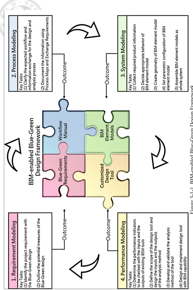
In selecting the BIM uses [41], the first step is to identify objectives and the second step is to determine the BIM use characteristics such as facility element, facility phase, discipline and level of development. For the BIM-enabled Blue-Green design framework, the above two steps are concerned. Furthermore, the steps to create a customized design tool and a workflow manual are defined in the framework to support the Blue-Green design. There are four modeling approaches in the BIM-enabled Blue- Green design framework shown in Figure 3-1-1. The term of “modeling” in this framework is an activity for design teams to define and describe things such as the statement of the project requirements, the representation of physical objects, the performance indicator, or the design process.
Concerning that the employer’s requirement is the objective of the project, the first modeling approach of the BIM-enabled Blue-Green design framework is the requirement modeling. After the project requirements related to the Blue-Green design are defined, the candidate measures of the Blue-Green design can be chosen by design teams to fulfil the requirement. The outcome of the requirement modeling is called Blue-Green requirements. The second modeling approach is the process modeling with a workflow manual as output. The Blue-Green requirements and the potential follow-up
actions such as creating BIM element models and customized design tool should be considered in the workflow manual. With the Blue-Green requirements and the workflow manual prepared, the measures of the Blue-Green design is modeled as BIM element models containing product information in the system modeling. After the BIM element models are implemented, design teams can create a BIM project model that represents the overall building design and load the BIM element models as part of the BIM project model. In order to satisfy the threshold of the Blue-Green requirements and optimize the capability of the measures, it is required to quantify the performance of the Blue-Green design. The purpose of the performance modeling is to develop a customized design tool with analysis function to model the performance of the Blue- Green design for optimization. In the performance modeling, the key tasks to create customized design tool for the Blue-Green design are introduced. With the above modeling outcomes prepared as design toolkit, design teams could use the design toolkit conducting the Blue-Green design under clear collaboration interface and process.
The framework can be used in conducting analysis and design process in the early design stage. The four modeling approaches are interrelated with each other. The user of the framework are design teams including architects, BIM consultants or sustainability consultants representing Blue Green experts. The exact role of Blue expert or Green expert differs from project to project. Each design team may consider the Blue-Green design together in different aspects. The detailed classification of Blue expert or Green expert is not considered in this research. For the design process, it is suggested that lead designer such as architect is responsible for the requirement modeling and the process modeling. The system modeling and the performance modeling could be conducted collaboratively among design teams such as BIM consultants or sustainability consultants.
doi:10.6342/NTU201803891
17
Figure 3-1-1. BIM-enabled Blue-Green Design Fram ework
3.2 Key Tasks of Requirement Modeling
In this research, the workflow of the design process is referenced to the PAS 1192-2 document [56], which is the source of the incoming ISO 19650-1 standard [57][58].
In the beginning of a construction project which is the Strategy stage in the information delivery cycle [56] , the employer will formulate the project requirements into a Strategic Brief and an Employer Information Requirement (EIR) [42][56]. The Strategic Brief is a document written by employer to provide sufficient project information for consultant to study the feasibility of the project [59][60]. The EIR is a pre-tender document containing the information requirement towards the expected built assets of the construction project [56]. The suppliers will prepare a pre-contract Building Information Modeling Execution Plan (BEP) to demonstrate the proposed approach and the corresponding capability to fulfil the EIR [56]. After the suppliers reward the contract, they will prepare a post-contract BEP with a Master Information Delivery Plan (MIDP) to detailed defining how the suppliers and the supply chains deliver the project information [56]. In the Brief stage of the information delivery cycle, an initial Project Brief based on the Strategic Brief is coordinated by lead consultant or lead designer [61]. The Project Brief is the key document containing employer’s requirement about the nature of the expected built asset [61][62]. In the Concept stage of the information delivery cycle, architect as lead designer will prepare a BIM project model, which is named Project Information Model in in the information delivery cycle [56] as an initial design response to the Project Brief [63]. The finalized Project Brief is formulated in the end of the Concept stage [61], and the BIM project model will be developed according to the Project Brief in the following stages.
doi:10.6342/NTU201803891
19
In the requirement modeling, it focuses on the Concept stage in the information delivery cycle [56]. There are two modeling key tasks listed below:
(1) Identify the project requirements with the Blue-Green design
In preparing design response to the Project Brief, the sustainability targets of the project will be formulated. Design teams will review relevant international, national, and local sustainability policies to explore potential design options. The sustainability assessments such as LEED, BREEAM and Passivhaus can also be considered according to the Project Brief. With the above consideration and employer’s business case, the project requirements related to the sustainability targets, which are related to the greenery or water system design, can be identified.
Besides, once there exists the previous design toolkits for similar Blue Green design project, the Blue-Green requirements can be formulated with these resources.
(2) Outline the potential measures of the Blue-Green design
For providing potential environmental services, there are potential services provided by the Blue measures or the Green measures [64]. The Blue measures could be water square, permeable pavement and rainwater tank. The Green measures could be green roofs, green shores and park. Each measure has advantage and disadvantage in different environmental aspect. In order to optimize the benefit of the design measures, the Blue-Green design concept is integrating the Blue measures and the Green measures in complementary way.
The scope of this framework is focusing on the design measures of building design. The Blue measures of building design could be water roof or rainwater tank.
The Green measures of building design could be green roof or green wall. With the project requirements related to the Blue-Green design prepared, design teams can outline the combination of the Blue measures and the Green measures to evaluate design alternatives to fulfil the project requirements. The output of the requirement modeling are the Blue-Green requirements including the project requirements related to the Blue-Green design, the outlined Blue measures, and the outlined Green measures.
doi:10.6342/NTU201803891
21
3.3 Key Tasks of Process Modeling
With the Blue-Green requirements prepared, a workflow manual is needed to describe the collaboration interface and process. This research uses two concepts describing below to support the workflow manual.
In the building design process proposed in the Figure 3-2-2, it requires Common Data Environment (CDE) as a working environment to support design collaboration.
There are four phases of CDE [65]. In the CDE, a lead designer of the project will coordinate the collaboration process [66]. The first task team is usually architect team.
The architect team will form an initial BIM project model in the “Work in progress”
folder. After the initial BIM project model is checked by the lead designer, it can be uploaded to “Shared” folder to be shared among the project teams. The rest task teams such as landscape architect team, structural engineer team, mechanical engineer team, electrical engineer team, and plumbing engineer team can reference the initial BIM project model as a foundation to develop the content of the model. The lead designer will also check, review and approve the coordinated models before it is uploaded to
“Shared” folder. When it comes to the end of design stage or the project milestone, employer will authorize the BIM project model and the corresponding design documents to be published in “Published documentation” folder. Besides, the “Archive”
folder is used to record the history data of the project information at each project milestone. The CDE is an iterative process repeating above steps.
For supporting the business requirement, there is an open data format of BIM model called Industry Foundation Class (IFC) [67] designed to support all the business requirement for all project stages. In general, it is feasible to exchange information under particular business requirement during design stage [68].
Therefore, Information Delivery Manual (IDM) is a document to support the BIM
use, and the project stakeholders can use to clarify the collaboration interface and process [69]. There are international standards [70][71] to define the methodology in formulating an IDM, and there are four components of IDM listed in Table 3-3-1. For the use of IDM is not only for supporting the business requirement but also developing the software solution, there exists barriers in mapping the relationship between Process Maps, Exchange Requirements, Functional Parts and Model View Definition (MVD) which is a is a subset of IFC for particular BIM use [72][73].
In order to apply the concept of CDE and IDM to formulate a workflow manual for the Blue-Green design, there are two modeling key tasks shown below.
(1) Clarify the expected workflow and information exchange for the design and analysis process
In modeling the design process, it requires experienced consultants or designers to outline the work items for the specific design stage. The requirement identification of the Blue-Green design, the use of the BIM element models of the Blue-Green design and the customized design tool should be considered as the work items. The corresponding workflow is composed by arranging the work items and relationship between each character in the project. The structure of the workflow is developed under CDE collaboration concept. Therefore, the information exchange is clarified according to the work items in the workflow.
doi:10.6342/NTU201803891
23
(2) Document the information using Process Maps and Exchange Requirements
For taking the advantage of IDM methodology, Process Maps and Exchange Requirements are used to describe expected workflow and information exchange in formal document. In creating the Process Maps, the expected workflow is illustrated in Business Process Model and Notation (BPMN) [74] format. The Exchange Requirements is formulated according to the Process Maps. It is suggested to reference existing Process Maps and Exchange Requirements in published IDM to shorten this process of documentation. Because the process modeling only focuses on satisfying the business requirement, developing IFC compatible software solution is not considered. The outcome of the workflow manual is composed of Process Maps and Exchange Requirements.
Table 3-3-1. The primary components of IDM [68]
IDM elements Descriptions
Process Maps A process map describes the flow of activities within the boundary of a particular topic.
The purpose of a process map is to gain an understanding of the configuration of activities that make it work, the actors involved, the information required, consumed and produced.
Exchange Requirements
An exchange requirement is a set of information that needs to be exchanged to support a particular business requirement at a particular stage of a project.
Typically, for IDM as presently established, the set of information should be defined within the IFC model. However, the IDM approach will also work with sets of information defined within other industry standard models such as the Geographic Markup Language (GML) as defined by the Open Geospatial Consortium (OGC).
An exchange requirement is intended to provide a description of the information in non-technical terms. The principal audience for an exchange requirement is the user (architect, engineer, constructor etc.). It should however also be used by the solution provider since it provides the key to the technical detail that enables the solution to be provided.
Functional Parts
A functional part is a unit of information, or a single information idea, used by solution providers to support an exchange requirement.
A functional part describes the information in terms of the required capabilities of the industry standard information model upon which it is based. For IDM as presently established, the functional parts are based on versions of the IFC model.
A functional part is fully described as an information model in its own right as well as being a subset of the information model on which it is based.
Concepts A concept is a fragment of information that can be used in a functional part (where it is bound to a release of the IFC model) or to an exchange requirement (where it is expressed in generic terms). It can be used to capture the basic functionalities within a model such as naming, identification etc. A concept does not need to be simply related to a single entity or even to a whole entity. For instance, the concept of a software identifier simply describes how a globally unique identifier attribute is asserted for an entity.
doi:10.6342/NTU201803891
25
3.4 Key Tasks of System Modeling
In the BIM-enabled Blue-Green design framework, the measures of the Blue-Green design are described in the form of BIM Object Models (BOMs) [11]. Eastman defines that BOMs are 2D and 3D geometrics representation of physical products. These products includes doors, windows, equipment, furniture, fixtures, walls, roofs, ceilings, floors and specific products. There are primary information content needs of BOMs listed in Table 3-4-1.
Table 3-4-1. The object specifications of BOMs [11]
Information content
1
2D or 3D geometry (2D for carpeting, and film-like finishes)2
Material representation, with name and model graphical finish (texture map)3
Parametric geometry, if not fixed4
Connection locations and requirements with other systems: electrical, plumbing, telecommunications, structural, airflow5
Performance specifications, operating life, maintenance cycle, lighttransmittance, and other specs used in selection (varies by type of equipment)
6
Luminous Intensity Distribution Curve (for light fixtures)7
Links to product distribution channelsIn creating BOMs, the information content will change depending on design stage.
In G202 document [75] published by the American Institute of Architects (AIA), there is a definition called Level of Development (LOD) describing the specific information content requirement and corresponding authorized uses for each model element. The meaning of “model elements” is similar to “BOMs” in the following content, and the general content requirements are listed in Table 3-4-2.
Table 3-4-2. Level of development and model element content requirements [75]
LOD Model Element Content Requirements
100
The Model Element may be graphically represented in the Model with a symbol or other generic representation, but does not satisfy the requirements for LOD 200. Information related to the Model Element (i.e. cost per square foot, tonnage of HVAC, etc.) can be derived from other Model Elements.200
The Model Element is graphically represented within the Model as a generic system, object, or assembly with approximate quantities, size, shape, location, and orientation. Non-graphic information may also be attached to the Model Element.300
The Model Element is graphically represented within the Model as a specific system, object or assembly in terms of quantity, size, shape, location, and orientation. Non-graphic information may also be attached to the Model Element.350
The Model Element is graphically represented within the Model as a specific system, object, or assembly in terms of quantity, size, shape, location,orientation, and interfaces with other building systems. Non-graphic information may also be attached to the Model Element.
400
The Model Element is graphically represented within the Model as a specific system, object or assembly in terms of size, shape, location, quantity, and orientation with detailing, fabrication, assembly, and installation information.Non-graphic information may also be attached to the Model Element.
500
The Model Element is a field verified representation in terms of size, shape, location, quantity, and orientation. Non-graphic information may also be attached to the Model Elements.doi:10.6342/NTU201803891
27
Aside from the LOD definition from the US, there is a similar model element definition from the UK. The Level of Definition (LOD/LOI) contains Level of Details (LOD) and Level of Information (LOI) [76][77]. The LOD here is used to describe the level of geometric detail including 2D and 3D geometry, and the LOI is used to describe the level of required information according to design stage. The Level of Development (LOD) from the US is generic and flexible, and the Level of Definition (LOD/LOI) from the UK is more feasible in implementation aspect. It is suggested to consider both definition in creating model elements.
In this research, the term of “BIM element models” is used to represent the meaning of “BOMs” or “model elements” for maintaining the naming consistency. In modeling the BIM element models of the Blue-Green design, it is composed of blue (water) measures and green (greenery) measures. There are five modeling key tasks proposed.
(1) Collect required product information
Information modeling is the first step of the system modeling. For the product information is the source for information content of BIM element model such as Table 3-4-1, it is suggested to collect the product information as complete as possible. Once there is lack of information in particular area, the reference information collected from similar product cases can be used to replace the missing information. With reference to the Blue-Green requirements and the workflow manual prepared in previous paragraph, the information needed for the Blue-Green design can be outlined. Also, the LOD specification document [78] and NBS BIM toolkit [79] website are official resources contained BIM element model definitions mentioned above. For these resources provide the descriptions of specific BIM element model toward corresponding authorized uses, it indicates the descriptions of suitable information contained in BIM element model as reference for selecting needed product information. On the basis of above
considerations, the selected product information is prepared for creating the BIM element models of the Blue-Green design to convey design intent.
(2) Decide appropriate behavior of BIM element model
The process to model the behavior of BIM element model is to decide how BIM element model updates itself when its content is changed [11]. In general, BIM platform has built-in behavior defining the relationship that BIM element model adjusts itself with related BIM element models or parameters automatically. In modeling the behavior of BIM element model, it is suggested to consider the potential BIM uses. For example, Kuo [80] presented BIM-based energy analysis for BIPV building. When BIM project model of the BIPV Experiment Demonstration House is transferred to gbXML format [81] which is data schema used for energy analysis software, the BIM element model of BIPV module is not transferred to this format for interoperability issue. As a result, the BIM project model used for energy analysis could be different to the model used for construction coordination even in the same project. For there is no only guidance in creating BIM project model, it depends on the purpose of BIM use to choose suitable approach to model building elements. Designer can either choose BIM element model template of specific built-in type to create BIM element model with existing product, or use generic BIM element model template to create new BIM element model with customized parametric behavior.
(3) Create geometry of BIM element model
In modeling the geometry of the Blue measures and Green measures, the major concern is to make BIM element model in simple shape but maintain the functionality.
Modeling approaches such as Constructive Solid Geometry (CSG) [82] can be used for geometry modeling. The feature of CSG is to enable modeler using Boolean operators to combine simple 3D objects into overall 3D model. It is suggested to maintain the
doi:10.6342/NTU201803891
29
quantity of 3D objects and the polygons as minimum as possible. The graphical loading of computing device could be reduced when BIM element models are loaded into BIM project model.
(4) Set parametric configuration of BIM element model
There are three aspects in parametric modeling. One is to set product information to parameters of BIM element model. The other one is to set constrain parameters to control geometry of BIM element model. The rest one is to set parameters according to the formula combined with information parameters or constrain parameters. The relationship created between parameters and geometry is used to design building model with versatility.
(5) Assemble BIM element models as whole system
In general, the BIM element models of the Blue measures and Green measures are created in different categories. It is required to encapsulate two kind of BIM element models as a whole system package and the parametric relationship between the Blue measures and Green measures is needed to be created. The implementation for above modeling key tasks are varied according to the feature of selected BIM platform.
Therefore, the integrated BIM element models are prepared to represent the solution of the Blue-Green design.
3.5 Key Tasks of Performance Modeling
In modeling the performance of the Blue-Green design, it requires customized design tool with building performance analysis function for architect to evaluate the design alternatives. There are three key tasks proposed here.
(1) Determine the performance indicators to be checked with the inputs and the outputs of existing BEM tools
The first step is to determine the expected performance indicators of the Blue- Green design according to the Blue-Green requirements. The performance indicators and the corresponding analysis methods could be derived from urban planning policy, building regulation or self-developed calculation method.
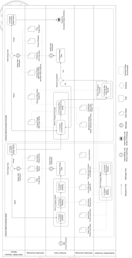
Once the performance indicators are chosen, these indicators can be compared with the inputs and the outputs of existing BEM tools listed in Figure 3-5-1[54].
While the indicators can satisfy part of the Blue-Green requirements but not being listed in the outputs of existing BEM tools, it is recommended to implement the corresponding analysis method. In the other hand, there are circumstances that the indicators listed in the outputs of existing BEM tools worth implementing the analysis methods. Once the outputs of the BEM tools require sophisticated inputs and the indicators can aid in reducing the scope of the design variable, it is also recommended to implement the analysis method with fewer inputs to have perform instant analysis.
doi:10.6342/NTU201803891
31
Building geometry ■ ■ ■ ■ ■ ■ ■ ■ ■ ■ ■ Building orientation ■ ■ ■ ■ ■ ■ ■ ■ ■ ■ ■ ■ Weather file ■ ■ ■ ■ ■ ■ ■ ■ ■ ■ ■ ■ Building envelope constructions ■ ■ ■ ■ ■ ■ ■ ■ ■ ■ ■ ■ HVAC type ■ ■ ■ ■ ■ ■ ■ ■ ■ ■ ■ ■ Building type / function ■ ■ ■ ■ ■ ■ ■ ■ ■ ■
Glazing type ■ ■ ■ ■ ■ ■ ■ ■ ■ ■ ■ Lighting power density ■ ■ ■ ■ ■ ■ ■ ■ ■ ■ Equipment power density ■ ■ ■ ■ ■ ■ ■ ■ ■
Occupancy schedule ■ ■ ■ ■ ■ ■ Lighting schedule ■ ■ ■ ■ ■ ■ Equipment schedule ■ ■ ■ ■ ■ ■
Fuel type ■ ■ ■ ■ ■ ■ ■
Operable windows ■ ■ ■ ■ ■ ■ ■ Operable window schedule ■ ■ ■ ■ ■ ■ System energy efficiency ■ ■ ■ ■ ■ Albedo (roof reflectance) ■ ■ ■ ■ User-defined glazing specifications ■ ■ ■ ■ ■ ■ ■ ■ ■ User-defined envelope construction layers / properties ■ ■ ■ ■ ■ ■ ■ ■ ■
MEP BIM model ■ ■ ■
Water efficient fixtures ■ ■
HVAC component sizings ■ ■ ■ ■ ■
Customizable occupancy schedule ■ ■ ■ ■ ■ Customizable lighting schedule ■ ■ ■ ■ Customizable equipment schedule ■ ■ ■ ■
Plant Data ■ ■ ■ ■ ■ ■
HVAC fan power ■ ■ ■ ■ ■ ■ ■ ■ Required interior design temperatures ■ ■ ■ ■ ■ ■ ■
Energy costs ■ ■ ■ ■ ■ ■ ■ ■
Energy analysis ■ ■ ■ ■ ■ ■ ■ ■ ■ ■ ■ ■ Daylighting analysis ■ ■ ■ ■ ■ ■ ■ ■ ■ ■ ■ Natural ventilation analysis ■ ■ ■ ■ ■ ■ ■ ■ ■ ■ ■ ■ Passive energy potential ■ ■ ■ ■ ■ ■ ■ ■ ■
LEED credit assistance ■ ■ ■ ■ ■ ■
Design alternative ■ ■ ■
Carbon emissions ■ ■ ■ ■ ■ ■ ■ ■ ■ ■ ■
Resource management ■ ■ ■
Thermal analysis ■ ■ ■ ■ ■ ■ ■ ■ ■ ■ ■ Heating / cooling load breakdown ■ ■ ■ ■ ■ ■ ■ ■ ■ ■ ■ ■ Solar analysis ■ ■ ■ ■ ■ ■ ■ ■ Electric lighting design ■ ■ ■ ■
Lifecycle cost analysis ■ ■ ■ ■ ■ ■ ■ ■ ■ ■
Water usage ■ ■ ■ ■ ■
Figure 3-5-1. The inputs and outputs of the BEM tools (extracted from [54])
(2) Define the scope of the design tool and design the inputs and the outputs of the analysis method
The scope of the design tool should be well defined. It is suggested to design the inputs of the analysis method collected from BIM project model as much as possible.
The outputs of the analysis method are the performance indicators in general.
(3) Develop and validate the analysis method of the tool
The analysis method is required to be developed and validated before published as the core of the design tool. In case that analysis method is referenced from existing literature, it is only needed to validate the consistency between analysis method and implementation.
(4) Design and implement design tool with BIM capability
In designing the software architecture of the design tool, the design tool can be formulated in different forms such as plug-in toolkit, standard software or web service depending on different situations. Concerning that the interoperability issue between BIM platform and BEM tools may result in rework, it is better to seek a holistic approach to formulated the design tool. For example, Schlueter and Thesseling [83] create an energy analysis tool using Revit Application Programming Interface (API) to directly extract design data from BIM project model. In the other way, Negendahl [84] reviews about building performance simulation in the early design stage. The review paper suggests using visual programming language as middleware to exchange and maintain consistent design data between design tool and building performance simulation environment. Based on this suggestion, it is applicable to take a step forward to use visual programming language in creating the design tool with building performance analysis.
In order to determine the pros and cons between programming using BIM
![Figure 3-5-1. The inputs and outputs of the BEM tools (extracted from [54])](https://thumb-ap.123doks.com/thumbv2/9libinfo/9608437.634002/45.892.134.780.108.1093/figure-inputs-outputs-bem-tools-extracted.webp)
![Table 3-5-1. The strengths and the weaknesses of both Dynamo and Revit Macro (modified from [85])](https://thumb-ap.123doks.com/thumbv2/9libinfo/9608437.634002/47.892.128.766.914.1134/table-strengths-weaknesses-dynamo-revit-macro-modified.webp)
![Figure 4-3-1. The global trend of BIM software [91]](https://thumb-ap.123doks.com/thumbv2/9libinfo/9608437.634002/53.892.129.763.599.914/figure-global-trend-bim-software.webp)
![Table 4-3-2. Level of Development of BIM element model with the Blue-Green design [78] ElementsLOD 100 LOD 200 Roofing Solid mass model representing overall building volume; or, schematic wall elements that are not distinguishable by type or material](https://thumb-ap.123doks.com/thumbv2/9libinfo/9608437.634002/55.892.125.741.140.1144/development-elementslod-roofing-representing-building-schematic-elements-distinguishable.webp)

![Table 4-3-4. Green roof modeling approach comparison [99] Modeling approach Loadable Family System Family Free form modeling It can be used as tiles to cover the expected green roof area](https://thumb-ap.123doks.com/thumbv2/9libinfo/9608437.634002/63.892.150.763.120.1189/modeling-approach-comparison-modeling-approach-loadable-modeling-expected.webp)