failure. From this a 'required crossconnections' matrix, P,,,,, was formed for each node to represent the involvement of each of the y span pairings at a node in the specific pathset for restoration of each of the S single-span failures that are possible.
(ii) The co-ordinate-constrained gradient search was applied at each node, iteratively inspecting P,7,, to determine aC,/aX,,,,,' in eqn. 5 and to implement the summations in eqn. 4.
(iii) Using the optimised preconnection vectors, Xv,k,". a = 1, ..., N , that resulted from (ii), the readiness bound N J N , was evalu- ated for each network, again using P,7,,, this time to obtain N,. The results are summarised in Table 1.
2
Discussion: Results show that, with the above procedure to pre- configure spare links, an average of 79% of the span-to-span pair- ings required for restoration in the IO test networks could be preconnected in advance of failure. This implies that we could rea- sonably expect to have a useful fraction of the end-to-end paths required for restoration also available instantaneously, without any crossconnect deployment delays. However, to maximise the latter potential we must further devise a means of co-ordinating the total quantities of span-to-span preconnection in the vec- tors a t all nodes so that individual link crossconnections are most coherently related to those at other nodes, thereby forming the maximum number of fully preconnected end-to-end paths for the average restoration case. This is a topic of ongoing work. These first results, however, give significant early motivation, and indi- cate considerable practical benefit from, the overall strategy of preconnection in mesh-restorable networks. Similar results may be obtained with the procedure given for other distributed restoration
protocols and networks
0 IEE 1994
Electronics Letters Online NCI: 19940131
W. D. Grover and M. H. MacGregor (TRLubs & University of Alberta, Edmonton, T6G 2 E l . Canadu)
22 November 1993
Ref er en c es
GROVER. w D.. VENABLES. B.D., MACGREGOR, M.H , and SANDHAM, J H.: 'Development and performance verification of a
distributed asynchronous protocol for real-time network restoration', IEEE J. Se/. Areus Commun., 1991, SAC-9, (l), pp. 112- 125
SAKAUCHI. H , NISHIMURA. Y., and HASEGAWA, s.: 'A self-healing
network with economical spare-channel assignment'. IEEE Globecom '91, pp. 438443
YANG, c.H., and HASEGAWA. s.: 'FITNESS: A failure immunization
technology for network service survivability'. IEEE Globecorn '88, pp. 1549-1554
SR-NWT-002514: 'Digital cross-connect systems in transport network survivability', Bellcore, 1, January 1993
wu. 'r -H., and KOBRINSKI. H . : 'A service time restoration study for distributed control SONET digital cross-connect system self- healing networks'. IEEE ICC '93, pp. 893-899
GROVER, W.D , BILODEAU. TU., and VENABLES. B.D : 'Near-optimal spare capacity planning in a mesh restorable network'. IEEE Globecom '91, pp. 2007-2012
Power control algorithm for cellular radio
systems
J.-C. Lin,
T.-H.
Lee and Y . - T . Su
Inde.rine terms: Cellular radio, Alrorirhms
In a recent paper, Zander presented an optimum transmitter power control scheme to minimise the outage probability for cellular systems and proposed the stepwise removal algorithm (SRA) for use in practical implementations. In the Letter, the authors present a new power control algorithm which considers the transmitter power together with link gains. The algorithm provides better outage probability with only a negligible increase in computational complexity.
Introduction: Frequency reuse is the core concept in cellular mobile systems. The interference due to common use of the same channel limits the system capacity. Transmitter power control is a technique which can be used to reduce cochannel interference and allow as many receivers as possible to obtain a satisfactory recep- tion.
Aein [I] proposed controlling the transmitter power to achieve a balanced carrier-to-interference ratio (CIR). Under the balancing scheme, all receivers experience the same CIR. Unfortunately, it is possible that for a balanced CIR the reception may be unsatisfac- tory for all receivers. To achieve satisfactory reception, some transmitters may need to be prohibited from transmitting. Zander
[2] studied this problem and derived an optimum power control
scheme which minimises the outage probability. However, the computational complexity makes the optimum power control scheme impractical. For this reason, Zander proposed a simple procedure, called the stepwise removal algorithm (SRA), for prac-
tical implementations.
In this Letter, we propose a new power control scheme that takes into account both the transmitter power and the link gains. Numerical results show that, compared with the SRA algorithm, our scheme achieves a smaller outage probability with only a neg- ligible increase in computational complexity.
System model; The cellular system investigated in this Letter con- sists of a finite number of cells. Cells using the same channel are placed symmetrically in a hexagonal grid. Base stations use omni- directional antennas and are located at the centre of the cells. The mobiles are assumed to be uniformly distributed over the cell area. The set of cells using a certain channel at some given instant is called the cochannel set and the size of the cochannel set is denoted by N . All cochannels are assumed to be in use. The total
interference power is modelled as the sum of the powers of all active interferers and the transmission quality is assumed to depend only on CIR. Under these assumptions, the CIR at mobile i is given by
R,
R,
-R,
C I R , =-
T A
- T,LtJ - T I L ,-
T , -Efl
T 3 Z z ) -Tz
where R, is the power received from the j t h transmitter,
T,
is thetransmitter power used by the base station in cell j , L, is the gain on the link between the mobile in cell i and the base station in cell j at some given moment, and Z , = LJL,, is the normalised link gain. The link gain L,, is modelled as L , = A,/d,' where A , is the attenuation factor, d , is the distance between the mobile in cell i
and the base station in cell j , and Y is a constant that models the large scale propagation loss. The attenuation factor models the power variation due to shadowing. We assume that A,, 1 L i , j s N . are independently lognormally distributed random variables with OdB expectation and o d B log variance.
A CIR is defined to be achievable in the cochannel set if there exists a power vector T = [ T , , T,, ..., 7 J r such that CIR, 5 CIR
for all i, 1 s- i L N . Let CIR, be the system protection ratio or the
minimum CIR required for a satisfactory reception. It was shown
[2] that the largest achievable CIR, denoted by
CIR*,
is given byCIR* = l/(L*-l), where h* is the largest real eigenvalue of the positive link gain matrix 2 = [ Z J . Moreover, the optimum power vector T* is the eigenvector of Z corresponding to the eigenvalue
A*.
All mobiles experience the same CIR* when T* is used.Power control algorithms: An optimum power control algorithm (PCA) will, by removing as few cells as possible, find the largest submatrix of Z for which CIR,, is achievable. The following brute force algorithm is ah optimum PCA.
( a ) Algorithm I : Brute force algorithm (BFA)
[A:
(i) Step I : Determine CIR* corresponding to 2. If CIR* 2 CIR,,, then use the eigenvector
T*
and stop, else perform step 2. (ii) Step 2 Remove all combinations of at mostN
- 2 cells and compute the eigenvalues of each reduced system. If for some i, 1 s i 5 N - 2, CIR* 2 CIR,,, then use the corresponding eigenvector and stop, else removeN
- 1 cells and stop.When using the BFA algorithm to remove any combination of n cells (1 a n s
N
- 2), weneed
to determine the eigenvalue and eigenvector pairN !
(3
=z@-zy
times. Therefore, in the worst case, we have to determine the eigenvalue and eigenvector pair
)I
-
.--
'E 0.2 nP
a-8
50.1 m 0(7)
+
(Y)
+...+
&N2)
= 2 N - N - 2-
-times to remove
N
- 1 cells to achieve CIR,,.( b ) Algorithm 2: Stepwise removal algorithm (SRA) [Z]:
(i) Step I: Determine CIR* corresponding to Z. If CIR* 2 CIR,,,
then use the eigenvector Ti and stop; else set N' =
N
and perform step 2.(ii)
Step 2 Remove cell k for which the maximum of the row and column sums,R,
= oF," Z , and RkT =ZF,"'Zk,,
is maximised and form the (W - 1)*
(N' - 1) matrix Z . Determine CIR* corre- sponding to Z'. If CIR* r CIR,,, then use the corresponding eigen- vector and stop; else set N' = N' - 1 and repeat step 2.For the SRA algorithm, to remove one cell, we need to f i d the eigenvalue and eigenvector pair once. So, in the worst case, we need to solve the eigen system
N
- 2 times which is far less than the 2" -N
- 2 times required for the BFA algorithm. However, theS R A
algorithm is not an optimum PCA. To improve the per- formance of the SRA algorithm, we propose algorithm 3. (e) Algorithm 3; Stepwise maximum-interference removal algorithm(SMIRA):
The SMIRA algorithm considers transmitter power to be an important factor for the criterion of removing cells. The idea is
that the larger the transmitter power, the greater the interference it
causes in mobiles in the other cells. Therefore, if a cell which uses a high transmitting power is removed, it is likely that the remain- ing cells can achieve CIR,,. Defme
N' N'
RI = T,
*
21, RT =Z
*
Z,,,=1,3#1 3=1,3#1
and f L a z , I = m u ( & , RT)
The SMIRA algorithm is the same as the SRA algorithm except that in step 2 cell
k
is removed if R-, = max, R-,,.
The term 'maximum interference' is used because RI represents the total interference received by the mobile in cell I and RIT represents the total interference to other mobiles caused by base station 1. Clearly, the SMIRA algorithm requires W 2 more multiplications than the SRA algorithm each time a cell is removed. However, the computational complexity is dominated by solving the eigensystem and thus theK 2
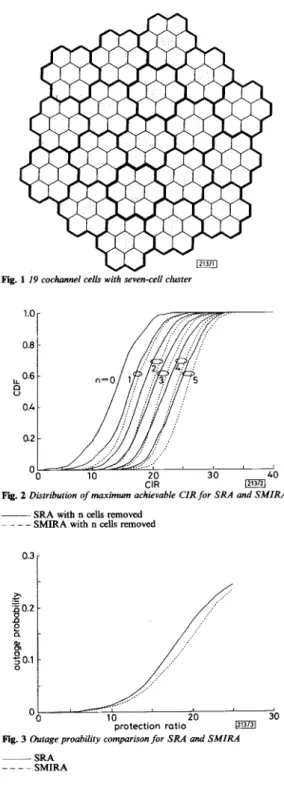
multiplications are negligible.Numerical results and discussion: Numerical results were obtained for a system containiig 19 cochannel cells that uses a seven-cell cluster (see Fig. I). All the values were obtained by means of Monte Carlo simulation for 500 independent configurations. In our study, we used o = 6 and v = 4.
196
M
Fig. 1 19 cochannel cells with seven-cell clustef
Fig. 2 Distribution of maximum achievable CIR for SRA and SMIRA
~ SRA with n cells removed
- _ _ _
SMIRA with n cells removed0.3
I
Fig. 3 Outage proability comparison for SRA and SMIRA
~ SRA
_ - - - SMIRA
Fig. 2 shows the maximum achievable CIR after a number of cells were removed using the SRA and the SMIRA algorithms. It can be seen that the SMIRA algorithm is consistently better than the SRA algorithm.
In
Fig. 3 we compare the outage probability. The improvement of SMIRA over SRA can be as high as 22% when the protection ratio is -15dB. When only one cell is removed, our examples show that the SMIRA algorithm removes the cell in an optimum way with probability 64.8% (324 out of500), whereas the SRA algorithm achieves probability 44% (220 out of 500). When two cells are removed, the probabilities for the
ELECTRONICS LETTERS 3rd February 1994 Vol. 30 No. 3
SMIRA algorithm and the SRA algorithm are 48.8 and 22.2%,
respectively. 0 IEE 1994
Electronics Letters Online No: I9940140
1.X. Lin (Institute of Electronics, National Chiao Tung University, Hsinchu, Taiwan 30035, Republic of China)
T.-H. Lee and Y.-T. Su (Department of Communications Engineering, National Chiao Tung University, Hsinchu, Taiwan 30035. Republic of China)
22 November I993
References
1 AEIN,J.M.: ‘Power balancing in systems employing frequency resuse’, COMSAT Tech. Rev., 1973, 3, (2), pp. 217-99
2 ZANDER, I.: ‘Performance of optimum transmitter power control in cellular radio systems’, IEEE Trans., 1992, VT-41, (I), pp. 5 7 4 2
N - l
v,,,
sinz = y(i) sin($-
m+
1)zI=m
N - 1
= y(m) s i n z
+
y(i) sin(i - m+
1)z i=m+1 N - I = y ( m ) s i n z + y(i)(2coszsin(i-m)z i=m+l-
sin(i - m-
1)z) N - 1 = y ( r n ) s i n z + ~ c o s zC
y ( i ) s i n ( i - m ) z ik,,,+l N - I= y (m) sin z
+
2 cos z Vm+l sin z - Vm+p sin z (2) N - lRecursive algorithm for the discrete cosine
Y ( k ) = y(z) cos(5
(22+
1))“=O
N - 1
transform with general lengths
L.-P.
Chau and W.-C. Siu
= y ( o ) c ~ s ( ~ )+
C y ( i ) C O S ( Z ( 2 i + l ) )% = I
Indexing terms: Discrete cosine transforms, Algorithm theory A novel VLSI algorithm for computing the discrete cosine transform of variable length is proposed. By using some mathematical techniques, any general length DCT can he
converted into a recursive equation and this structure can he
realised using software, hardware and VLSI techniques. The formulation is particularly suitable for the real-time computation of the D(JT and this algorithm can he implemented using regular and parallel VLSI structures, so that the computational complexity is greatly reduced. It can also he extended to implement a two-dimensional DCT in a straightfonvard way. Introduction: The discrete cosine transform is widely used in the area of image processing and other digital signal processing appli- cations. Hence, the search for fast algorithms for computing dedi- cated lengths of DCT
[ I 4 1
is an active area of research. However there has not been much work carried out on the computation of the transform of any length.In [7], Goertzel proposed an algorithm to evaluate a finite trigo-
nometric series and the algorithm requires only N multiplications and
-
2 N additions to obtain the results. This algorithm can easily be implemented to compute the discrete fourier transform and it has also been extended to calculate the DCT [8]. The advantage of this algorithm is its regular structure and parallelism, which make it suitable for implementation usingVLSI
techniques.We present a novel algorithm to convert the DCT into a more efficient recursive form, which is suitable for parallel computation and no permutation is required for the inputloutput sequences.
To obtain the time recursive transfer function of Y(k), we multiply both sides by sin x :
Y (k)
sin z =y(o) cos(5)
sin zN - 1
+
~ y ( i ) (cos(iz) cos( ;)sin z-sin(iz) sin( ;)sin z)1=1
=y(o) cos
(:)
sin z N-1+
y(i)((coszcos (:)-sinzsin(5))
sin(iz))i = l N-1
- y(i) ((sin(iz) cosz - cos(iz) s i n z ) cos *=I
=y(o) cos
(3)
sin zN-1
*=1
=y(o) cos
( 5 )
sin z=y(o) cos
(3)
sin zDerivation ofalgorithm: The DCT of a sequence ( y ( i ) : i = 0, 1, ..., sinz1/1 -cos(;)sinzVp
N-1) can be written as N - 1
Y ( k ) = C y ( i ) c o s ( & ( 2 i + l ) k ) (1) e o
f o r k = 0, 1,
...,
N - 1To introduce a time recursive kernel for the DCT, we define Hence, we have
v,
= y ( m ) + 2 c o s z V m + 1 -vm+z (3)We intend to obtain a simplified expression for the DCT, let x = &IN, then
N-1
= y(0)cos
( Z )
+
y ( i ) (cos(zi) cost=l
(5))
-
sin(z i ) sinAfter the above obvious steps, we finally obtain
Y
(k)
= y(0) cos($)
+
cos(Z)
VI - cos($)
Vz (5) From eqns. 3 and 5, we know that no complex multiplication is required during the recursive computation. Eqn. 5 is a discrete time recursive transfer function of finite duration sequence, y ( 9 , i = N - 1, N - 2, . .., 1, 0. As a consequence, Y(k) is obtained as theoutput of a finite impulse response system. Fig. 1 shows a recur- sive structure for the realisation of Y(k).
In the literature, not much work has been reported on the com- putation of the DCT using a recursive filter structure; we have only found one paper on this topic. One possible realisation [SI has been suggested recently, which uses the Goertzel [7] algorithm