Flow effect in the chiral-homeotropic liquid-crystal cell
Shu-Hsia Chen and Li-Yi Chen
Citation: Applied Physics Letters 75, 3491 (1999); doi: 10.1063/1.125365 View online: http://dx.doi.org/10.1063/1.125365
View Table of Contents: http://scitation.aip.org/content/aip/journal/apl/75/22?ver=pdfcov Published by the AIP Publishing
Articles you may be interested in
Electro-optic bistability in organosiloxane bimesogenic liquid crystals J. Appl. Phys. 99, 113517 (2006); 10.1063/1.2203391
Bistable chiral tilted-homeotropic nematic liquid crystal cells Appl. Phys. Lett. 85, 5511 (2004); 10.1063/1.1830681
Effects of carbon nanosolids on the electro-optical properties of a twisted nematic liquid-crystal host Appl. Phys. Lett. 85, 513 (2004); 10.1063/1.1771799
Wide viewing angle, homeotropic nematic liquid-crystal display controlled by effective field Appl. Phys. Lett. 73, 470 (1998); 10.1063/1.121903
Dynamic flow and switching bistability in twisted nematic liquid crystal cells Appl. Phys. Lett. 71, 596 (1997); 10.1063/1.119804
This article is copyrighted as indicated in the article. Reuse of AIP content is subject to the terms at: http://scitation.aip.org/termsconditions. Downloaded to IP: 140.113.38.11 On: Thu, 01 May 2014 08:15:34
Flow effect in the chiral-homeotropic liquid-crystal cell
Shu-Hsia Chena)and Li-Yi Chen
Institute of Electro-Optical Engineering, National Chiao Tung University, 1001 Ta Hsueh Road, Hsinchu 300, Taiwan, Republic of China
共Received 10 June 1999; accepted for publication 4 October 1999兲
We investigated the dynamics of the chiral-homeotropic liquid-crystal cell and found that the flow of liquid crystal causes an optical bounce after switching on a high applied voltage. We analyzed the behavior of the directors by computer simulation and found that the field-induced backflow effect results in the abnormal twist of the directors near the substrates. The abnormal twist slows down the rising speed of the chiral-homeotropic cell and produces an optical bounce during the rising period. Our results indicate that the backflow effect should be considered on the design of fast chiral-homeotropic liquid-crystal cells. The significant distinctions between this field-induced optical bounce and the well-known optical bounce of the twisted nematic liquid-crystal cell are also described in this letter. © 1999 American Institute of Physics.关S0003-6951共99兲04148-0兴
Liquid-crystal共LC兲 displays are widely used in modern human–machine interfaces. Recently, the homeotropic LC cell1has become an important direct-view display device. It can provide very wide viewing angle by using multidomain structure and compensation films.2 However, its voltage-transmittance curve depends on the wavelength strongly due to the phase retardation effect. The chiral-homeotropic liquid-crystal 共CHLC兲 cell3–5 which is homeotropic in the off-state and has a twisted director structure in the on-state, reduces the chromatic problem of the homeotropic cell. The twisted structure improves the achromatic characteristic of the voltage-transmittance curve and its field-off state can provide an excellent dark state as same as the pure homeo-tropic cell under crossed-polarizers condition. Besides, with suitable material, the CHLC cell could also be driven by low voltage.5 These make the CHLC cell an attractive mode for light valve and display applications. Although the static electro-optical properties of the CHLC cell have been stud-ied by several researchers,3–6 there is no information avail-able on the dynamics of the CHLC cell.
In the dynamic behavior of liquid crystal displays, the flow of LC could have important influence at certain circum-stances. For example, the well-known optical bounce phe-nomenon of the twisted nematic共TN兲 liquid crystal display 共LCD兲 which occurs after switching off a high applied volt-age is caused by the backflow effect.7,8It indicates that the interaction between the flow of LC and directors should be considered in the switching process of the TN LCD. The optical bounce phenomenon of the TN LCD was explained independently by van Doorn7and Berreman.8Both of them numerically solved the equation of motion which is deduced from Ericksen–Leslie theory using computers. Their results can match the observation of the experiments.
In this letter, we report our investigation on the dynam-ics of the CHLC cell. We found that, in the CHLC cell, the flow effect also caused the optical bounce phenomenon which was originally found in the TN cell. Usually, the back-flow effect was recognized that it has significant influence on
the dynamic behavior of LCDs in the decay period.7–9 How-ever, the field-induced optical bounce of the CHLC cell in-dicates the backflow effect should be considered in the rising period if the homeotropic to planar state transition takes place. We calculated the transient transmittance of the CHLC cell by computer simulation and the result agreed with the experimental observation. Our numerical results show the backflow caused the abnormal twist near the boundaries after switching on the applied voltage, and the disappearance pro-cess of the abnormal twist resulted in an optical bounce dur-ing the risdur-ing period. The distinctions between the optical bounces of the TN cell and the CHLC cell are described in this letter.
To measure the dynamic electro-optical properties of the CHLC cell, we made several samples. We used the indium– tin–oxide glass as the substrates and coated them with the poly-imide JALS-204 共from Japan Synthetic Rubber Co.兲 which is used to form the vertical alignment layers. The sub-strates were treated by a rubbing process to obtain a uniform domain. The angle between the rubbing directions of the top and the bottom substrates was ⫺90°. The cell gap d is 6.2
m. The liquid-crystal material is MLC-6608 共from Merck兲 which has negative dielectric anisotropy and we added about 0.25% S-811 in it as the chiral dopant in order to obtaining a stable twisted structure in the field-on state. The CHLC cell was put between two crossed polarizers and the rubbing di-rection of the front substrate was parallel to the transmission axis of the front polarizer. A 5 mW He–Ne laser with wave-length of 632.8 nm was used as the light source. The trans-mitted light was detected by a PIN diode. The CHLC cell was driven by square waves generated by an arbitrary func-tion generator. The transient transmittance detected by the PIN diode was observed and recorded by a digitizing oscil-loscope.
Figure 1 shows the measured transient transmittance of the CHLC cell. There is an obvious optical bounce共the val-ley兲 after switching on a high applied voltage 共7.0 V兲. Like the TN cell operating under crossed-polarizers condition, the optical bounce was exhibited as a valley but not a bounce. If we change the crossed polarizers to parallel, the
transmit-a兲Electronic mail: [email protected]
APPLIED PHYSICS LETTERS VOLUME 75, NUMBER 22 29 NOVEMBER 1999
3491
0003-6951/99/75(22)/3491/3/$15.00 © 1999 American Institute of Physics
This article is copyrighted as indicated in the article. Reuse of AIP content is subject to the terms at: http://scitation.aip.org/termsconditions. Downloaded to IP: 140.113.38.11 On: Thu, 01 May 2014 08:15:34
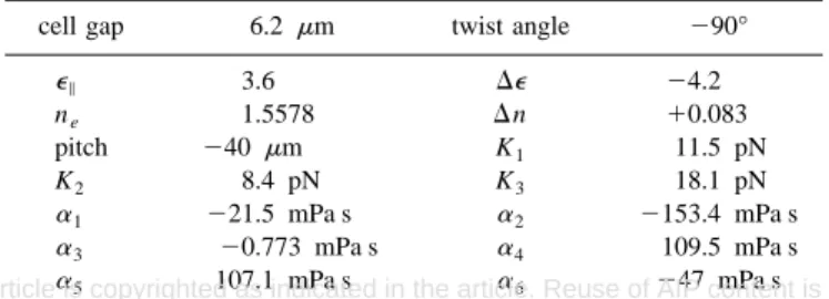
tance will be inverted and the valley will become a bounce. To simulate the dynamics behavior of the CHLC cell, we solved the equation of motion which was deduced from Ericksen–Leslie theory by the relaxation method and then we obtained the transient director distribution. The inertial terms in the equation were neglected in the simulation be-cause their influence is very small to compare with the vis-cous terms.7 After obtaining the transient director distribu-tion, we calculated the transmittance using Jones matrix method.10 Table I shows the parameters used in the simula-tion and these parameters were chosen as close as possible to our experiment. Due to the lack of the six Leslie coefficients of MLC-6608, these coefficients were taken from the value of MBBA.11
After performing the computer simulation, we obtained the transient transmittance of the CHLC cell. As shown in Fig. 2, the calculated transient transmittance curve which included the flow effect agrees with the experimental result qualitatively. The simulated optical bounce of the CHLC cell is slightly deeper than the measured one. This may be caused by the Leslie coefficients of MBBA being different from the MLC-6608’s. On the other hand, if the flow effect is ne-glected in the simulation, namely, considering only the rota-tion of the directors, the optical rising time will be shorter than both the case of including the flow effect and the ex-periment.
In order to understanding the mechanism of the field-induced optical bounce in the CHLC cell, we analyzed the transient director behavior by simulation. Figure 3 shows the
transient tilt angle distribution of the directors. The used pa-rameters are identical with that of Fig. 2. It can be found that after switching on the applied voltage, the tilt angle of the directors around the central part of the cell decreased faster than regions near the substrates. Since the rotation was in-duced by the external field and the orientational force due to polar anchoring is weaker here, these directors which were far from the substrate could be rotated more easily by the external field. This rotation of the directors in the central part drove the flow of LC due to the viscous interaction. After switching on the voltage, the tilt angle distribution took about 20 ms to reach its saturated value, that is, the tilt angle distribution was almost unchanged at 20 ms later, after the voltage was switched on. However, the simulated optical ris-ing time is about 80 ms. That means the variation of the twist angle distribution of the directors has crucial influence on the transient transmittance of the CHLC cell.
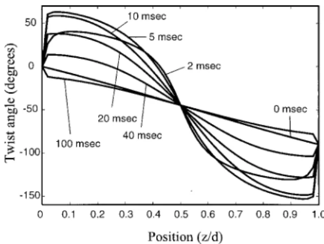
Figure 4 shows the calculated transient twist angle dis-tribution of the directors in the CHLC cell. After switching on the voltage, it can be found that the abnormal twist oc-curred near the boundaries, that is, the directors did not twist with their original trend 共left-handed twist兲. From the flow velocity distribution 共not shown兲, we found that the large gradient of the flow velocity caused this abnormal twist. The fast rotation of the director around the central part caused the
FIG. 1. Measured transient transmittance共upper trace兲 of the CHLC cell under crossed-polarizers condition. The lower trace is the applied wave forms, Vapplied⫽7.0 V. Note the optical bounce 共the valley兲 occurs in the
rising period.
TABLE I. The parameters used in the simulation. K1, K2, and K3 are
splay, twist, and bend elastic constant, respectively. The six Leslie coeffi-cients are taken from MBBA.
cell gap 6.2m twist angle ⫺90°
⑀储 3.6 ⌬⑀ ⫺4.2 ne 1.5578 ⌬n ⫹0.083 pitch ⫺40 m K1 11.5 pN K2 8.4 pN K3 18.1 pN ␣1 ⫺21.5 mPa s ␣2 ⫺153.4 mPa s ␣3 ⫺0.773 mPa s ␣4 109.5 mPa s ␣5 107.1 mPa s ␣6 ⫺47 mPa s
FIG. 2. Calculated transient transmittance of the CHLC cell. The applied voltage is switched on at t⫽0 (Vapplied⫽7.0 V).
FIG. 3. Calculated transient tilt angle distribution. z is the axis perpendicular to the substrates and d is the cell gap. The applied voltage is switched on at
t⫽0 (Vapplied⫽7.0 V). The tilt angle distribution reaches its saturated value
at 20 ms later after switching on the voltage.
3492 Appl. Phys. Lett., Vol. 75, No. 22, 29 November 1999 S.-H. Chen and L.-Y. Chen
This article is copyrighted as indicated in the article. Reuse of AIP content is subject to the terms at: http://scitation.aip.org/termsconditions. Downloaded to IP: 140.113.38.11 On: Thu, 01 May 2014 08:15:34
strong flow effect and resulted in the gradient of flow veloc-ity throughout the cell. The tilt angle near the boundaries is close to 90° because of the perpendicular alignment, thus the azimuthal angle of the directors near the boundaries can be influenced easily by the flow of LC. If we denote the title angle from the substrate by, the azimuthal共twist兲 angle by
, and z as the axis perpendicular to the substrate, the direc-tor can be expressed by n⫽(coscos,cossin,sin). The free energy density contributed by the variation of the azimuthal angle can be written as12
g
冉
d dz冊
⫽ 1 2关K2cos 4⫹K 3sin2cos2兴冉
d dz冊
2 , 共1兲where K2 and K3are the twist and the bend elastic constants
of the LC, respectively. From Eq.共1兲, it can be found that if the tilt angle is close to 90°, even though the variation of the azimuthal angle d/dz is very large, this drastic twist distortion just offers a minor contribution to the free energy density. Consequently, the azimuthal angle near the bound-aries can be influenced very easily by the backflow effect. As shown in Fig. 4, after switching on the voltage, the backflow effect caused the very large variation of the azimuthal angle near the boundaries. The directors close to the substrates did not influence the transmittance directly because of their high tilt angle but they changed the effective azimuthal boundary conditions of the cell. As a result, they dominated the twist structure of the directors throughout the cell. The disappear-ance process of the abnormal twist led the large variation of the twist angle distribution and formed the optical bounce in the rising period.
From our simulation, we found when the applied voltage is high, the disappearance of the abnormal twist takes much longer time then that the tilt angle distribution arrives at its saturated value 共see Figs. 3 and 4兲. This means the applied field has little influence on the disappearance process of the abnormal twist, and the disappearance of the abnormal twist is achieved almost by only the elastic force. Consequently, when the bounce appears, the optical rising time cannot be reduced effectively if we just increase the strength of the applied field.
The exhibits of these two optical bounces共the TN cell and the CHLC cell兲 seems to be similar but there are two
significant distinctions between them. First, the positions of the flow-induced opposite tilt or the abnormal twist are dif-ferent. In the TN case, most of the large distortion of the LC occurs near the substrates if the applied voltage is high. After switching off the voltage, the distortion causes the fast rota-tion of the director near the substrates and then the rotarota-tion induces the flow of LC. In the mid-plane, the gradient of the flow provides torque to the directors to drive them opposite tilt.7,8 Therefore the flow-induced opposite tilt is located at the central part of the TN cell. In the CHLC cell, the initial fast rotation of the directors is induced by the external field and as we mentioned above, after switching on a high ap-plied voltage, the occurring of the abnormal twist of the CHLC cell is close to the substrates but not the mid-plane of the cell.
Besides, the optical origins of these two bounce are also different. In the TN cell, the tilt angle of the directors in the mid-plane dominates the production of the optical bounce because the directors pass the axis perpendicular to the sub-strate twice. It causes the decreasing of the phase retardation locally when the tilt angle returns to 90° again and then it forms the optical bounce.7,8 On the other hand, the rising bounce of the CHLC cell occurs after most parts of the di-rectors reached their saturated tilt angle. It indicates that the forming of the rising optical bounce caused the variation of the twist angle distribution throughout the cell but not the variation of the tilt angle. This is the second distinction be-tween the TN case and the CHLC case.
In summary, we investigated flow effect on the dynam-ics of the CHLC cell and described the origin of the rising optical bounce phenomenon. It was found numerically that the field-induced backflow effect results in the optical bounce and the occurring of the abnormal twist has signifi-cant influence on the dynamic properties of the CHLC cell. We found the disappearance process of the abnormal twist slows down the optical response speed of the CHLC cell and we suggest that the flow effect should be considered in the design of fast response CHLC cells.
This work was partially supported by the National Sci-ence Council, R.O.C., under the Contract No. NSC-88-2212-M-009-030. The authors are indebted to Dr. Jong-Guang Wei of Chi-Mei Optoelectronics Co. and Professor Jin-Jei Wu of Soochow University for useful discussions. The poly-imides material support of Japan Synthetic Rubber Co. is greatly appreciated.
1
M. F. Schiekel and K. Fahrenschon, Appl. Phys. Lett. 19, 391共1971兲.
2
K. Ohmuro, S. Kataoka, T. Sasaki, and Y. Koike, Soc. Inform. Display Tech. Digest , 845共1997兲.
3D. de Rossi and J. Robert, J. Appl. Phys. 49, 1139共1978兲.
4S. W. Shu, S. T. Shin, and S. D. Lee, Appl. Phys. Lett. 68, 2819共1996兲. 5
S. T. Wu, C. S. Wu, and K. W. Lin, J. Appl. Phys. 82, 4795共1997兲.
6T. Takahashi, S. Saito, and T. Akahane, Jpn. J. Appl. Phys., Part 1 36,
3531共1997兲.
7C. Z. van Doorn, J. Appl. Phys. 46, 3738共1975兲. 8D. W. Berreman, J. Appl. Phys. 46, 3746共1975兲. 9
T. Z. Qian, Z. L. Xie, H. S. Kwok, and P. Sheng, Appl. Phys. Lett. 71, 596 共1997兲.
10R. C. Jones, J. Opt. Soc. Am. 32, 486共1942兲.
11H. Kneppe, F. Schneider, and N. K. Sharama, J. Chem. Phys. 77, 3203
共1982兲.
12
See, for example, P. G. de Genne and J. Prost, The Physics of Liquid
Crystals, 2nd ed.共Clarendon, Oxford, 1993兲.
FIG. 4. Calculated transient twist 共azimuthal兲 angle distribution. The ap-plied voltage is switched on at t⫽0 (Vapplied⫽7.0 V). Note the flow-induced
abnormal twist occurs near the substrates. The variation of the twist distri-bution results in an optical bounce during the rising period.
3493
Appl. Phys. Lett., Vol. 75, No. 22, 29 November 1999 S.-H. Chen and L.-Y. Chen
This article is copyrighted as indicated in the article. Reuse of AIP content is subject to the terms at: http://scitation.aip.org/termsconditions. Downloaded to IP: 140.113.38.11 On: Thu, 01 May 2014 08:15:34