國
立
交
通
大
學
電機學院 電信學程
碩
碩
碩
碩
士
士
士
士
論
論
論
論
文
文
文
文
IEEE 802.11 具備選擇性重傳和多次複製重傳
之組合式傳送方法
IEEE 802.11 Sectional Transmission Scheme with
Selective Repeat ARQ and Multi-copy ARQ
研究生:陳紹喜
指導教授:李程輝 教授
中
中
中
96 碩 士 論 文 IEEE 802.11 | 具 備製 選重 擇傳 性之 重組 傳合 和式 多傳 次送 複方 法 96 碩 士 論 文 IEEE 802.11 | 具 備製 選重 擇傳 性之 重組 傳合 和式 多傳 次送 複方 法 交 通 大 學 交 通 大 學 電 信 學 程 電 機 學 院 電 信 學 程 電 機 學 院 陳 紹 喜 陳 紹 喜 附件十三 書背打印規格範例 2.5 ㎝ 畢業︵ 民 學 國 年度︶ 2.5 ㎝ 1 ㎝ 校院 所名 著者 姓名 3 ㎝ 1 ㎝ 2 ㎝ 論文 題目
IEEE 802.11 具備選擇性重傳和多次複製重傳之組合式傳送方法
IEEE 802.11 Sectional Transmission Scheme with
Selective Repeat ARQ and Multi-copy ARQ
研 究 生:陳紹喜 Student:Shao-shi Chen 指導教授:李程輝 Advisor:Tsern-Huei Lee 國 立 交 通 大 學
電機學院 電信學程
碩 士 論 文 A ThesisSubmitted to College of Electrical and Computer Engineering National Chiao Tung University
in partial Fulfillment of the Requirements for the Degree of
Master of Science in
Communication Engineering June 2006
Hsinchu, Taiwan, Republic of China
國
立
交
通
大
學
國
國
立
立
交
交
通
通
大
大
學
學
國
立
交
通
大
學
博
博
博
博 碩 士 論 文 全 文 電 子 檔 著 作 權 授 權 書
碩 士 論 文 全 文 電 子 檔 著 作 權 授 權 書
碩 士 論 文 全 文 電 子 檔 著 作 權 授 權 書
碩 士 論 文 全 文 電 子 檔 著 作 權 授 權 書
(提供授權人裝訂於紙本論文書名頁之次頁用) 本授權書所授權之學位論文,為本人於國立交通大學(學院)電機資訊學 院碩士在職專班電信組, 95 學年度第一學期取得碩士學位之論文。 論文題目:IEEE 802.11 具備選擇性重傳和多次複製重傳組合式傳送方法 指導教授:李程輝 教授 ■ 同意 □不同意 本人茲將本著作,以非專屬、無償授權國立交通大學與台灣聯合大學系 統圖書館:基於推動讀者間「資源共享、互惠合作」之理念,與回饋社 會與學術研究之目的,國立交通大學及台灣聯合大學系統圖書館得不限 地域、時間與次數,以紙本、光碟或數位化等各種方法收錄、重製與利 用;於著作權法合理使用範圍內,讀者得進行線上檢索、閱覽、下載或 列印。 論文全文上載網路公開之範圍及時間: 本校及台灣聯合大學系統區域網路 ■中華民國 98 年 12 月 1 日公開 校外網際網路 ■中華民國 99 年 12 月 1 日公開 授 授授 授 權權權權 人:陳紹喜人:陳紹喜人:陳紹喜人:陳紹喜 親筆簽名: 親筆簽名:親筆簽名: 親筆簽名:________________________________________________________________________________________ 中華民國 中華民國中華民國 中華民國 96969696 年年年 年 11 11 月月月 月 3333 日日日 日
國
立
交
通
大
學
國
立
交
通
大
學
國
立
交
通
大
學
國
立
交
通
大
學
博 碩 士 紙 本 論 文 著 作 權 授 權 書
博 碩 士 紙 本 論 文 著 作 權 授 權 書
博 碩 士 紙 本 論 文 著 作 權 授 權 書
博 碩 士 紙 本 論 文 著 作 權 授 權 書
(提供授權人裝訂於全文電子檔授權書之次頁用) 本授權書所授權之學位論文,為本人於國立交通大學(學院)電機資訊 學院碩士在職專班電信組, 95 學年度第一學期取得碩士學位之論文。 論文題目:IEEE802.11 具備選擇性重傳和多次複製重傳組合式傳送方法 指導教授:李程輝 教授 ■ 同意 本人茲將本著作,以非專屬、無償授權國立交通大學,基於推動讀者 間「資源共享、互惠合作」之理念,與回饋社會與學術研究之目的, 國立交通大學圖書館得以紙本收錄、重製與利用;於著作權法合理使 用範圍內,讀者得進行閱覽或列印。 本論文為本人向經濟部智慧局申請專利(未申請者本條款請不予理會) 的附件之一,申請文號為:____________________,請將論文延至____ 年____月____日再公開。 授 授 授 授 權權權 權 人:陳紹喜人:陳紹喜人:陳紹喜 人:陳紹喜 親筆簽名: 親筆簽名: 親筆簽名: 親筆簽名:________________________________________________________________________________________ 中華民國 中華民國 中華民國 中華民國 96969696 年年年年 11 11 月月月月 333 3 日日日日
國家圖書館
國家圖書館
國家圖書館
國家圖書館博碩士論文電子檔案上網授權書
博碩士論文電子檔案上網授權書
博碩士論文電子檔案上網授權書
博碩士論文電子檔案上網授權書
ID:GT009267561 本授權書所授權之論文為授權人在國立交通大學(學院)電機資訊學院 碩士在職專班電信組, 95 學年度第一學期取得碩士學位之論文。 論文題目:IEEE 802.11 具備選擇性重傳和多次複製重傳組合式傳送方法 指導教授:李程輝 教授 茲同意將授權人擁有著作權之上列論文全文(含摘要),非專屬、無償 授權國家圖書館,不限地域、時間與次數,以微縮、光碟或其他各種數 位化方式將上列論文重製,並得將數位化之上列論文及論文電子檔以上 載網路方式,提供讀者基於個人非營利性質之線上檢索、閱覽、下載或 列印。 ※ 讀者基於非營利性質之線上檢索、閱覽、下載或列印上列論文,應依著作權法相關 規定辦理。 授權人:陳紹喜 授權人:陳紹喜 授權人:陳紹喜 授權人:陳紹喜 親筆簽名: 親筆簽名: 親筆簽名: 親筆簽名:____________________________________________________________ 民國 民國 民國 民國 99699666 年年年 年 11 月11月月 月 333 日3日日 日國 立 交 通 大 學
論 文 口 試 委 員 會 審 定 書
本校 電機學院碩士在職專班
電信 組 陳紹喜
君
所提論文:
(中文) IEEE 802.11 具備選擇性重傳和多次複製重傳之組合式傳送方法 (英文) IEEE 802.11 Sectional Transmission Scheme with
Selective Repeat ARQ and Multi-copy ARQ
合於碩士資格水準、業經本委員會評審認可。 口試委員: 指導教授: 班主任: 中 華 民 國 96 年 1 月 3 日
IEEE 802.11 具備選擇性重傳和多次複製重傳之組合式傳送方法
學生: 陳紹喜
指導教授: 李程輝 教授
國立交通大學電機資訊學院 電信學程(研究所) 碩士班
摘 要
當 IEEE 802.11 在一個錯誤位元率(BER)不斷上升的通訊通道中, 一個長 的訊框通常在傳送及接收方面會有比較低的成功機率. 而定義在 IEEE 802.11 MAC 中的 Fragmentation 正因上述狀況而存在, Fragmentation 雖然可 以改善封包遺失(packet loss)的問題, 但不幸的也同時使得封包延遲(packet delay)和通道的吞吐量(throughput)也大幅下降. 在此篇論文提出一個名為組 合式傳送方法, 該方法相容於舊有 IEEE 802.11 MAC 並且當系統工作在一 個帶有雜訊的通道中可同時改善封包遺失、封包延遲以及通道吞吐量. 相對 於謀體控制層(MAC-Level)中效率比較低的停等重傳(Stop-And-Wait ARQ), 在 組 合 式 方 法中 可 以 引 入 更 具 有 效 率之 訊 框 層 (Frame-Level) 的選擇性 (Selective Repeat)和多次複製(Multi-copy)重傳方法來改善重傳的效能. 最後 透過數據分析(Numerical Analysis)和模擬(Simulation)來證明當 IEEE 802.11 工作在帶有雜訊的通道中此方法可同時有效改善封包遺失、封包延遲和通 道吞吐量.IEEE 802.11 Sectional Transmission Scheme with
Selective Repeat ARQ and Multi-copy ARQ
Student: Shao-Shi Chen Advisor: Prof. Tsern-Huei Lee
Degree Program of Electrical and Computer Engineering
National Chiao Tung University
ABSTRACT
In the IEEE 802.11, a long frame will obtain a lower possibility to successfully transmit/receive when the channel Bit Error Rate (BER) is getting worst. And the Fragmentation, defined in the IEEE 802.11 MAC, is decided to solve the situation like this. Unfortunately, the Fragmentation not only improves the packet loss on the noisy channel, but also increases the packet delay and decreases the throughput. In this thesis, a new transmission scheme called Sectional Transmission, backward compatible with the IEEE 802.11 MAC, is proposed to improve the packet loss, packet delay and throughput at the same time when the IEEE 802.11 MAC is working on noisy channel. The more efficiency Frame-Level Auto Repeat reQuest (ARQ), like Selective Repeat ARQ and Multi-copy ARQ, can also be easily implemented on this scheme as compared with the inefficiency MAC-Level Stop-And-Wait ARQ in the legacy IEEE 802.11 MAC. Finally, both of numerical result and simulation result show that our proposed scheme efficiently improves the packet loss, packet delay and throughput at the same time when the IEEE 802.11 is working on noisy channel.
Acknowledgement
Firstly, I would like to acknowledge my advisor, Dr. Tsern-Huei Lee, for his forbearing guidance during my graduate study. Secondly, I also wish to profoundly thank my wife and my mother for their quietly devoted themselves to help me to absorbedly accomplish my thesis. Lastly, I have to deeply appreciate all people who contribute to the network simulator NCTUns.
Contents:
Chinese Abstract………. i English Abstract……….. ii List of Figure……….. v List of Table……… vi Acronym………. vii 1 Introduction……… 1 2 IEEE 802.11 MAC………. 4 2.1 DCF Procedure………. 5 2.2 Acknowledgment Procedure………. 6 2.3 Backoff Procedure………. 7 2.4 Fragmentation……… 8 3 Sectional Transmission……….. 93.1 New acknowledgement policy……….. 11
3.2 Frame-Level ARQ………. 12
3.3 FCS and ST-MPDU format decoding………... 14
3.4 Reception Flow………. 17
4 Numerical Analysis……… 18
4.1 Loss Probability of MSDU/MMPDU……… 18
4.2 Loss Probability of ST-MPDU………. 20
4.3 Numerical Results………. 22
5 Simulation Results………. 24
5.1 Loss Probability………. 25
5.2 Packet Delay……….. 27
6 Conclusions………. 31 References……….. 32
List of Figures:
Figure 1 Some IFS relationships and DCF timing……….…..(5)
Figure 2 Positive acknowledgement……….………(6)
Figure 3 Backoff procedure………..(7)
Figure 4 Fragmentation……..………...(8)
Figure 5 Fragmentation Burst………...(8)
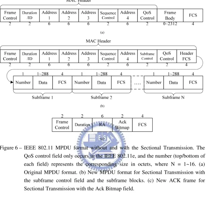
Figure 6 IEEE 802.11 MPDU format without and with the Sectional Transmission. The QoS control field only occurs in the IEEE 802.11e, and the number (top/bottom of each field) represents the corresponding size in octets, where N = 1~16. (a) Original MPDU format. (b) New MPDU format for Sectional Transmission with the subframe control field and the subframe blocks. (c) New ACK frame for Sectional Transmission with the Ack Bitmap field………(10)
Figure 7 The two-way frame exchange protocol under the Sectional Transmission, where “Hdr” means the MAC header and “SFn” means the subframe n……….(11)
Figure 8 Frame-Level ARQ Behavior, where "SFn" means the subframe n…………(12)
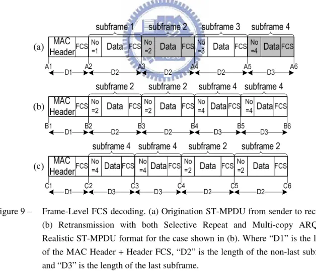
Figure 9 Frame-Level FCS decoding. (a) Origination ST-MPDU from sender to receiver. (b) Retransmission with both Selective Repeat and Multi-copy ARQ. (c) Realistic ST-MPDU format for the case shown in (b). Where "D1" is the length of the MAC Header + Header FCS, "D2" is the length of the non-last subframe and "D3" is the length of the last subframe………...(14)
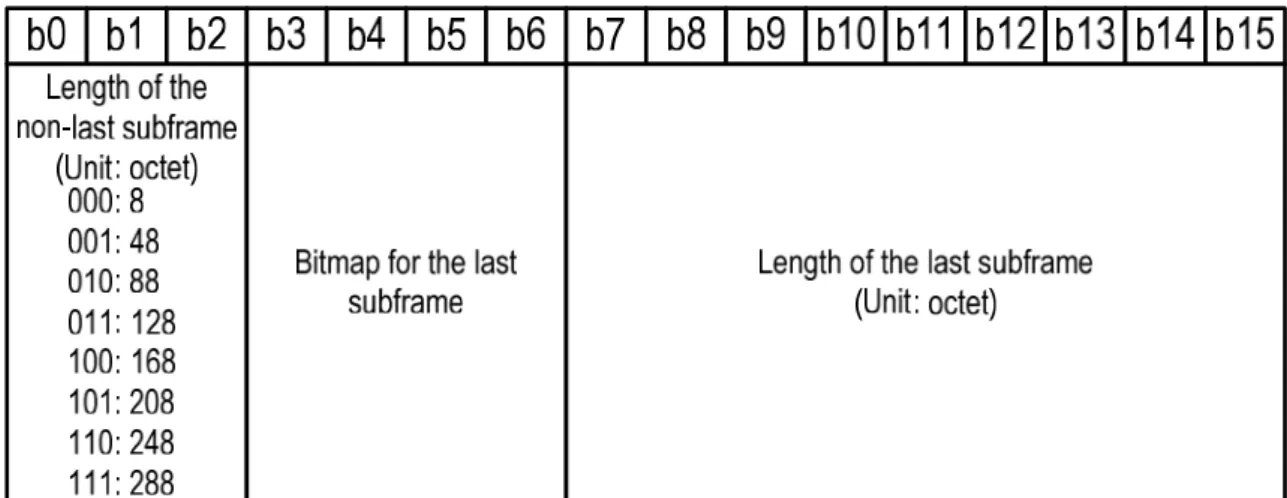
Figure 10 The partition of the Subframe Control Field……….(15)
Figure 11 Backward compatible ST-MPDU reception flow……….(17)
Figure 12 Loss Probability vs. Payload Size……….(23)
Figure 13 Loss Probability vs. Payload Size in UDP………(26)
Figure 14 Loss Probability vs. Payload Size in TCP………(26)
Figure 15 Packet Delay vs. Payload Size in UDP………(28)
Figure 16 Packet Delay vs. Payload Size in TCP………(28)
Figure 17 Throughput vs. Payload Size in UDP………..(30)
List of Tables:
Table 1 Five different thresholds, remainders and numbers of (ST-)MPDU for five different Payload Sizes………..(22)
Acronym:
ARQ: auto repeat request BER: bit error rate
CRC: cyclic redundancy check
DAR: dynamically adaptive retransmission DIFS: DCF inter-frame space
EIFS: error inter-frame space FCS: frame check sequence FEC: forward error correction
IEEE: institute of electrical and electronics engineers IFS: inter-frame space
MAC: media access control MCARQ: multi-copy ARQ
MMPDU: MAC management protocol data unit MPDU: MAC protocol data unit
MSDU: MAC service data unit
PLCP: physical layer convergence protocol QoS: quality of service
RS: reed solomon
SIFS: short inter-frame space SRARQ: selective repeat ARQ TCP: transport control protocol UDP: user data protocol
WEP: wired equivalent privacy WLAN: wireless local area network
Chapter 1
Introduction
1.1. Motivation
In recent years, wireless local area networks (WLANs), such as the IEEE 802.11, are going wider and wider popularity in many fields. Now, the IEEE 802.11 WLAN is an essential condition of those mobile/portable devices in this few years.
The IEEE 802.11 MAC [1] uses positive acknowledgements to inform the sender of successful delivery of data frame. It will be immediately (after Short Inter-Frame Space (SIFS) delay) sending an ACK frame back to the sender if the receiver received an error-free data frame. Else, the receiver will send nothing back to the sender. Then the sender must be waiting an Error Inter-Frame Space (EIFS) delay time to perform Stop-And-Wait [2] ARQ to retransmit the unacknowledged frame or dropping the unacknowledged frame immediately when the Short Retry Limit was been reached. There are two possible cases to cause an unacknowledged frame during the transmission. Firstly, the receiver didn’t receive a perfect data frame and not to send an ACK frame back to the sender. Secondly, the positive ACK frame was lost. When the channel BER is getting worst, the 1st case will frequently happen as compared with the 2nd case. Because the length of an ACK frame is only 14 octets and the length of a data frame up to thousands of octets. In another word, the higher BER may cause more packet loss. Of course, the packet delay will be increased and the throughput will be decreased at the same time, because the retransmission wastes both bandwidth and transmission time.
The IEEE 802.11 MAC may fragment directed MAC Service Data Unit (MSDU) or MAC Management Protocol Data Unit (MMPDU) into several MAC Protocol Data Unit (MPDU). Such operation, called Fragmentation [1], is designed to solve the 1st case (damaged data frame) as we talk above. A MPDU will obtain a higher possibility to pass through the noisy channel without any error, because the size of a MPDU is smaller than or equal to the size of a MSDU/MMPDU. But those redundancies (Preamble, PLCP header, MAC header, IFS and ACK frame) are also introduced into each MPDU. Although the fragmentation makes packet loss under control, both of the packet delay and
throughput are seriously degraded at the same time.
The related work in [3] considers a MAC-Level Forward Error Correction (FEC) scheme with retransmission combining to avoid the 1st case as we talk above. They split the frame body (payload) into several (N) small blocks, and do the Reed Solomon (RS) encode on each block & header. Thus, the new data frame is consisted of MAC-Header, header FEC redundancy, N*block and N*(data FEC redundancy). Receiver will perform the RS decode, if necessary, to try to correct each non-perfect block and header. If the whole data frame, all of the blocks and header, is completely perfect then the receiver sends an ACK frame back to sender to acknowledge the frame. Else, the receiver sends nothing back to sender and keeps those perfect blocks for the retransmission to combine. Therefore, the more retransmissions done by sender the fewer necessary blocks are needed to the receiver to combine a perfect data frame. Note that the length of an unacknowledged frame is never changed during those several retransmissions. Although the FEC (Reed Solomon code) strongly improves the packet loss, the architecture is much more complexity (iterative computation) and the large FEC redundancy (16 octets on each block and header) degrades the maximum throughput distinctness. The retransmission combining is simply and efficiency, but it could be better as long as it does not transmit the unnecessary block(s) during retransmission.
Another related work in [4] considers a Dynamically Adaptive Retransmission (DAR) scheme to improve the packet loss when the 2nd case (ACK frame loss) is occurred. But the improvement is indistinctness, because of the ACK frame is too small to obviously degrade the packet loss.
In this thesis, we consider a Sectional Transmission scheme to avoid the 1st case (damaged data frame) as we talk above. Sectional Transmission scheme performs a flexible data frame format for those well-known error-control schemes (like FEC and ARQ). In this scheme, we split the original frame body (payload) up into 16 subframes; all of the subframes and MAC header perform a Frame Check Sequence (FCS) separately. And the FCS is simple as the original (32-bit CRC). Additionally, the subframe number (1 octet) is appended in front of echo subframe for indication. Therefore, each subframe is fully independent of the outer (original) FCS, so they can perform FEC and ARQ inside each sub-frame separately (call Frame-Level). As compare with the [3], we only introduce 5 octets in each sub-frame and the Error-Detection code is simple CRC. Especially, both of the Selective Repeat ARQ and Multi-copy ARQ can be easily implemented on the Frame-Level at this scheme. Finally, we prove that the packet loss, packet delay and throughput will be improved at the same time
when the channel BER is getting worst via numerical analysis and simulation.
1.2. Outline
The rest of this thesis is organized as follows. A brief introduction of the IEEE 802.11 MAC is made at Chapter 2. In Chapter 3 our Sectional Transmission scheme will be described in detail. The numerical analysis and simulation results are presented in Chapter 4 and Chapter 5. Finally conclusions will be made in Chapter 6.
Chapter 2
IEEE 802.11 MAC
In this Chapter, we consider an infrastructural basic service set (BSS) which is consisted of one Access Point (AP) and a number of Stations (STAs) associated to the AP. Those STAs communicate only via the AP even the communication between two STAs. The carrier sense multiple access (CSMA) is used in the IEEE 802.11 MAC, it means that every sender (AP/STA) needs to sense the channel before sending a packet. Thus, the collision avoidance (CA) must be implemented in every STA/AP due to the decision of sending packet is distributed in all STAs/AP.
The IEEE 802.11 MAC receives a MAC service data unit (MSDU) or a MAC management protocol data unit (MMPDU) from the upper layer, and sends one or more MAC protocol data units (MPDUs) to the lower layer. If the length of a directed MSDU or a directed MMPDU is greater than aFragmentationThreshold, then the MSDU/MMPDU shall be fragmented into several MPDUs.
The problem of hidden node in the IEEE 802.11 MAC is solved via exchanging short control frames [request to send (RTS) and clear to send (CTS) frames] between AP and STA. The RTS announces that the sender prepares to transmit a packet and those stations near to the sender will not attempt to transmit any packet after hearing a RTS, and the CTS announces that the receiver prepares to receive a packet and those stations near to the receiver will not attempt to transmit any packet too after hearing a CTS. Thus, all stations near to both sender and receiver will not send any packet until the transmission between sender and receiver is finished.
2.1. DCF Access Procedure
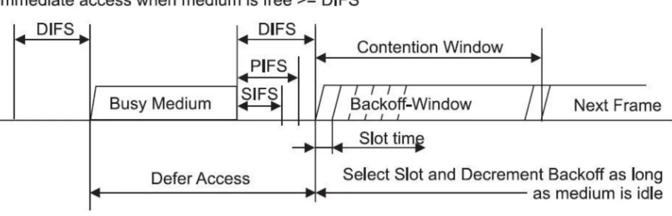
The time interval between frames is called Inter-Frame Space (IFS). There are four IFSs in the IEEE 802.11 MAC as shown in following listing:
a) Short Inter-Frame Space (SIFS).
b) PCF (i.e., Point Coordination Function) Inter-Frame Space (PIFS).
c) DCF (i.e., Distribution Coordination Function) Inter-Frame Space (DIFS). d) Extended/Error Inter-Frame Space (EIFS).
The SIFS is defined at section 10.4.3.2 of [1], and the DIFS is equal to one SIFS plus one Slot Time, where the Slot Time is also defined at the section 10.4.3.2 too. The DIFS is given by DIFS = SIFS + 2*SlotTime and the EIFS defined at section 9.2.10 of [1].
The basic protocol in the IEEE 802.11 MAC is referred to as the DCF, which operates as a listen-before-talk or CSMA/CA scheme. The sender senses (“listen”) the medium as idle for a DIFS time after Backoff procedure (described at section 2.3) is finished, when the sender attempts to send (“talk”) a MPDU. The sender defers its access until the medium becomes idle for a DIFS time, after it senses the medium that is busy. And the receiver immediately (after a SIFS time delay) sends an ACK frame back to the sender to acknowledge the received MPDU, after the receiver receives a MPDU successfully. The following figure shows those relationships we talk above.
2.2. Acknowledgment Procedure
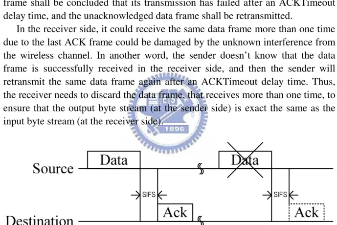
The positive acknowledgement is performed in the IEEE 802.11 MAC, and such scheme ensures the reliability of the communication between two stations. The receiver immediately (after a SIFS delay time) sends an ACK frame back to the sender to acknowledge the received frame when the data frame, from the sender, is successfully received (i.e., FCS is correct) by the receiver and such frame needs to be acknowledged. As shown in figure 2, if the receiver receives a data frame that needs to be acknowledged and its FCS is incorrect (after decode), then the receiver sends nothing back to the sender. In the sender, such data frame shall be concluded that its transmission has failed after an ACKTimeout delay time, and the unacknowledged data frame shall be retransmitted.
In the receiver side, it could receive the same data frame more than one time due to the last ACK frame could be damaged by the unknown interference from the wireless channel. In another word, the sender doesn’t know that the data frame is successfully received in the receiver side, and then the sender will retransmit the same data frame again after an ACKTimeout delay time. Thus, the receiver needs to discard the data frame, that receives more than one time, to ensure that the output byte stream (at the sender side) is exact the same as the input byte stream (at the receiver side).
2.3. Backoff Procedure
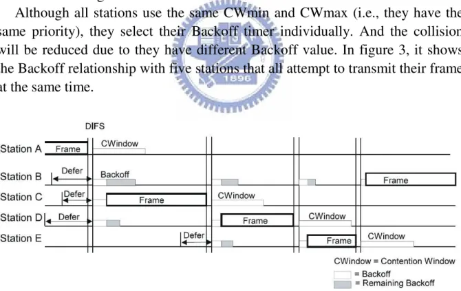
In the IEEE 802.11 MAC, all stations have to maintain a Backoff timer for the contention, such contention (period) is called Contention Window (CW). The CW is set to the minimum value CWmin after each successful transmission, and the value of the Backoff timer is uniformly selected from zero to CW which is a multiple of a Slot Time. The Backoff timer doubles itself, until the CW reaches the maximum value CWmax, after collision. Both CWmin and CWmax are defined at section 10.4.3.2 of [1].
Every station that attempts to transmit a MPDU must senses the medium that should be idle for a DIFS time, and its Backoff timer must be counted down (if the medium still be idle after a DIFS time) to zero. Once the medium is busy during the Backoff timer counting down, the station stops downcounting the Backoff timer and defers (instead of reset) itself until the medium becomes idle for a DIFS time again.
Although all stations use the same CWmin and CWmax (i.e., they have the same priority), they select their Backoff timer individually. And the collision will be reduced due to they have different Backoff value. In figure 3, it shows the Backoff relationship with five stations that all attempt to transmit their frame at the same time.
2.4 Fragmentation
The IEEE 802.11 MAC may fragment directed MAC Service Data Unit (MSDU) or MAC Management Protocol Data Unit (MMPDU) into several MAC Protocol Data Unit (MPDU) as shown in figure 4, if the length of MSDU or MMPDU is greater than the parameter aFragmentationThreshold. Note that every MSDU/MMPDU will not be fragmented, even its length is greater than the aFragmentationThreshold, when it is a multicast packet. Each fragmented MPDU will be transmitted separately, and shall be retransmitted when it is unacknowledged. At the receiver side, it shall reassemble all fragmented MPDUs into a MSDU/MMPDU according to the information that included in each fragmented MPDU.
Figure 4 – Fragmentation
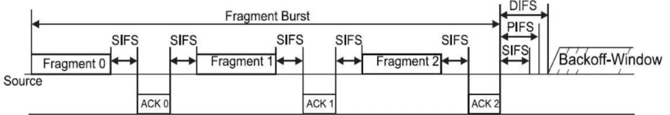
In the DCF, those fragmented MPDUs are sent as a burst period called Fragment Burst (as shown in figure 5). The receiver sends an ACK frame back to the sender to acknowledge the incoming MPDU after a SIFS when it receives an error-free MPDU, and the sender will send the next fragmented MPDU after a SIFS when the last outgoing MPDU is acknowledged by an error-free ACK frame, such circle will be repeated until all fragmented MPDUs is successfully transmitted or any failed transmission interrupt the Fragment Burst.
Chapter 3
Sectional Transmission
Figure 6(a) shows the original IEEE 802.11 MPDU format. The minimum length of the frame body is 0 octets and the maximum is 2312 octets when the Wired Equivalent Privacy (WEP) is employed. In the IEEE 802.11 MAC, it will cause retransmission/discard (i.e., packet loss) even if only one error-bit was found (i.e., FCS check fail) inside the MPDU. And the retransmission/discard will occur frequently when the BER of the transmission channel goes worse and worse. It will be the worst, especially, when the size of the frame body is maximum amount. No doubt the fragmentation, defined in IEEE 802.11 MAC, improves the packet loss (the 1st case as we talk in Chapter 2), however it introduces 3 disadvantages. Firstly, it leads a large redundancy (MAC header and FCS) into each fragmented MPDU, but the MSDU/MMPDU takes only one MAC header and one FCS. Secondly, those fragmented MPDUs all need to be acknowledged separately, and perform the Backoff procedure when the Fragment Burst was interrupted by any one of damaged MPDU or damaged ACK frame. Lastly, the Fragment Burst needs more SIFS. According to those disadvantages, we can easily understand that both of the packet delay and throughput are terribly degraded when the fragmentation is working. Of course the packet loss is improved because the length of MPDU is smaller than that of MSDU/MMPDU.
Figure 6(b) shows the new MPDU format for the Sectional Transmission that we proposed. The original frame body is split up into N subframes, where N = 1~16. Each subframe is packed with one subframe number (1 octet) and one subframe FCS (4 octets). The subframe number indicates which piece of the original frame body inside the subframe data field, and the subframe FCS performs the Error Detection (32-bit CRC) through the subframe number and subframe data (1~288 octets) field. There are two new fields in the MAC header, one is subframe control field (2 octets), and the other is header FCS field (4 octets). The header FCS performs the Error Detection (32-bit CRC) for the whole MAC header, and the subframe control field provides the necessary information about MPDU format (for receiver decoding).
(a)
(b)
(c)
Figure 6 – IEEE 802.11 MPDU format without and with the Sectional Transmission. The QoS control field only occurs in the IEEE 802.11e, and the number (top/bottom of each field) represents the corresponding size in octets, where N = 1~16. (a) Original MPDU format. (b) New MPDU format for Sectional Transmission with the subframe control field and the subframe blocks. (c) New ACK frame for Sectional Transmission with the Ack Bitmap field.
3.1. New acknowledgement policy
A new ACK frame for Sectional Transmission was depicted in Figure 6(c). The included Ack Bitmap field (2 octets/16 bits, because of Nmax=16) is the only
difference in format between the original ACK frame and the Sectional Transmission (ST) ACK frame. Such Ack Bitmap field informs the sender about which subframe is “no good”, and the sender performs the subframe (i.e., Frame-Level) retransmission according to the subframe status from Ack Bitmap field. In the IEEE 802.11 MAC, there is no need to send an ACK frame back to the sender when the MPDU is not perfect. But the receiver, in the Sectional Transmission Scheme, responses in three cases:
1) The receiver responses nothing after checking header FCS is fail.
2) The receiver responses an ACK frame when the whole ST-MPDU (i.e., Sectional Transmission MPDU) is completely correct.
3) The receiver responses a ST-ACK frame (i.e., Sectional Transmission ACK frame) to inform the sender of which subframe still needs to be retransmitted.
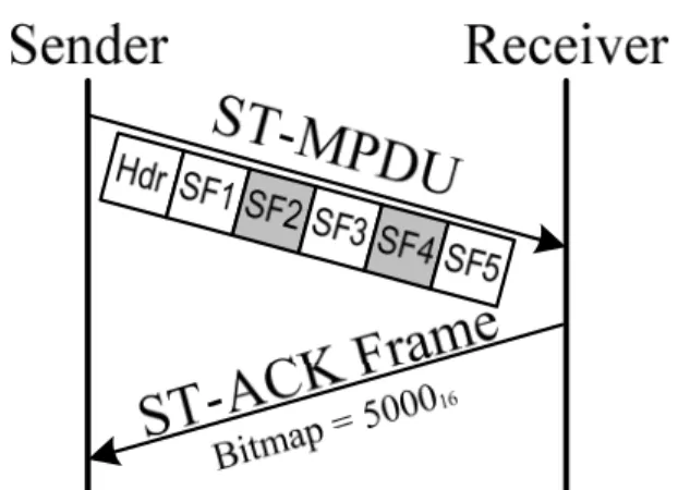
For example, the sender transmits a ST-MPDU with 5 subframes to the receiver (as show in Figure 7), but both subframe 2 and subframe 4 are not correctly received. Therefore, the receiver sends a ST-ACK frame (case 3 as we talk above) back to the sender, and set both 2nd & 4th bit of the Ack Bitmap field (i.e., 01010000000000002/500016) to inform the sender of the retransmission of both
subframe 2 and 4.
Figure 7 – The two-way frame exchange protocol under the Sectional Transmission, where “Hdr” means the MAC header and “SFn” means the subframe n.
3.2. Frame-Level ARQ
Figure 8 – Frame-Level ARQ Behavior, where “SFn” means the subframe n.
The purpose of ST-ACK frame is not only to avoid the EIFS when the sender doesn’t receive the expected ACK frame but also to inform the sender of the subframe status of the ST-MPDU. According to the independent subframe format and the subframe status from ST-ACK frame, we introduce both more efficient Selective Repeat ARQ [2,5,6] and more reliable Multi-copy ARQ [6] into the Sectional Transmission Scheme. As the view of MAC-Level, it is performing the same Stop-And-Wait ARQ no matter the Sectional Transmission is employed or not. In another view of Frame-Level, we can perform the Selective Repeat ARQ and the Multi-copy ARQ under the MAC-Level Stop-And-Wait ARQ if and only if the Sectional Transmission is implemented. For example, figure 8(a) shows the origination ST-MPDU sent from sender to receiver. Unfortunately, those subframes {2, 4, 6} was damaged by the unknown interference. Receiver will notice the sender which subframes to be retransmitted are needed via a ST-ACK frame. Whatever the Sectional Transmission is performed, the sender retransmits the same ST-MPDU until it is completely received by receiver (i.e., MAC-Level Stop-And-Wait ARQ). In the MAC-Level, there is nothing we can do except the Stop-And-Wait ARQ. However there is something we can do in the Frame-Level; we can only retransmit the necessary subframe [i.e., Selective Repeat ARQ as show in figure 8(b)] to improve the throughput and the packet delay and/or retransmit the subframe more than one time in a single ST-MPDU [i.e., Multi-copy ARQ as show in figure 8(c)] to improve the packet loss and the packet delay. Of course, the receiver must keep the error-free subframe(s) for the retransmission to
combine a perfect ST-MPDU. Base on the Frame-Level ARQ, the length of the retransmitted ST-MPDU is going smaller and smaller when the retransmission time is getting more and more. Hence, the packet loss will be decreased, the packet delay will be decreased and the throughput will be increased when the Frame-Level ARQ is employed. Note that the Multi-copy ARQ can be performed even at the first transmission of ST-MPDU not only the retransmission of ST-MPDU.
3.3. FCS and ST-MPDU format decoding
Every FSC in the ST-MPDU is performing the same Error Detection code (i.e., 32-bit CRC) as the definition on section 7.1.3.6 of [1]. The initial remainder must be preset to all 1’s before the field’s calculation, and results error-free in a unique nonzero remainder value. In the IEEE 802.11 MAC, the CRC Remainder Initialization (CRCRI) is easy to be finished, because it occurs only one FCS and the position of the CRCRI is the begin of the MPDU. But there is more critical to finish more than one CRCRI in a ST-MPDU, because of the number of FCS is up to 17 (Header FCS + subframe FCS). Each FCS of a ST-MPDU must do their own CRCRI separately, so there are (up to) 17 positions needed to be located. Figure 9(a) shows an origination ST-MPDU with 4 subframes. Because the length of a ST-MPDU is not divided without remainder all the time, thus the length of the last subframe (as the subframe 4 shown in Figure 9a) is usually smaller than the non-last subframe (as the subframe 1~3 shown in Figure 9a).
Figure 9 – Frame-Level FCS decoding. (a) Origination ST-MPDU from sender to receiver. (b) Retransmission with both Selective Repeat and Multi-copy ARQ. (c) Realistic ST-MPDU format for the case shown in (b). Where “D1” is the length of the MAC Header + Header FCS, “D2” is the length of the non-last subframe and “D3” is the length of the last subframe.
[as show in Figure 9(a)] to correctly perform the Error Detection (FCS/32-bit CRC). So, the length D1 and D2 must be given. Figure 9(b) shows a retransmitted ST-MPDU that retransmits subframe 2 and 4 under both Selective Repeat and Multi-copy (Double) ARQ. At this case, the CRCRI must be done at the point B1, B2, B3, B4 and B5 [as show in Figure (9b)]. Not only the length D1, D2 and D3 must be given to finish the CRCRI, but also the location of the last subframe (in the subframe sequence) must be given too. As the case shown in figure 9(b), the receiver can’t determine where the point B5, because the distance between B4 and B5 could be D2 or D3. Hence, the location of the last subframe must be given to notify the receiver where the D3 located. Therefore, the length of the non-last subframe, the length of the last subframe and the location of the last subframe must be given after Header FCS field, because the length of the MAC Header and the length of the Header FCS are known (constant) number. Figure 9(c) shows the realistic ST-MPDU format when the case as shown in figure 9(b) is occurred. Actually, the last subframe must be placed between the 1st subframe slot and the 4th subframe slot after Header FCS (i.e., it will not be more than 4 last subframes present in a ST-MPDU).
Figure 10 – The partition of the Subframe Control Field.
Figure 10 shows the partition of the Subframe Control Field (located in the MAC Header). The Subframe Control Field, total 2 octets, provides three important messages for the receiver to recognize the ST-MPDU format. The first is the length of the non-last subframe, and it is located in bit 0~2 (total 3 bits). There are only eight numbers for the length of the non-last subframe. For example: if 0112 present in bit 0~2, it means the length of the non-last subframe
is 128 octets. Thus, the maximum MSDU size allowed in ST-MPDU is 288 * 16 = 4608 octets, but the limitation could be broken at the coexistence between
Fragmentation and Sectional Transmission. The second message is the location of the last subframe, and it is located in bit 3~6 (total 4 bits). The last subframe will not be inserted more than 4 times in a ST-MPDU, and they must be located between the 1st subframe slot and the 4th subframe slot. And those bit 3~6, located in the Subframe Control field, indicate which subframe slot is the last subframe. For example: if 01012 present in bit 3~6, it means both the 2
nd
subframe slot and the 4th subframe slot are the last subframe, and both the 1st subframe slot and the 3rd subframe slot are the non-last subframe. The third message is the length of the last subframe, and it is located in bit 7~15 (total 9 bits). Finally, the necessary information for the receiver to organize the ST-MPDU is completely provided in the Subframe Control field, and the Frame-Level ARQ will be fully implemented in Sectional Transmission.
3.4. Reception Flow
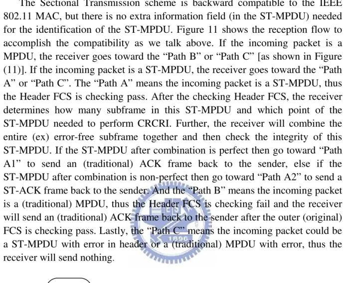
The Sectional Transmission scheme is backward compatible to the IEEE 802.11 MAC, but there is no extra information field (in the ST-MPDU) needed for the identification of the ST-MPDU. Figure 11 shows the reception flow to accomplish the compatibility as we talk above. If the incoming packet is a MPDU, the receiver goes toward the “Path B” or “Path C” [as shown in Figure (11)]. If the incoming packet is a ST-MPDU, the receiver goes toward the “Path A” or “Path C”. The “Path A” means the incoming packet is a ST-MPDU, thus the Header FCS is checking pass. After the checking Header FCS, the receiver determines how many subframe in this ST-MPDU and which point of the ST-MPDU needed to perform CRCRI. Further, the receiver will combine the entire (ex) error-free subframe together and then check the integrity of this ST-MPDU. If the ST-MPDU after combination is perfect then go toward “Path A1” to send an (traditional) ACK frame back to the sender, else if the ST-MPDU after combination is non-perfect then go toward “Path A2” to send a ST-ACK frame back to the sender. And the “Path B” means the incoming packet is a (traditional) MPDU, thus the Header FCS is checking fail and the receiver will send an (traditional) ACK frame back to the sender after the outer (original) FCS is checking pass. Lastly, the “Path C” means the incoming packet could be a ST-MPDU with error in header or a (traditional) MPDU with error, thus the receiver will send nothing.
Chapter 4
Numerical Analysis
The analysis of the packet loss probability is based on those given in [3]. In this numerical analysis, we assume that the channel model is uniform distribution and modeling all channels in BER. And the Fragmentation ignores the limitation of the aMaxTransmitMSDULifeTime, defined in section 9.4 of [1]. Although those assumptions are making here, but we believe that our analysis results will show the same trend with the realistic (simulation) results.
4.1. Loss Probability of MSDU/MMPDU
Let Pb denotes the bit error rate, and the byte error rate
8 ) 1 ( 1 b B P P = − − ,
and the error probability Pblk of a block in length of l bytes is
l B blk l P
P ( )=1−(1− ) . Hence, the error probability Pferr of a MPDU is given by
) 4 24 ( + + = P PayloadSize Pferr blk , (1)
where PayloadSize is the length of the frame body (payload) and the constants 24 and 4 denote the length of MAC Header and the length of FCS [as shown in figure 6(a)]. In the IEEE 802.11 MAC, it does have a retry limit for every MPDU, if the retransmission times over the retry limit then the sender discard the MPDU instead of the retransmission. LetRdenotes the retransmission times,
and the probability of a MPDU successfully received by the receiver at the
th − R transmission is given by ) 1 ( ) ( ferr R 1 ferr org fok P P P = − − . (2)
Finally, the loss probability of a MSDU/MMPDU within R
(re)transmissions is obtained by
∑
= − = R i org fok org loss R P i P 1 ) ( 1 ) ( . (3)MSDU/MMPDU into several MPDU that the length is not greater than aFragmentThreshold. The length of a fragmented MPDU shall be an equal number of octets (bytes) for all fragmented MPDUs except the last, which may be smaller [1].
)
(
aFragmentT
hreshold
P
P
fferr=
blk (4)))
1
(
*
(
−
−
=
P
PayloadSiz
e
aFragmentT
hreshold
N
P
lferr blk (5)Equation (4) and (5) show the error probability for the fragmented MPDU and the last fragmented MPDU, where N is the number of fragmented MPDU after fragmenting a MSDU/MMPDU.
∑
= − − = R i ffer i ffer frm R P P P 1 1(1 ) ) ( ) ( (6)∑
= − − = R i lfer i lfer lfrm R P P P 1 1 ) 1 ( ) ( ) ( (7)Equation (6) shows the probability of a fragmented MPDU successfully received by the receiver within R (re)transmissions, and equation (7) shows the probability of the last fragmented MPDU successfully received by the receiver within R (re)transmissions. Lastly, the loss probability Plossfrg(R) of a MSDU/
MMPDU, with the Fragmentation, within R (re)trans-missions is obtained by
)
(
)
(
1
)
(
R
P
R
1P
R
P
lossfrg=
−
frm N− lfrm (8)4.2. Loss Probability of ST-MPDU
In the Sectional Transmission, the receiver will ignore the received ST-MPDU if any reception error is found inside the MAC header or header FCS, because of the ST-MPDU format couldn’t be decoded. Just like the Fragmentation, the length of a subframe shall be an equal number of bytes for all subframes except the last, which may be smaller. Let
P
hdr denotes the errorprobability of the MAC header of the ST-MPDU that is given by
)
30
(
blk hdr
P
P
=
(28 octets in MPDU and 30 octets in ST-MPDU). Equation (9)is an approximation equation for the error probability of a subframe,
[
]
kblk k
sub
P
SubframeSi
ze
P
=
(
1
+
+
4
)
(9)where the k means how many times a subframe, needed to be retransmitted, will be retransmitted in a single Multi-copy ARQ, and the SubframeSize is the mean length of all subframes. Let N denotes the number of subframes after splitting a MSDU/MMPDU then the mean length of all subframes is given by
N
e
PayloadSiz
ze
SubframeSi
=
/
(10) Thus, the probability of i subframes, out of j subframes, are incorrect is given byi j k sub i k sub k E
P
P
i
j
j
i
P
−
−
=
(
)
(
1
)
)
|
(
, (11)Therefore, the probability of a subframe that successfully receives at the th − R (re)transmission is given by
)
|
0
(
)
|
(
)...
|
(
)
|
(
...
)
(
)
1
(
1
)
|
0
(
)
1
(
)
(
0
1
)
(
1 , 1 , 1 2 , 1 1 , 1 1 1 1 1 1 1 1 , 1 1 1 2 1 i E i i k E k E E N n n n n n i R hdr i hdr R i E hdr R hdr ST fokn
P
n
n
P
n
n
P
N
n
P
P
P
i
R
N
P
P
P
R
R
P
i i − = = = − − + − = −∑ ∑ ∑
∑
−−
−
+
−
−
=
(12)where the
n
x means the number of the incorrect subframe after xtransmissions. For example:
R
=
3
∑ ∑
∑
= = = − − + − − + − − = 2 1 2 1 1 1 2 , 1 2 , 1 1 , 0 2 1 1 , 1 1 , 1 1 1 , 2 0 ) | 0 ( ) | ( ) | ( ) 1 ( ) ( ) 1 ( 2 2 ) | 0 ( ) | ( ) 1 ( ) ( ) 1 ( 1 2 ) | 0 ( ) 1 ( ) ( ) 1 ( 0 2 ) 3 ( n n N n k E k E E hdr hdr hdr N n k E E hdr hdr hdr E hdr hdr hdr ST fok n P n n P N n P P P P n P N n P P P P N P P P P PEventually, the loss probability PlossST(R) of a MSDU /MMPDU, with both
Selective Repeat and Multi-copy ARQ under the Sectional Transmission, within
R (re)transmissions is obtained by
∑
=−
=
R i ST fok ST lossR
P
i
P
1)
(
1
)
(
(13)4.3. Numerical Results
Figure 12 shows those packet loss probabilities of 12 cases, and those cases could be classified in following four groups:
1) “DCF”: the MPDU without Fragmentation using equation (3). 2) “Fragment”: the MPDU with Fragmentation using equation (8).
3) “SRARQ”: the ST-MPDU (i.e., Sectional Trans-mission is enabled) with Selective Repeat ARQ using equation (13) andk =1.
4) “MCARQ”: the ST-MPDU (i.e., Sectional Transmission is enabled) with both Selective Repeat ARQ and Multi-copy ARQ using equation (13) andk =2
And the number with parts per million (ppm) denotes the channel BER. Note that, all charts in this thesis depict the same form like this. For example: case “100ppm-SRARQ” means the result comes from equation (13) (i.e., the third group shown above) and the channel BER is 100ppm. The aFragmenThreshold
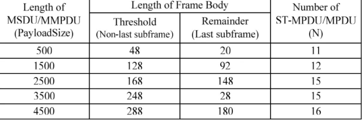
in equation (8) is the sum of (Threshold + MAC header + FCS), i.e., Threshold + 24 + 4, where the Threshold is shown in Table 1, and the number of fragmented MPDU (N) in equation (8) and the number of subframe (N) in equation (13) are referred to the same row (N) shown in Table 1, and the Retry Limit (R) is 7 in all cases.
Table 1
Five different thresholds, remainders and numbers of (ST-)MPDU for five different Payload Sizes
5000 1,500 2,500 3,500 4,500 0.1 0.2 0.3 0.4 0.5 0.6 0.7 0.8 0.9 1
Payload Size (Byte)
L o s s P ro b a b il it y 50ppm-DCF 50ppm-Fragment 50ppm-SRARQ 50ppm-MCARQ 100ppm-DCF 100ppm-Fragment 100ppm-SRARQ 100ppm-MCARQ 500ppm-DCF 500ppm-Fragment 500ppm-SRARQ 500ppm-MCARQ
Figure 12 – Loss Probability vs. Payload Size.
We firstly observe the first group (i.e., without Fragmentation and Sectional Transmission) under 3 different channel BERs as shown in figure 12, such 3 curves are the worst performance under there own channel BER due to no Fragmentation and Sectional Transmission. They show that both the Payload Size and the channel BER will significantly increase the loss probability when either the channel BER or the Payload Size is increased. Hence, we can easily imagine that both packet delay and throughput will be rapidly degraded when both channel BER and Payload Size is large. Now, we observe the rest of group at the same time, all of them are obviously improved the loss probability even those loss probabilities show the same result (close to zero) when the channel BER is 50ppm or 100ppm. In those cases of the channel BER equal to 500ppm, case “500ppm-MCARQ” presents the best performance. And the performance between case “500ppm-SRARQ” & “500ppm-Fragment” are very close, but it is easily conclude that both packet delay and throughput should be better in the case “500ppm-SRARQ” due to the overhead in the Sectional Transmission is smaller than that in the Fragmentation.
Chapter 5
Simulation Results
In the previous Chapter, we make both approximation and assumption in the numerical analysis. Now, we should further confirm the performance in more realistic environment. We modify the network simulator (NCTUns 3.0) to perform the Sectional Transmission and Frame-Level ARQ, and there is only one AP and one STA presented in all scenarios those we talk about in this Chapter. The traffic is saturated from AP to STA, and the protocol of Transport Layer could be UDP (User Data Protocol) or TCP (Transport Control Protocol), and the channel model is the uniform distribution BER that only occurs inside the MAC frame (i.e., the PLCP header and Preamble not included). The conditions of the IEEE 802.11 are:
a) PHY rate = 11Mbps. b) DCF is used.
c) Slot time = 20us. d) SIFS = 10us. e) CWmin = 31. f) CWmax = 1023. g) No RTS/CTS. h) Retry Limit = 7. i) Preamble = 144bits. j) PLCP header = 48bits.
And the fragment threshold (in Fragmentation), splitting threshold (in Sectional Transmission) and the number (N) of MPDU/ST-MPDU are shown in table 1. Lastly, the simulation time is 15 second in each case, and we determine the statistics with the data of the last 10 seconds due to the unstable link may occur in the first 5 seconds. In this Chapter we only consider three groups (“DCF”, “Fragment” & “SRARQ”), and the depicting form is the same as the previous Chapter. Thanks to network simulator “NCTUns”, all figures in this Chapter show the realistic statistic measured from the real TCP/IP protocol stack of the Linux kernel, those figures with an even figure number are the result under TCP and those figures with an odd figure number are the result under UDP.
5.1. Loss Probability
Firstly, we observe those results are shown in figure 12 and figure 13, they are very close on each other due to the UDP is an unidirectional flow (unlike the TCP is a bidirectional flow). Because the numerical analysis in the previous Chapter only considers the data frame lost (i.e., no model the ACK frame lost), that is why those results shown in figure 13 are worse than that in figure 12 about several percent of loss probability except the group “Fragment”. The case “500ppm-Fragment” in figure 13 is up to 13% worse than that in figure 12 due to the Fragmentation needs an ACK frame in each fragmented MPDU separately (i.e., much more ACK frames are needed). No doubt the biggest difference, between numerical analysis and simulation, will be occurred in those cases of the Fragmentation. Although there is not the same result shown in figure 12 and 13, they still have the same trend. Now, we observe those cases of the first group shown in figure 13, i.e., “DCF”, such 3 curves show that the loss probability will still significantly increase when either the channel BER or the Payload Size is increased (the same as those numerical results), and they are still the worst under there own channel BER. Both case “500ppm-Fragment” and “500ppm-SRARQ” (in figure 13) are confirmed that they greatly improve the loss probability and the loss probability is close to zero when the channel BER is 50ppm or 100ppm. In fact, the case “500ppm-SRARQ” totally outperforms the case “500ppm-Fragment” within UDP (as shown in figure 13).
Each packet sent by TCP to be acknowledged is needed, due to the TCP performs the positive acknowledgement, and both the flow control & the congestion control are implemented in TCP. Thus, the result of loss probability within TCP is more unpredictable as compared with that within UDP. But in figure 14 those loss probabilities still show the same trend (as figure 13), and both Fragmentation & Sectional Transmission are also confirmed that they greatly improve the loss probability within TCP.
5000 1,500 2,500 3,500 4,500 0.1 0.2 0.3 0.4 0.5 0.6 0.7 0.8 0.9 1
Payload Size (Byte)
U D P L o s s P ro b a b il it y 50ppm-DCF 50ppm-Fragment 50ppm-SRARQ 100ppm-DCF 100ppm-Fragment 100ppm-SRARQ 500ppm-DCF 500ppm-Fragment 500ppm-SRARQ
Figure 13 – Loss Probability vs. Payload Size in UDP.
5000 1,500 2,500 3,500 4,500 0.1 0.2 0.3 0.4 0.5 0.6 0.7 0.8 0.9 1
Payload Size (Byte)
T C P L o s s P ro b a b il it y 50ppm-DCF 50ppm-Fragment 50ppm-SRARQ 100ppm-DCF 100ppm-Fragment 100ppm-SRARQ 500ppm-DCF 500ppm-Fragment 500ppm-SRARQ
5.2. Packet Delay
Figure 15 shows the packet delay in 10 cases (with 3 groups and 4 channel BERs). The first we observe the case “0ppm-DCF”, the result of such case is the best performance in this chart. Because the channel BER in case “0ppm-DCF” is zero (perfect channel), and it has the smallest overhead (as compared with Fragmentation and Sectional Transmission). In those cases of group “DCF”, the packet delay will rapidly increase when the channel BER increases, and such effect will be worse and worse when the Payload Size is larger and larger. Hence, the curve of “100ppm-DCF” is lay higher than that of “50ppm-DCF”, and the curve of “50ppm-DCF” is lay higher than that of “0ppm-DCF”. The second, we observe those results of Fragmentation, the curve of “0ppm-Fragment” is lay at the lowest position and the curve of “100ppm-Fragment” is lay higher than that of “50ppm-Fragment”. The third, we observe those results of group “SRARQ”, the curve of “0ppm-SRARQ” is lay at the lowest position and the rest of curves is lay higher when their channel BER is higher. Now, we observe three groups at the same time, those results of group “SRARQ” provide amazing performance. The curve of case “0ppm-SRARQ” is very close to that of case “0ppm-DCF”, it means that the overhead of Sectional Transmission only introduce a little packet delay. Although, the packet delay still increases when the channel BER is worse and worse, the packet delay increases slowly even the case “500ppm-SRARQ” performs an acceptable packet delay. In the other hand, the packet delay of Fragmentation is better than the group “DCF” if and only if both the channel BER is greater than 50ppm and the Payload Size is greater than 1500 bytes. According to the figure 16 we could make the same conclusion as we made in figure 15, it means that those results in TCP have the same trend as those in UDP.
5000 1,500 2,500 3,500 4,500 0.5 1 1.5 2 2.5x 10 4
Payload Size (Byte)
U D P P a c k e t D e la y ( u s ) 0ppm-DCF 0ppm-Fragment 0ppm-SRARQ 50ppm-DCF 50ppm-Fragment 50ppm-SRARQ 100ppm-DCF 100ppm-Fragment 100ppm-SRARQ 500ppm-SRARQ
Figure 15 – Packet Delay vs. Payload Size in UDP.
5000 1,500 2,500 3,500 4,500 0.5 1 1.5 2 2.5 3 3.5x 10 4
Payload Size (Byte)
T C P P a c k e t D e la y ( u s ) 0ppm-DCF 0ppm-Fragment 0ppm-SRARQ 50ppm-DCF 50ppm-Fragment 50ppm-SRARQ 100ppm-DCF 100ppm-Fragment 100ppm-SRARQ 500ppm-SRARQ
5.3. Throughput
Figure 17 shows the throughput in 11 cases (with 3 groups and 4 channel BERs). The case “0ppm-DCF” performs the best throughput in all cases, due to both the lowest overhead and the perfect channel (BER=0) that it has. The throughput of group “DCF” will speedy degrades when the channel BER is increase, but it slowly degrades in the group “SRARQ”. And the curve of case “0ppm-SRARQ” is very close to the curve of case “0ppm-DCF”, it means that the overhead of Sectional Transmission lightly degrades the throughput. Now we observe the group “Fragment”, they perform terrible throughput even the case “0ppm-Fragment” still worse than the case “100ppm-SRARQ” (due to the Fragmentation introduces a large overhead). According to the figure 18 we could make the same conclusion as we made in figure 17, it means that those results in TCP have the same trend as those in UDP.
5000 1,500 2,500 3,500 4,500 2 4 6 8 10 12x 10 5
Payload Size (Byte)
U D P T h ro u g h p u t (B y te ) 0ppm-DCF 0ppm-Fragment 0ppm-SRARQ 50ppm-DCF 50ppm-Fragment 50ppm-SRARQ 100ppm-DCF 100ppm-Fragment 100ppm-SRARQ 500ppm-Fragment 500ppm-SRARQ
Figure 17 – Throughput vs. Payload Size in UDP.
5000 1,500 2,500 3,500 4,500 1 2 3 4 5 6 7 8 9 10 x 105
Payload Size (Byte)
T C P T h ro u g h p u t (B y te ) 0ppm-DCF 0ppm-Fragment 0ppm-SRARQ 50ppm-DCF 50ppm-Fragment 50ppm-SRARQ 100ppm-DCF 100ppm-Fragment 100ppm-SRARQ 500ppm-Fragment 500ppm-SRARQ
Chapter 6
Conclusion
In this thesis, we propose the Sectional Trans-mission scheme that is a backward compatible and easy to be implemented scheme, it improves the packet loss, packet delay and throughput at the same time when the IEEE 802.11 is working on noisy channel. The novel Frame-Level ARQ (Selective Repeat ARQ and Multi-copy ARQ) is also introduced to improve the retransmission performance, and the performance is confirmed via both numerical analysis and simulation.
References
[1] IEEE Std 802.11-1999 (R2003), Part 11: Wireless LAN Medium Access Control (MAC) and Physical Layer (PHY) specifications, ANSI/IEEE Std 802.11, 2003.
[2] S. Lin, D. J. Costello, Jr., and M. J. Miller, “Automatic-repeat-request error-control schemes”, IEEE Communications Magazine, vol. 22, no. 12, Dec. 1984.
[3] S. Choi, Y. Choi, and I. Lee, “IEEE 802.11 MAC-Level FEC Scheme with Retransmission Combining”, IEEE Transactions on Wireless Commu-nications, vol. 5, no. 1, pp. 203-211, Jan. 2006.
[4] H.-L. Wang, J. Miao, and J. M. Chang, “An Enhanced IEEE 802.11 Retransmission Scheme”, Wireless Communications and Networking, 2003. WCNC 2003. 2003 IEEE, vol. 1, pp. 66-71, Mar. 2003.
[5] R. D. Stuart, “An Insert System for Use with Feed-back Communication Links”, IEEE Transactions on Communications, vol. 11, pp. 142-143, Mar. 1963.
[6] A. Annamalai, and V. K. Bhargava, “Analysis and Optimization of Adaptive Multicopy Transmission ARQ Protocols for Time-Varying Channels”, IEEE Trans. on Communications, vol. 46, no. 10, pp. 1356-1368, Oct. 1998.
[7] S.Y. Wang, The GUI User Manual for the NCTUns 3.0 Network Simulator and Emulator. Network and System Laboratory, Department of Computer Science, National Chiao Tung University, Mar. 2006.
[8] S.Y. Wang, C.H. Huang, C.C. Lin, C.L. Chou, and K.C. Liao, The Protocol Developer Manual for the NCTUns 3.0 Network Simulator and Emulator. Network and System Laboratory, Department of Computer Science, National Chiao Tung University, Mar. 2006.