國
立
交
通
大
學
၅૩࣫Ꮠᆤήมؠۺ!
博
士
論
文
行動電信網路中即時計費之研究
A Study for Online Charging in Mobile Telecommunications
研 究 生:李欣怡
指導教授:林一平 教授
行動電信網路中即時計費之研究
A Study for Online Charging in Mobile Telecommunications
研 究 生:李欣怡 Student:Hsin-Yi Lee
指導教授:林一平 博士 Advisor:Dr. Yi-Bing Lin
國 立 交 通 大 學
資 訊 科 學 與 工 程 研 究 所
博 士 論 文
A Dissertation
Submitted to Institute of Computer Science and Engineering College of Computer Science
National Chiao Tung University in partial Fulfillment of the Requirements
for the Degree of Doctor of Philosophy
in
Computer Science
August 2010
Hsinchu, Taiwan, Republic of China
行動通訊網路中即時計費之研究
學生:李欣怡 指導教授:林一平 博士 國立交通大學資訊科學與工程研究所博士班摘 要
全球行動通訊系統(UMTS)為第三代行動通訊(3G)的主流規格之一。第三代行 動通訊規格組織(3GPP)第五版中提出了 IP 多媒體子系統(IMS),以提供多媒體服 務。若要成功推廣 IMS 服務,如何正確及合理地收取封包費用成為行動電信業者 關心的議題。建置 IMS 服務需要精確的計費管理系統以及有效率的服務提供機制, 因此,3GPP 第五及第六版提出了一個基於 IP 的即時計費系統(OCS)。透過即時 計費機制,電信業者可以更彈性地針對每筆交易處理帳戶餘額以及網路資源授權 等。3GPP 第八版提出了長期演進技術(LTE),此技術為 UMTS 的演進。由於 LTE 提供更高的效能以及更低的延遲時間,服務品質(QoS)控制成為有效資源管理的 重點項目之一。QoS 控制的要求包括:在不同 QoS 等級中的使用者必須能夠以不 同的費率計費,且電信業者必須能夠處理資料傳輸並提供合適的 QoS 給使用者。 QoS 控制以及彈性計費的議題都在策略與計費控制系統(PCC)中提及。根據事先 定義的 PCC 規則,UMTS/LTE 管控 IMS 應用服務使用之 IP 網路資源(如預留之頻 寬)。在 PCC 機制中,計費決策受到許多因素影響,其中包含:服務型態、使用 量、以及提供的 QoS 等。 本論文探討即時計費及策略控制之議題。在本篇論文的第一部份,我們首先 研究即時計費中 OCS 的點數保留機制。OCS 之設計需要降低信號控制訊息的交換, 以及增加系統處理計費的效能。若分配給某應用服務之點數在服務結束之前消耗
完畢,則此服務需要再向 OCS 請求更多點數。在請求點數的同時,封包傳遞會被 暫停,直到此服務向 OCS 取得點數為止。為了避免服務之暫停,我們提出了點數 提前保留機制,也就是在點數耗盡之前先向 OCS 發出點數請求。我們發展出數學 模型和模擬實驗,以準確分析影響系統效能之各項指標。根據本研究的結果,我 們提出的方法能為行動業者提高即時收費系統的效能。 本論文的第二部份中,我們設計並實做 LTE 中的 PCC 系統。本系統根據應用 服務中的資訊來做 PCC 決策,而這些 PCC 決策規則可以由使用者定義。當一個服 務請求符合某個決策規則時,此 PCC 系統會根據 QoS 資訊向 OCS 提出計費請求。 在論文的第三部份,我們開發了基於 PCC 系統創建新應用服務的服務平台。 藉由本平台提供的標準的網路服務(Web Service)應用程式介面(API),應用程式 開發者可以在不需知道電信網路的細節(如 PCC 協定)的情況下創建新的應用服 務。我們以群組計費系統(GAS)應用服務為例,描述在本服務平台上如何輕易的 創建新的計費應用服務。 本論文提出的研究成果,可以在電信網路中作為未來研究即時計費及策略控 制之重要參考依據。 關鍵字:IP 多媒體子系統,全球行動通訊系統,策略控制,即時計費
A Study for Online Charging in Mobile Telecommunications
Student: Hsin-Yi Lee Advisor: Dr. Yi-Bing Lin
Institute of Computer Science and Engineering National Chiao Tung University
Abstract
Universal Mobile Telecommunications System (UMTS) is one of the major standards for the
third generation (3G) mobile telecommunications. The 3G Partnership Project (3GPP) Release 5 introduced the IP Multimedia Subsystem (IMS) to provide multimedia services.
In order to successfully promote IMS services, how to charge packet data service accurately and reasonably has become a major concern of operators. The deployment of the IMS ser-vices requires effective charging management system and efficient service delivery mechanism. Therefore, the 3GPP Release 5 and 6 proposed the IP-based Online Charging System (OCS) to incorporate data applications with real-time control and management. Through online charg-ing, an operator can ensure that credit limits are enforced and resources are authorized on a per-transaction basis.
The 3GPP Release 8 introduced Long Term Evolution (LTE) that is a set of enhancements to UMTS. Since LTE offers higher throughput and lower latency, Quality of Service (QoS) control becomes an important issue for cost-effective resource management. It is desirable that the sub-scribers who require different QoS levels should be charged with different rates, and telecom operators negotiate the data transfer and offer appropriate QoS for the subscribers. The QoS control and flexible charging issues are addressed in the Policy and Charging Control (PCC).
Based on the predefined PCC rules, the UMTS/LTE manages and controls the IP network re-sources (e.g., the allocated bandwidth) to the services. The factor that affects charging decision includes the service type, the amount of usage and the provisioned QoS.
In the first part of the dissertation, we study the online credit reservation in the OCS. Specif-ically, the design of OCS needs to reduce the signaling overhead and improve the system per-formance. If the assigned credit units are consumed before the session is completed, the session needs to request more credit units from the OCS. During the credit request operation, packet delivery is suspended until extra credit units are granted from the OCS. To avoid session sus-pension, we propose the credit pre-reservation mechanism that reserves credit earlier before the credit is actually depleted. Analysis and simulation experiments are conducted to investigate the effects of input parameters. As a result of our study, the mobile operator can achieve high performance in the online charging management.
Second, we investigate the design and the implementation of the PCC system in LTE. Ac-cording to the session information, the PCC makes policy decisions, where the policy rules can be formulated based on user-defined information. When a service request meets a policy rule, our PCC system initiates a charging operation toward the OCS based on the QoS information.
In the third part, we develop an IMS service platform for new service creation based on the PCC system. Through the standard-based web service APIs furnished by the service platform, application developers can create services without knowing the details of the telecommunication network such as PCC protocols. We use Group Accounting System (GAS) as an example to illustrate how a new charging application can be easily created and provided in our service platform.
for further studies in policy and charging in mobile telecommunications.
Keywords: IP Multimedia Subsystem (IMS), Universal Mobile Telecommunications System (UMTS), policy control, online charging
Acknowledgements
I am deeply indebted to my advisor Prof. Yi-Bing Lin for his continuous support, encour-agement, and guidance throughout my research. His extensive knowledge and creative thinking have been an invaluable help for me. Lin taught me how to approach a research problem and the need to be persistent to accomplish any goal. He was always there to meet and give advice. Without his supervision, I would not have completed this dissertation.
I would like to gratefully and sincerely thank my committee members, Prof. Ming-Feng Chang, Prof. Chein-Chao Tseng, Prof. Han-Chieh Chao, Prof. Jean-Lien Chen, Dr. Sheng-Lin Chou and Dr. Herman Chung-Hwa Rao who gave insightful comments and reviewed my work on a very short notice.
I also express my appreciation to all the faculty, staff and colleagues in the Department of Computer Science. In particular, I would like to thank Prof. Yu-Chee Tseng, Prof. Rong-Jaye Chen, Prof. Sok-Ian Sou, Prof. Phone Lin, Dr. Shih-Feng Hsu, Dr. Meng-Hsun Tsai, Dr. Yung-Chun Lin, Dr. Ya-Chin Sung, Chien-Yung-Chun Hung-Fu, Pin-Jen Lin, Ren-Huang Liou, Shiou-Wen Chu, Zheng-Han Wu, Samuel Sung, Jenny Liang, Rainee Yeh and the other labmates in Laboratory 117.
I would like to thank Rebecca Chen, Li-Fen Li, Webbor Lee and Yi-Hong Wang for their friendship and help during my internship in IBM.
Let me say “thank you” to my best friends Pei-Hua Chen, Jeany Ling, Doris Chen, Cafemilk Hsieh, Yu-Ying Huang, Christina Lin, Bie Chen and Becky Chen for their friendship and sup-ports in various ways. I would like to extend my heartfelt gratitude to Kostiantyn Samoilenko, Phanix Chen, Edward Kao, Yu-Shiang Chang, Jau-Yi Wang, Corey Lee Bell and Ruwan
In-Special thanks go to Federico Agustin Altolaguirre and Hanjo Lu, who have confidence in me and dedicate their precious time for the presentation of my studies.
Last but not the least, I am grateful to my dear parents, Shih-Chao Lee and Mei-Yueh Chen, for unfailing love and firmly support in my life; to my sister Chia-Chueh Lee, for the encouragement to pursue my interests.
This work was supported by the IBM Ph.D. Fellowship and Pat Selinger Ph.D. Fellowship.
Sharon, Hsin-Yi Lee 2010
Contents
Abstract in Chinese i
Abstract in English iii
Acknowledgements vi
Contents viii
List of Tables xi
List of Figures xii
1 Introduction 1
1.1 The UMTS/IMS Network . . . 3
1.2 Online Charging System . . . 6
1.2.1 Diameter . . . 8
1.2.2 The Diameter Message Flow . . . 9
1.3 Policy and Charging Control . . . 12
2 Credit Pre-reservation Mechanism for UMTS Prepaid Service 16
2.1 Credit Pre-reservation Mechanism . . . 17
2.2 Analytic Model for the CPM . . . 20
2.3 Numerical Examples . . . 25
2.4 Conclusion . . . 30
3 Policy and Charging Control System for Advanced Mobile Services 33 3.1 Policy and Charging Control Architecture in LTE Network . . . 35
3.2 The PCC Testbed . . . 36
3.2.1 The Functional Blocks of the PCC Testbed . . . 37
3.2.2 The Message Flow of the PCC Testbed . . . 42
3.3 Performance Measurement . . . 44
3.4 Conclusion . . . 46
4 Transparent Charging for IMS Services 50 4.1 Parlay . . . 51
4.2 IBM WebSphere software for Telecom . . . 52
4.3 Service Provision for WsT-Based Group Accounting System . . . 55
4.4 Message Flows for Group Accounting System . . . 57
4.5 Application Development . . . 60
4.6 Conclusion . . . 62
5 Conclusions and Future Work 64 5.1 Concluding Remarks . . . 64
5.2 Future Work . . . 65
A The Simulation Model for Credit Pre-reservation Mechanism 75
List of Tables
1.1 Diameter Command Codes . . . 8
3.1 The Message Data Signaling Delay Measured in Our Testbed . . . 46
4.1 A Table Entry in the OCS’s Account Database . . . 56
List of Figures
1.1 The UMTS/IMS Network Architecture . . . 4
1.2 The Online Charging System Architecture . . . 7
1.3 Message Flow of the Diameter Credit Control Mechanism . . . 10
1.4 PCC architecture for IMS service . . . 12
2.1 Flowchart of the CPM (Steps C-1 and C-6 refer to Steps D-1, D-2, D-6 and D-7 in Figure 1.3 . . . 18
2.2 Validation of simulation and analytic results on Pr and B (α = 0.01, γ/µ = 1/20, and δ = 0.3θ; Solid curves: analytic results; dashed curves: simulation results) . . . 24
2.3 Effects of λ/µ and C on Pncand Xs(α=0.01,γ/µ=1/20, δ=0.3θ, and θ=50λ) . . 25
2.4 Effects of θ and the packet interarrival time distribution (α=0.01, γ/µ=1/20, δ=0.3θ, C = 600/α, and λ/µ=3) . . . . 28
2.5 Effects of δ and the RU operation delay distribution (α=0.01, γ/µ=1/20, θ=100λ, C = 600/α, λ/µ=3, and the packet arrival times have the Pareto distribution with the mean 1/λ and b = 2) . . . . 31
3.1 Policy and Charging Control Architecture in LTE Network . . . 34
3.3 Call Duration Control Program Segment . . . 39
3.4 Bandwidth Control Program Segment . . . 39
3.5 The Message Flow for the IMS Call Control Service in PCC . . . 41
3.6 A Snapshot for the CCR Message Handling in Our Testbed . . . 46
3.7 A Snapshot for the CCA Message Handling in Our Testbed . . . 47
3.8 The List of Diameter Messages Captured in the PCRF . . . 48
4.1 The Parlay Architecture . . . 51
4.2 IBM WebSphere software for Telecom . . . 53
4.3 The Graphical User Interface of iPhone for Group Accounting System . . . 55
4.4 Message Flows for Group Accounting System . . . 58
4.5 StartCallDirectionNotificationRequest Web Service Program Segment . . . 61
A.1 Flowchart of the simulation model for the CPM . . . 77
A.2 Flowchart of the CCR module . . . 80
A.3 Flowchart of the CCA module . . . 81
Chapter 1
Introduction
The second generation (2G) technology has provided cellular network services to over three billion people worldwide. These 2G services include telephony calls and text messages (e.g.,
Short Message Service; SMS). Charging in the traditional 2G telephony is comparatively simple
because there is typically only one voice call session at a time. During the call setup/release process, the cellular network records the call-related information and then uses this information for rating and billing.
The 2G networks have evolved to the Third generation (3G) for advanced mobile telecom-munications. The 3G aims to integrate two of the most successful technologies in communi-cations: cellular networks and the Internet. The Internet environment encourages global usage with flat-rate tariffs and low entry costs. A major problem of the “flat-rate” tariffs is that such a business model cannot justify the expensive equipment/operation investments of mobile ser-vices. Mobile telecom operators have to move from a bit-pipe model to a revenue-generating services model. To integrate IP with wireless technologies with the “right” business model, the
Third Generation Partnership Project (3GPP) has specified Universal Mobile Telecommunica-tions System (UMTS) all-IP architecture to enable web-like services and a new billing paradigm
in the telephony world [35]. In UMTS, the core network consists of two service domains: the circuit-switched (CS) and the packet-switched (PS). The 3GPP Release 5 introduces the IP
Multimedia Subsystem (IMS) on top of the PS service domain to enable mobile data services
[20]. Unlike the 2G circuit-switched call, multiple prepaid sessions can be accommodated si-multaneously in the packet-switched environment. Thus, the traditional charging mechanism can not be applied. In other words, this evolution requires new mechanisms to collect informa-tion about chargeable events and to impose flexible mobile billing schemes (such as time-based, volume-based or content-based) [34, 32, 4, 6].
A telecom operator typically provides offline charging where the users pay for their services periodically (e.g., at the end of a month). On the other hand, online charging is used for prepaid services, which means the user has to make an advanced payment before the service is delivered. By merging the prepaid and postpaid methods, the Online Charging Systems (OCS) [17, 14] has been proposed in The 3GPP Release 5 and 6 to allow both offline and online services to be charged in real-time. The real-time solution provides two-way communication between network nodes and the charging/billing system, which transfers information about rating, billing and accounting. Through online charging, the operator can ensure that credit limits are enforced and avoid bad loan. From a subscriber’s perspective, knowing the charges in advance and having self-imposed credit limits can make himself control the budget.
A major charging issue in packet-switched domain is that the Internet typically provides a best-effort service without Quality of Service (QoS); that is, the network does not guaran-tee the minimum amount of bandwidth for a particular connection or the maximum delay of the transmission. Whereas the network resources consumption may vary dramatically among subscribers for Internet access, it is necessary for telecom operators to provide and control the QoS. In this case, subscribers with different QoS requirements should be charged by different
rates. The 3GPP Release 7 has defined the Policy and Charging Control (PCC) [21], which includes the QoS control and charging control in UMTS/IMS. According to the session and media-related information, the PCC makes policy decisions, where the policy rules can be for-mulated based on user-defined information (such as a subscription profile). When a service request meets a policy rule, the PCC triggers a desired action (such as accepting the service with the requested bandwidth), and initiates a charging operation towards the OCS based on the QoS information.
This chapter first presents the UMTS/IMS network architecture and its IP-based online charging system. Then we describe the policy and charging control mechanism to provide service-aware QoS management in charging. Finally, we discuss application-level charging and the organization of this dissertation.
1.1 The UMTS/IMS Network
The first deployment of the UMTS is in the Release 99 architecture. The UMTS network has evolved from Global System for Mobile Communications (GSM) and General Packet Radio
Service (GPRS) [3, 22]. The 3GPP Release 5 introduces the IMS to effectively integrate mobile
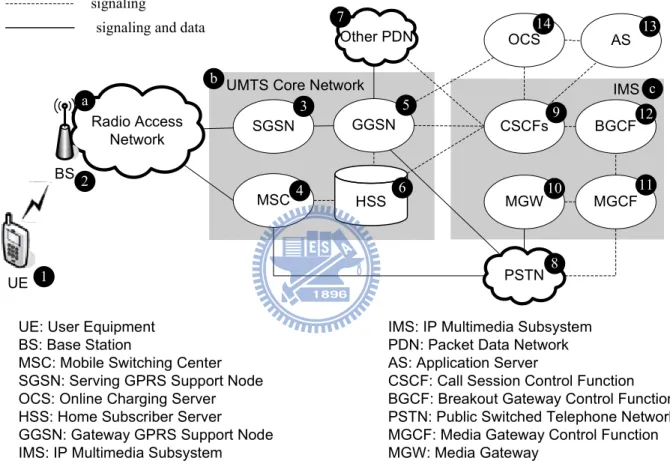
technology with the Internet [12, 13]. This section introduces the UMTS/IMS architecture. As illustrated in Figure 1.1, the UMTS/IMS network architecture consists of the radio access network (RAN; Figure 1.1 (a)), the UMTS core network (Fig 1.1 (b)), and the IMS network (Figure 1.1 (c)). In this figure, the dashed lines represent signaling links and the solid lines represent data and signaling links. The IMS signaling protocols allow the telecom operators to offer attractive services to their customers. Such protocols are like Session Initiation Protocol (SIP) [42, 29] for session signaling and Diameter protocol for Authentication, Authorization
UE Radio Access Network BS MSC GGSN OCS CSCFs Other PDN BGCF MGCF MGW AS PSTN IMS signaling and data
signaling
SGSN
UE: User Equipment BS: Base Station
MSC: Mobile Switching Center SGSN: Serving GPRS Support Node OCS: Online Charging Server HSS: Home Subscriber Server
GGSN: Gateway GPRS Support Node IMS: IP Multimedia Subsystem
IMS: IP Multimedia Subsystem PDN: Packet Data Network AS: Application Server
CSCF: Call Session Control Function BGCF: Breakout Gateway Control Function PSTN: Public Switched Telephone Network MGCF: Media Gateway Control Function MGW: Media Gateway a c 1 2 3 4 5 7 8 9 10 11 12 13 14 HSS 6
UMTS Core Network b
and Accounting (AAA).
In this architecture, a mobile user utilizes a User Equipment (UE; Figure 1.1 (1)) to com-municate with the network through the RAN, or more specifically, macro or femto Base Stations (BSs; Figure 1.1 (2)) [33]. In the core network, the Mobile Switching Center (MSC; Figure 1.1 (3)) handles all the circuit-switched operations (which is about Public Switched Telephone
Network (PSTN; Figure 1.1 (8))) while the Serving GPRS Support Node (SGSN; Figure 1.1
(4)) handles all the packet-switched operations and transfers all the data in the network. The SGSN connects the Gateway GPRS Support Node (GGSN; Figure 1.1 (5)) to access the external
Packet Data Network (PDN; Figure 1.1 (7)) or the IMS network. The Home Subscriber Server
(HSS; Figure 1.1 (6)) contains user-related subscription information, which can be utilized by core network nodes such as MSC, SGSN, GGSN, and IMS network.
In the IMS network, call and session control is implemented in the Call Session Control
Function (CSCF; Figure 1.1 (9)), which acts as a SIP server to facilitate SIP session setup and
teardown. The Media Gateway (MGW; Figure 1.1 (10)) transports the IMS user data traffic. The MGW provides user data transport between the UMTS core network and the PSTN (in-cluding media conversion bearer control and payload processing). The Media Gateway Control
Function (MGCF; Figure 1.1 (11)) controls the media resources in the MGW. The Breakout Gateway Control Function (BGCF; Figure 1.1 (12)) selects the network in which the PSTN (or
circuit switched domain) breakout is to occur. If the BGCF determines that a breakout is to occur in the same network, it selects an MGCF that is responsible for interworking with the PSTN. If the breakout occurs in another IMS network, the BGCF forwards the SIP request to another BGCF or an MGCF in the selected IMS network.
multi-Through standard protocols or languages (such as Java, SIP and XML), an application devel-oper can efficiently deploy mobile applications to launch new services and therefore reduce time-to-market. In Chapter 4, we will describe an application server with charging capability. The OCS (Figure 1.1 (14)) performs online charging and collects the billing information of the IMS with the CSCFs. Details of the charging functionalities are described in the next section.
1.2 Online Charging System
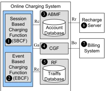
This section introduces the all-IP online charging system. In online charging, a service provider can charge its customers based on the price or the tariff of the requested service and the balance in the subscriber’s account in real time. Figure 1.2 illustrates the OCS architecture defined in 3GPP 32.296 [17]. The OCS supports two types of Online Charging Functions (OCFs), namely the Session-Based Charging Function (SBCF, Figure 1.2 (1)) and the Event-Based Charging
Function (EBCF, Figure 1.2 (2)).
The SBCF is responsible for network bearer and session-based services such as voice calls, GPRS sessions or IMS sessions. The SBCF triggers the session-based charging mode, and controls SIP sessions by appearing as a Back-to-Back User Agent (B2BUA) that sends messages to the initiating SIP user agents. It also performs charging on non-SIP based bearer systems (e.g, GPRS and other bearer channels) using the CAP or Ro reference point (depending on the communicating network node). The EBCF is responsible for event-based services. The EBCF triggers the event-based charging mode, and controls “one-shot” events such as short message delivery, and content downloading (e.g., for ring tones or games). The SBCF and EBCF have the ability to grant or deny the network resource usage.
bal-Online Charging System Recharge Server Billing System ABMF Account Database CGF RF Traiffs Database Session Based Charging Function (SBCF) Event Based Charging Function (EBCF)
AMBF: Account Balance Management Function; CGF: Charging Gateway Function; RF: Rating Function
Rc Ga Re Rr Bo 1 2 3 4 5 6 7
Figure 1.2: The Online Charging System Architecture
ances and other account data. When a user’s credit depletes, the ABMF connects the Recharge
Server (Figure 1.2 (6)) to trigger the recharge account function. The OCFs communicate with
the ABMF to query and update the user’s account. The charging data records (CDRs) generated by the charging functions are transferred to the Charging Gateway Function (CGF; Figure 1.2 (4)) in real time. The CGF acts as a gateway between the IMS/UMTS network and the billing system (Figure 1.2 (7)).
The Rating Function (RF; Figure 1.2 (5)) determines the price/tariff of the requested net-work resource (i.e, session, service or event) before and/or after service delivery. The deci-sion about when and how to perform charging for a service sesdeci-sion is handled by the charging policies provisioned in the RF. We note that in some cases, non-chargeable sessions (or sub-sessions) have to be explicitly monitored via “zero rating charging contexts” for consistency. The RF is responsible for providing a cost for the requested session, which can be charged by a wide variety of rateable instances such as volume, time and events. The OCF furnishes the
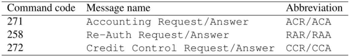
Table 1.1: Diameter Command Codes
Command code Message name Abbreviation
271 Accounting Request/Answer ACR/ACA
258 Re-Auth Request/Answer RAR/RAA
272 Credit Control Request/Answer CCR/CCA
necessary information (obtained from the IMS/UMTS network nodes) to the RF and receives the rating result (monetary or non-monetary credit units).
1.2.1 Diameter
The IMS uses the Diameter protocol to transfer the accounting information. The Diameter was derived from Remote Access Dial In User Service (RADIUS) protocol [41] to offer more flexibility, and is generally believed to be the next generation Authentication, Authorization, and
Accounting (AAA) protocol [24]. Diameter is an extensible protocol enabling AAA within and
across IP multimedia networks. The Diameter protocol has fail-over capabilities, and it runs over, for example, secure TCP/SCTP transport. Its modular architecture offers a flexible base protocol which allows application-specific extensions. The Diameter has proven successful in overcoming the limitations of RADIUS. Therefore, rapid growth in the usage of Diameter-based charging can be expected. The 3GPP has chosen the Diameter protocol to enable IMS network AAA capabilities [17, 2]
Like the RADIUS, the Diameter follows the client-server architecture where a client and a server interact through the Diameter request and answer message exchange. Several Diameter applications defined by Internet Engineering Task Force (IETF) are utilized in IMS, including the Diameter Credit Control (DCC) application for IP-based online charging control [30, 15].
is used for both Requests and Answers. Some examples of the command codes for Diameter charging messages are listed in Table 1.1. In this table, Accounting Request/Answer (ACR/ACA) commands support basic accounting, such as capacity planning, auditing, billing
and cost allocation. Re-Auth Request/Answer (RAR/RAA) commands initiate re-authentication service for a session; for example, in a prepaid service, the Diameter server that originally
au-thorized a session may need some confirmation that the user is still using the services. Credit Control Request/Answer (CCR/CCA) commands are responsible for the DCC mech-anism. The mechanism includes the process of checking whether credit is available, credit reservation, deduction of credit from the end user account when service is completed and re-funding of reserved credit that is not used. The message flow for DCC mechanism is explained in the following subsection.
1.2.2 The Diameter Message Flow
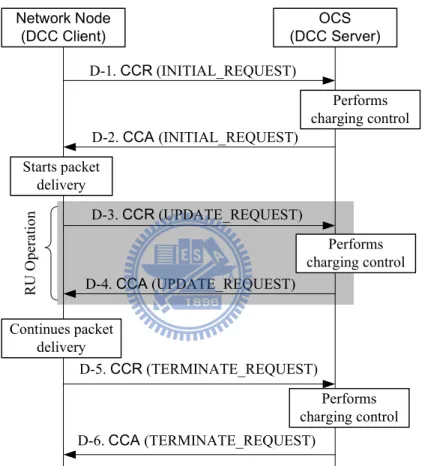
The Diameter message flow for session-based online charging includes three types of credit con-trol operations: INITIAL REQUEST (Steps D-1 and D-2 in Figure 1.3), UPDATE REQUEST (Steps D-3 and D-4 in Figure 1.3) and TERMINATE REQUEST (Steps D-5 and D-6 in Figure 1.3). The following operations are executed for session-based services.
Step D-1. To initiate the service session with the credit reservation, the network node (e.g., GGSN or CSCF) sends a CCR message with type “INITIAL REQUEST” to the OCS. This message indicates the amount of requested credit units.
Step D-2. Through the interactions among the SBCF, the ABMF and the RF, the OCS deter-mines the tariff of the requested service session and then reserves an equivalent amount of
Network Node (DCC Client) OCS (DCC Server) D-1. CCR (INITIAL_REQUEST) D-2. CCA (INITIAL_REQUEST) D-3. CCR (UPDATE_REQUEST) D-4. CCA (UPDATE_REQUEST) D-5. CCR (TERMINATE_REQUEST) D-6. CCA (TERMINATE_REQUEST) Starts packet delivery Performs charging control Performs charging control R U O p er at io n Performs charging control Continues packet delivery
edges the network node by sending a CCA message with type “INITIAL REQUEST” including credit reservation information. After receiving this message, the network node starts to deliver user packets for the session.
Step D-3. During the service session, the granted credit units may be depleted. If so, the net-work node sends a CCR message with type “UPDATE REQUEST” to the OCS to report the used credit units. The network node reports the amount of used credit, and requests for additional credit units. Packet delivery is suspended, and any newly arriving data packets are buffered at the network node.
Step D-4. When the OCS receives the CCR message, it debits the amount of consumed credit and reserves extra credit units for the service session. The OCS acknowledges the network node with a CCA message including the amount of credit units that have been reserved. After the receiving this message, the network node continues the packet delivery. Note that Steps D-3 and D-4 may repeat many times before the service session is complete. At Steps D-2 and D-4, if OCS cannot afford the requested amount of credit units, the session is forced to terminate. For the discussion purpose, Steps D-3 and D-4 are called a reserve
units (RU) operation.
Step D-5. When the session is completed, the network node sends a CCR message with type “TERMINATE REQUEST” to terminate the session and report the amount of used credit. Step D-6. The OCS deducts the amount of the used credit from the account. Then the OCS acknowledges the reception of the CCR message by sending a CCA message with type “TERMINATE REQUEST”. This message may contain the total cost information of the service.
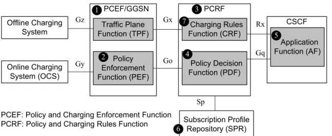
Offline Charging System Online Charging System (OCS) PCEF/GGSN Traffic Plane Function (TPF) Policy Enforcement Function (PEF) PCRF Charging Rules Function (CRF) Policy Decision Function (PDF) CSCF Application Function (AF) Subscription Profile Repository (SPR) Gz Gy Gx Go Rx Gq Sp 1 2 3 4 5 6 7
PCEF: Policy and Charging Enforcement Function PCRF: Policy and Charging Rules Function
Figure 1.4: PCC architecture for IMS service
1.3 Policy and Charging Control
In this session, we describe the Policy and Charging Control (PCC) architecture of the IMS. In 3GPP R5, the QoS control in IMS/GPRS is realized by the Session-Based Local Policy (SBLP) [10]. The SBLP utilizes the Policy Decision Function (PDF; see Figure 1.4 (4)) to make policy decisions based on session and media-related information obtained from the CSCF. In other words, the QoS policy is controlled by the PDF, where the policy rules can be formulated based on static information (such as the subscription profile), dynamic information, and the available resources. The combination of such policy rules, once met for a service request, can trigger a desired action (such as allowing the service with the requested bandwidth). This policy rule framework allows the telecom operators to deploy service logic while optimally utilizing the network resource. Specifically, by configuring the policy stored in the PDF, telecom operators are able to implement the QoS policy control flexibly for different applications in various IP networks.
between network nodes (e.g., GGSN and CSCF) and charging nodes (e.g., Charging Rules
Function (CRF; Figure 1.4 (7)) and PDF) [21]. The PCC architecture is shown in Figure
1.4. According to the classification of a subscriber, the type of the application to be accessed by the subscriber, and the local control QoS policy defined by the telecom operator, the IMS manages and controls the IP network resources (e.g., the allocated bandwidth) to the application and defines its priority. The Policy and Charging Rules Function (PCRF; Figure 1.4 (3)) is responsible for providing IMS charging rules and making policy decisions. In order to make decisions, the PCRF receives information from Application Function (AF; Figure 1.4 (5)) and the Subscription Profile Repository (SPR; Figure 1.4 (6)). The AF (a standalone application server or being implemented in the CSCF) provides the PCRF with information obtained from the session signaling over the Diameter Rx interface. The SPR provides the PCRF with QoS related information about the user’s subscription over the Sp interface.
The PCRF includes the PDF and the CRF. The QoS policy decisions made by the PDF are based on charging-related information (charging rules) and the service information provided from the CRF. In this way, the charging rules are consistent with the QoS policy. The QoS decisions are carried out by the Policy and Charging Enforcement Function (PCEF; Figure 1.4 (1)). The PCEF is a logical function implemented in a gateway (e.g., GGSN). This function includes the Traffic Plane Function (TPF) and the Policy Enforcement Function (PEF; Figure 1.4 (2)). The TPF provides bearer session information (e.g., the user identity, the negotiated QoS and the network-related information) to the CRF. The PEF is responsible for QoS control of the IP service flows. The PCRF communicates with the PCEF over the Diameter-based Gx interface for providing QoS information. Based on the QoS information, the PCEF sets up an aggregate for a service session (i.e., the requirements on the aspects of a connection, such as service response time, bandwidth limit, and so on). The PCEF uses the aggregate to control
downlink/uplink traffic for each bearer service session, i.e., for downlink scheduling and uplink policing.
The offline and online charging systems interact with PCEF for online credit control and the collection of offline charging information through Gz and Gy interfaces, respectively.
1.4 Organization of the Dissertation
Policy and charging are among the most important activities in telecommunications operation today. Based on the above discussion, we investigate the architecture and performance issues of policy and charging in the UMTS/IMS network. This dissertation contains four chapters in addition to this introductory chapter. Details for each chapter are described below.
Chapter 2 and 3 discuss charging issues in network level. In Chapter 2, we study the online credit reservation procedure for prepaid users in the UMTS OCS. If the assigned credit units are consumed before the session is completed, a reserve units operation is executed to obtain more credit units from the OCS. During the RU operation, packet delivery is suspended until extra credit units are granted from the OCS. To avoid session suspension during credit reservation, we propose the credit pre-reservation mechanism that reserves credit earlier before the credit at the GGSN is actually depleted. Analytic and simulation models are developed to investigate the performance of this credit pre-reservation mechanism. Our study provides guidelines to set up the parameters for our proposed mechanism.
In Chapter 3, we design and implement a testbed to investigate the PCC system in Long Term
Evolution (LTE). Specifically, we use the IMS call service as an example to demonstrate how to
implement an advanced mobile service with PCC in our testbed. The PCC system can handle the application level session information (e.g., information obtained from the Application Server)
and the network level bearer information (e.g., information obtained from the core network) dynamically. The corresponding performance measurement (e.g., the signaling delays) can be obtained through our testbed.
In Chapter 4, we focus on charging issues in application level. IMS provides an infrastruc-ture for service-oriented architecinfrastruc-ture (SOA) development through a service platform based on Parlay X, which is an open web service of telecommunication functionality. Through Parlay X API, application developers can create new services without knowing the details of the telecom-munication network (e.g., charging protocol). We design and implement the “group accounting system” service as an example to present how to use standard-based web service APIs to create a charging application in our platform.
Chapter 2
Credit Pre-reservation Mechanism for
UMTS Prepaid Service
The advanced mobile telecommunications operation incorporates data applications (specifi-cally, mobile Internet applications [50, 40]) with real-time control and management, which can be archived by the Online Charging System (OCS; Figure 1.1 (14)). Such convergence is essential to mitigate fraud and credit risks, and provide more personalized advice to users about charges and credit limit controls [45, 47, 46]. The OCS allows simultaneous prepaid and post-paid sessions to be charged in real-time [25]. Through online charging, the operator can ensure that credit limits are enforced and resources are authorized on a per-transaction basis.
The OCS assigns some prepaid credit units to the Diameter Credit Control (DCC) client (e.g., GGSN; Figure 1.1 (5)) for a user session. These credit units are decremented at the GGSN in real-time based on either the traffic volume or the duration time. After the assigned credit units are consumed, the GGSN may execute the reserve units (RU) operation to ask for more credit from the OCS.
OCS is depleted, the prepaid session is forced to terminate. During the RU operation, packet delivery is suspended until extra credit units are granted from the OCS. Delayed processing of user packets at the GGSN may seriously degrade the quality of service. To avoid suspension of packet delivery, this chapter proposes the credit pre-reservation mechanism (CPM) that reserves extra credit earlier before the credit units at the GGSN are actually depleted. Analysis and simulation experiments are conducted to investigate the performance of the mechanism. Our study indicates that the CPM can significantly improve the performance of the OCS prepaid mechanism.
2.1 Credit Pre-reservation Mechanism
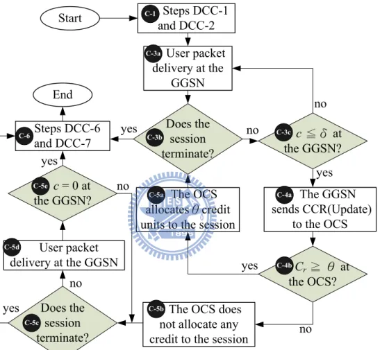
In the credit pre-reservation mechanism (CPM), we define a threshold δ. When the amount c of the remaining credit for the session is not larger than δ (i.e., c ≤ δ), the GGSN conducts an RU operation to request extra credit from the OCS. During the RU operation, the GGSN continues to process the user packets. Hopefully, the GGSN will receive the extra amount θ of credit units before c = 0, and therefore the user packets need not be buffered (i.e., they are not suspended for processing) at the GGSN. Figure 2.1 illustrates the flowchart of CPM, which modifies Steps D-3 to D-5 in Figure 1.3 as follows:
Step C-1. The session initiates by executing Steps D-1 and D-2 in Figure 1.3.
Step C-3a. The GGSN delivers the user packets and deducts the reserved credit units.
Step C-3b. If the processed packet is the last one of the service session, then Step C-6 is ex-ecuted to terminate the session (the session is successfully completed). Otherwise, the execution proceeds to Step C-3c.
Steps DCC-6 and DCC-7
The OCS does not allocate any credit to the session yes End Does the session terminate? c= 0 at the GGSN? yes yes no no The OCS allocatesθcredit units to the session User packet delivery at the GGSN Start User packet delivery at the GGSN Does the session terminate? c≦δ at the GGSN? no yes yes The GGSN sends CCR(Update) to the OCS Cr≧ θ at the OCS? no no Steps DCC-1 and DCC-2 C-6 C-3a C-3b C-3c C-4a C-4b C-5a C-5b C-5c C-5d C-5e C-1
Figure 2.1: Flowchart of the CPM (Steps C-1 and C-6 refer to Steps D-1, D-2, D-6 and D-7 in Figure 1.3
Step C-3c. Let δ be the CPM threshold. If c ≤ δ, Step C-4a is executed. Otherwise, the execution proceeds to Step C-3a.
Step C-4a. The GGSN sends a CCR message with type UPDATE REQUEST to request for additional credit. During the RU operation, if c > 0, the user packets are continuously delivered at the GGSN. When c = 0, the session is suspended and the newly arriving packets are buffered.
Step C-4b. If the OCS does not have enough credit units (i.e., Cr < θ), Step C-5b is executed. Otherwise, Step C-5a is executed.
Step C-5a. The OCS sends the CCA message to the GGSN to indicate that extra amount θ of credit units have been reserved for the session. Then the execution proceeds to Step C-3b. If the last packet arrives during the RU operation, the termination operation (Steps C-3b and C-6) is executed after the GGSN has received the CCA message. (This is called
delayed termination.) In this case, the session is successfully completed.
Step C-5b. The OCS sends the CCA message to the GGSN. This message indicates that no credit is reserved for the session.
Step C-5c. If the previously processed packet is the last one of the session, then the session is successfully completed. Step C-6 is executed.
Step C-5d. The GGSN continues to deliver the user packets.
Step C-5e. If c = 0, then the session is forced to terminate, and Step C-6 is executed. Other-wise, the execution proceeds to Step C-5c.
In the CPM, if δ is set too small, then the credit units for a session are likely to be depleted and the session must be suspended during the RU operation. On the other hand, if δ is set too large, many credit units are reserved in the active sessions, and the credit in the OCS is consumed fast. In this case, an incoming session has less chance to be served, and an in-progress session is likely to be force-terminated. Therefore, it is important to select an appropriate δ value to “optimize” the CPM performance.
2.2 Analytic Model for the CPM
In this section, we describe an analytic model to investigate the CPM performance. We assume that the prepaid session arrivals for a user form a Poisson process with rate γ. The inter-arrival time between two packet arrivals has the mean 1/λ. The round-trip transmission delay for the RU operation (i.e., the round-trip message delay for the CCR and CCA message pair) has the mean 1/µ. An arrival packet is the last one of the session with probability α; in other words, the session continues with probability 1 − α, and the expected number of packets delivered in a session is 1/α.
Initially, a user has C credit units at the prepaid account in the OCS. Without loss of gen-erality, we assume that each user packet consumes one credit unit. Define a low credit (LC)
period as an interval such that during this interval, c ≤ δ for a session. At the beginning of an
LC period, the session initiates an RU operation. If more than θ packets arrive during this RU operation, then θ − δ packets will be buffered at the GGSN. Consequently, at the end of the RU operation, another RU operation must be issued to obtain more credit units to absorb the buffered packets and to ensure that c > δ after the buffer is empty. Before an LC period ends, the RU operation may be executed for several times until the session has reserved more than δ
credit units. The output measures investigated in our study are listed below.
B: the average number of packets buffered during an RU operation W : the average packet waiting time
Pr: the probability that during an LC period, two or more RU operations are executed
Pnc: the probability that a session is not completely served; i.e., the probability that a new session request is blocked or an in-progress session is forced to terminate
Xs: the average number of the RU operations performed in a session
To derive Prand B, we first consider the case where α = 0; i.e., a session is never terminated. Let K be the number of packets arriving in one RU operation (excluding the first packet arrival that triggers the RU operation). It is clear that
Pr = Pr[K ≥ θ] (2.1)
We assume that an RU operation delay has the Erlang density function f (t) with the shape parameter b = 2 and the scale parameter h = 1/µ. (I.e., t is the summation of two Exponential delays. This assumption will be relaxed, and more general distributions will be considered in the simulation model) Therefore the Laplace-Stieltjes Transform f∗(s) of the RU operation delay is f∗(s) = µ µ µ + s ¶2 (2.2)
For α = 0, the probability that K = k can be calculated as follows: Pr[K = k, α = 0] = Z ∞ t=0 " (λt)k k! # e−λtf (t)dt (2.3) = µ λk k! ¶ Z ∞ t=0 tke−λtf (t)dt (2.4) = µ λk k! ¶ (−1)k · dkf∗(s) dsk ¸¯¯ ¯ ¯ s=λ (2.5) = µ λk k! ¶ (−1)k " dk dsk µ µ µ + s ¶2#¯¯ ¯ ¯ ¯ s=λ (2.6) = λ k(k + 1)µ2 (λ + µ)k+2 (2.7)
In (2.3), the RU operation delay is t with the probability f (t)dt. During period t, there are
k packet arrivals following the Poisson distribution with the rate λ. Equation (2.5) is derived
from (2.4) using Rule P.1.1.9 in [49]. Substitute (2.2) in (2.5), we obtain (2.6).
Now we consider the case when α > 0. If a session is terminated during an RU operation, Pr[K = k] is derived by considering the following cases:
(I) When k = 0, we have Pr[K = 0] = Pr[K = 0, α = 0] (II) When k > 0, there are two subcases:
(IIa) There are exactly k packet arrivals during an RU operation (with probability Pr[K =
k, α = 0]) and the session is not terminated by any of the first k −1 packets (with the
probability (1 − α)k−1). Note that the k-th packet can be the last one of the session. (IIb) There are more than k packet arrivals during an RU operation if the session is never terminated (with probabilityP∞i=k+1Pr[K = i, α = 0]), and the session is actually terminated at the k-th packet arrival (with probability (1 − α)k−1α).
Based on the above cases, Pr[K = k] is derived as Pr[K = k] = Pr[K = 0, α = 0] , k = 0 (2.8) Pr[K = k, α = 0] (1 − α)k−1 + ∞ X i=k+1 Pr[K = i, α = 0] (1 − α)k−1α , k > 0 (2.9)
From (2.7), (2.8) can be derived as
Pr[K = 0] = µ µ λ + µ ¶2 (2.10) For k > 0, Equation (2.9) is simplified as
Pr[K = k] = " λk(k + 1)µ2 (λ + µ)k+2 # (1 − α)k−1 + ∞ X i=k+1 · λi(i + 1)µ2 (λ + µ)i+2 ¸ (1 − α)k−1α = " (1 − α)k−1λk (λ + µ)k+2 # © (k + 1)µ2+ αλ [(k + 2)µ + λ]ª (2.11)
When θ > 0, from (2.1) and (2.11), Pris derived as
Pr = Pr[K ≥ θ] = ∞ X k=θ " (1 − α)k−1λk (λ + µ)k+2 # © (k + 1)µ2+ αλ [(k + 2)µ + λ]ª = " λθ(1 − α)θ−1 (λ + µ)θ+1 # [µ(θ + 1) + λ] (2.12) When θ = 0, P = Pr[K ≥ 0] = µ µ ¶2 + ∞ X Pr[K ≥ k] = 1 (2.13)
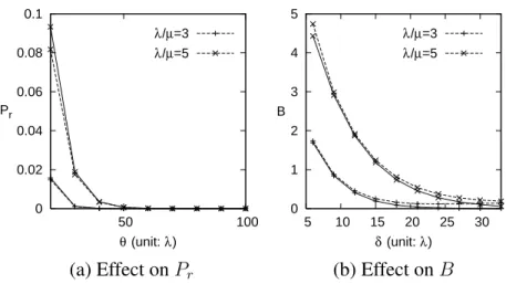
0 0.02 0.04 0.06 0.08 0.1 50 100 θ (unit: λ) Pr λ/µ=3 λ/µ=5 0 1 2 3 4 5 5 10 15 20 25 30 δ (unit: λ) B λ/µ=3 λ/µ=5
(a) Effect on Pr (b) Effect on B
Figure 2.2: Validation of simulation and analytic results on Pr and B (α = 0.01, γ/µ = 1/20, and δ = 0.3θ; Solid curves: analytic results; dashed curves: simulation results)
The expected number B of buffered packets is derived as follows: When the number k (of packet arrivals during an RU operation) is no less than the threshold δ (i.e., k ≥ δ), the session will have k − δ buffered packets. Therefore, from (2.11)
B = ∞ X k=δ (k − δ) Pr[K = k] = ∞ X k=δ (k − δ) " (1 − α)k−1λk (λ + µ)k+2 # © (k + 1)µ2+ αλ [(k + 2)µ + λ]ª = · (1 − α) λ λ + µ ¸δ+1 · δµ2+ αδλµ + 2µ2 + 2λµ + αλµ + αλ2 (1 − α) (µ + αλ)2 ¸ (2.14) The purpose of the analytic model is twofold: First, it partially verifies that the simulation model is correct. Second, it sheds light on the effects of the input parameters on Pr and B. Our simulation model is based on an event-driven approach widely adopted in mobile network studies, and the details are elaborated in Appendix A.
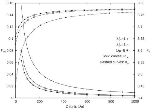
0 0.02 0.04 0.06 0.08 0.1 0.12 0.14 0.16 0 200 400 600 800 1000 3.4 3.45 3.5 3.55 3.6 3.65 3.7 3.75 3.8 C (unit: 1/α) Pnc Xs λ/µ=1 + λ/µ=3 × λ/µ=5 ✳ Solid curves: Pnc Dashed curves: Xs
Figure 2.3: Effects of λ/µ and C on Pnc and Xs (α=0.01,γ/µ=1/20, δ=0.3θ, and θ=50λ)
Figure 2.2. In this figure, the dashed curves represent the simulation results, and the solid curves represent the analytic results. These curves indicate that the analytic and the simulation results are consistent.
2.3 Numerical Examples
This section uses numerical examples to investigate the performance of the CPM. For the pre-sentation purpose, we assume that the packet termination probability is α = 0.01 and the session arrival rate (normalized by the message delivery rate) is γ = µ/20. For other α and γ/µ values, we observed similar results, which are not presented in this chapter. In Figures 2.2 and 2.3, the packet arrivals in a session have a Poisson distribution and the RU operation delay has an Erlang distribution. These Expontial-like assumptions are relaxed in Figures 2.4 and 2.5 by
considering the Pareto and the Gamma distributions. The effects of the input parameters λ/µ,
C, θ and δ are described as follows.
Effects on Pr. Figure 2.2 (a) shows how Pr is affected by θ and λ/µ. From (2.12) and (2.13), we have
lim
θ→0Pr = 1 and θ→∞lim Pr = 0 (2.15)
Therefore, it is obvious that Pr is a decreasing function of θ. When λ/µ is very small or vary large, we have
lim
λ/µ→0Pr= (1 − α)
θ−1 and lim
λ/µ→∞Pr = 0 (2.16)
When λ/µ increases, more packets arrive during an RU operation. When more than
θ+δ packets arrive during one RU operation, an extra RU operation will be immediately
executed. Consequently, Princreases. Therefore Pris an increasing function of λ/µ. Effects of λ/µ. Figure 2.2 (b) shows that B is increasing functions of λ/µ. From (2.14), we
have
lim
λ/µ→0B = 0 and λ/µ→∞lim B =
(1 − α)δ
α (2.17)
When λ/µ increases, it is likely that more than δ packets will arrive during the interval of the RU operation. Note that W correlates positively with B. Therefore both B and W increase as λ/µ increases.
When λ/µ → ∞, we found that the B value in (2.17) is higher than the simulation result (not shown in this Figure), which is explained as follows: When λ/µ → ∞, all packets for a session will arrive before the end of the first RU operation, and therefore the B value in (2.17) is determined by α. In simulation, the session is always in the “low-credit” status
(in the LC period), and every time an RU operation is performed, the number of buffered packets at the end of the operation is reduced. Therefore the expected value B is smaller than that shown in (2.17). To avoid buffer overflow, the B value in (2.17) should be considered in the system setup.
Figure 2.3 shows that Pnc increases as λ/µ decreases. Since α is fixed, when λ/µ
de-creases, the session holding times become longer, and it is likely that more new sessions will arrive during the holding time of an existing session. Therefore, when λ/µ decreases, more sessions will exist at the same time. Suppose that the credit in the OCS suffices to support these sessions if they are sequentially delivered. It is clearly that the OCS may not be able to support these sessions if they are delivered simultaneously. In this case, a newly incoming session is rejected because the credit in the OCS is depleted (while there are unused credit units held in the multiple in-progress sessions). Therefore, Pnc increases as λ/µ decreases.
In Figure 2.3, Xs is a decreasing function of Pnc because the number of RU operations performed in a force-terminated session is less than that in a complete session. Therefore,
Xsincreases as λ/µ increases.
Effects of C. Figure 2.3 shows that the output measures (Pncand Xs) are only affected by the “end effect” of C. As C increases, it is more likely that the remaining credit units in the OCS suffice to support one RU operation and such end effect becomes insignificant. Similar to the λ/µ impact, Pnc is a decreasing function of C, and Xs is an increasing function of C. Figure 2.3 indicates that when C is sufficiently large (e.g. C ≥ 600/α), the end effect of C can be ignored. Same phenomenon is observed for B and W , and the results are not shown.
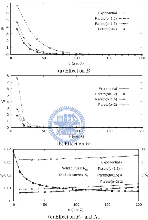
0 1 2 3 4 5 6 7 0 50 100 150 200 θ (unit: λ) B Exponential Pareto(b=1.2) Pareto(b=1.5) Pareto(b=2) (a) Effect on B 0 1 2 3 4 5 6 7 8 0 50 100 150 200 θ (unit: λ) W Exponential Pareto(b=1.2) Pareto(b=1.5) Pareto(b=2) (b) Effect on W 0 0.01 0.02 0.03 0.04 0 50 100 150 200 0 3 6 9 12 θ (unit: λ) Pnc Xs Exponential + Pareto(b=1.2) × Pareto(b=1.5) ✳ Pareto(b=2) ❏ Solid curves: Pnc Dashed curves: Xs (c) Effect on Pncand Xs
Figure 2.4: Effects of θ and the packet interarrival time distribution (α=0.01, γ/µ=1/20, δ=0.3θ,
Since δ = 0.3θ in Figure 2.4 (b), from (2.13) and (2.14), we have lim θ→∞B = limδ→∞B = 0 and lim θ→0B = limδ→0B = λ (2µ + αλ) (1 − α) (µ + αλ)2 (2.18)
The non-trivial result is that there is a threshold θ value (θ ≈ 100λ in Figure 2.4) such that beyond this threshold value, increasing θ does not improve the performance. On the other hand, Figure 2.4 (c) shows that Pnc linearly increases as θ increases. When θ increases, more credit units are reserved in an RU operation, and the credit in the OCS is consumed fast. Therefore, a newly incoming session has less chance to be served, and an in-progress session is likely to be force-terminated.
Effects of packet interarrival time distribution. Figure 2.4 considers the packet arrival times with the Exponential and the Pareto distributions with mean 1/λ. In the Pareto distribu-tion, the shape parameter b describes the “heaviness” of the tail of the distribution. It has been shown that the Pareto distribution with 1 ≤ b ≤ 2 can approximate the packet traffic very well [26, 51].
Figure 2.4 shows that B, W and Pnc are decreasing functions of b. When b decreases,
the tail of the distribution becomes longer, and more long packet interarrival times are observed. Since the mean value 1/λ is fixed for the Pareto distribution in Figure 2.4, more long packet interarrival times also imply more short packet interarrival times. The number of short interarrival times must be larger than that of long interarrival times because the minimum of the interarrival time is fixed but the maximum of the interarrival time is infinite. Thus, it is likely that more packets will arrive during an RU operation, and B and
to arrive, and are rejected by the OCS, which contributes to Pnc. Therefore Pnc increases as b decreases.
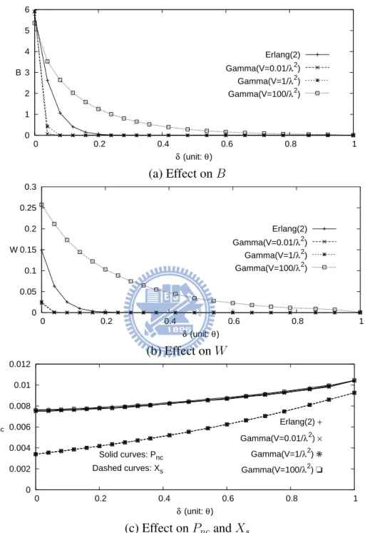
Effects of δ. Similar to the effect of θ, Figure 2.5 shows that B and W are decreasing functions of δ (see (2.18)), and Pnc is a linearly increasing function of δ. A non-trivial observation is that when δ ≥ 0.6θ, B and W approach to zero. It implies that selecting δ value larger than 0.6θ will not improve the performance. Figure 2.5 (c) shows that Xsis an increasing function of δ. When the amount of the credit in a session is less than δ, a CCR message is sent to the OCS. Therefore, for a fixed θ, when δ is increased, Xsincreases.
Effects of RU operation delay distribution. Figure 2.5 considers the Erlang with b = 2 (which
is a Gamma distribution with variance V = 18/λ2) and Gamma distributed RU operation
delays with variances V = 0.01/λ2, 1/λ2, and 100/λ2, respectively.
The figure indicates that Pnc and Xs are not significantly affected by the RU operation delay distribution. On the other hand, B and W increase as V increases. As V increases, more long and short RU operation delays are observed. In long RU operation delays, it is likely that more than δ packets arrive. Therefore the packets are more likely to be buffered and delayed processed.
2.4 Conclusion
In this chapter, we investigated the prepaid services for the UMTS network where multiple prepaid and postpaid sessions are simultaneously supported for a user. We described the pre-paid network architecture based on UMTS, and proposed the credit pre-reservation mechanism (CPM) that reserves extra credit earlier before the credit at the GGSN is actually depleted.
0 1 2 3 4 5 6 0 0.2 0.4 0.6 0.8 1 δ (unit: θ) B Erlang(2) Gamma(V=0.01/λ2) Gamma(V=1/λ2) Gamma(V=100/λ2) (a) Effect on B 0 0.05 0.1 0.15 0.2 0.25 0.3 0 0.2 0.4 0.6 0.8 1 δ (unit: θ) W Erlang(2) Gamma(V=0.01/λ2) Gamma(V=1/λ2) Gamma(V=100/λ2) (b) Effect on W 0 0.002 0.004 0.006 0.008 0.01 0.012 0 0.2 0.4 0.6 0.8 1 δ (unit: θ) Pnc Erlang(2) + Xs Gamma(V=0.01/λ2) × Gamma(V=1/λ2) ✳ Gamma(V=100/λ2) ❏ Solid curves: Pnc Dashed curves: Xs (c) Effect on Pncand Xs
Figure 2.5: Effects of δ and the RU operation delay distribution (α=0.01, γ/µ=1/20, θ=100λ,
C = 600/α, λ/µ=3, and the packet arrival times have the Pareto distribution with the mean 1/λ
during a reserve units (RU) operation and the probability Prthat more than one RU operation is executed during a low credit (LC) period. Simulation experiments are conducted to investigate the performance of CPM. We have the following observations:
• B and W increase as λ/µ increases. The probability Pncthat a session is not completely
served decreases as λ/µ increases. The average number Xs of RU operations performed
in a session is an increasing function of λ/µ.
• B, W, Xsand Pnc are only affected by the end effect of C. When C is sufficiently large (e.g., C ≥ 600/α, where α is the probability that an arrival packet is the last one of the session), the end effect can be ignored.
• B, W and Xsdecrease but Pncincreases as θ increases. There is a threshold θ value (e.g.,
θ ≈ 100λ) such that beyond this threshold value, increasing θ does not improve the CPM
performance.
• B and W decrease but Xsincreases as δ increases. When δ is large (e.g., δ ≥ 0.6θ), both
B and W approach zero.
• Pr increases when λ/µ increases or θ decreases.
• B, W and Pncincrease as the tail of the packet arrival time distribution becomes longer.
• B and W increase as the variance of the RU operation delay increases.
Our study provides guidelines to select the CPM parameters. Specifically, it is appropriate to select C ≥ 600/α, θ ≈ 100λ, and δ ≈ 0.6θ.
Chapter 3
Policy and Charging Control System for
Advanced Mobile Services
The 3rd Generation Partnership Project (3GPP) Release 8 introduces Long Term Evolution (LTE) that is a set of enhancements to the Universal Mobile Telecommunications System (UMTS). Since LTE offers higher throughput and lower latency, Policy and Charging Control (PCC) has become a major issue for guaranteed security, Quality of Service (QoS) and flexible charging. We design and implement a testbed to investigate the impact of PCC on advanced mobile service deployment. This experimental testbed provides web-based user interface for an administrator (e.g., the telecom operator or a subscriber) to conveniently set up the service admission policy (e.g., for online charging budget). These policy settings are converted to PCC rules and are used to ensure the QoS.
MME Radio Access Network PDNGW Sp PDN SPR UE 3
PDN: Packet Data Network PDNGW: PDN Gateway
SPR: Subscription Profile Repository UE: User Equipment
PCRF: Policy and Charging Rules Function PCEF: Policy and Charging Enforcement Function
7 5
4
Gx Gy
signaling and data signaling
S5
9 LTE Core Network
eNB 10 HSS 11 UMTS Network S11 S3 S6a S12
MME: Mobility Management Entity SGW: Serving Gateway
HSS: Home Subscriber Server SGSN: Serving GPRS Support Node eNB: e Node B
OCS: Online Charging Server OCS 6 SGW 8 PCRF 1 PCEF 2 UMTS Radio Access Network SGSN 4
3.1 Policy and Charging Control Architecture in LTE
Net-work
As illustrated in Figure 3.1, the LTE core network (also known as Evolved Packet Core (EPC)) includes the Mobility Management Entity (MME; Figure 3.1 (10)), the Serving Gateway (SGW; Figure 3.1 (8)) and the Packet Data Network Gateway (PDNGW; Figure 3.1 (2)). The MME manages service sessions authentication (by interacting with the Home Subscriber Server; HSS, Figure 3.1 (11) or Figure 1.1 (6)), paging, roaming and bearer management. The MME also provides mobility management between LTE and UMTS networks (i.e., it connects to the
Serv-ing GPRS Support Node (SGSN); Figure 3.1 (4) and Figure 1.1 (4)) with the S3 interface. The
SGW plays a role similar to the SGSN in UMTS, which routes and forwards user data packets between the gateway node (PDNGW or Gateway GPRS Support Node (GGSN)) and the radio access network. The PDNGW provides connectivity from the User Equipment (UE; Figure 3.1 (3)) to packet data network (PDN; Figure 3.1 (7) or Figure 1.1 (7)). The PDNGW is similar to GGSN (Figure 1.1 (5)) in UMTS.
When a UE initiates a service session, the session is connected to the PDNGW through the radio access network (Figure 3.1 (5)) and the SGW [19]. Before establishing the connection, the PDNGW requests the PCC rules of the UE from the Policy and Charging Rules Function (PCRF; Figure 3.1 (1)). The PCRF specifies the PCC rules for a service session so that policy enforcement and charging management can be performed in the LTE network. The Policy
and Charging Enforcement Function (PCEF; Figure 3.1 (9)) is implemented at the PDNGW.
According to the subscriber’s charging plan, the network service to be accessed by the UE and the control policy defined by the telecom operator, the PCRF makes policy decisions and provides the PCC rules to the PCEF through the Gx interface (see Chapter 9 in [36]). The
LTE Core Network IP Access Network Admin / IP Network UE
CSCF: Call Session Control Function PCC: Policy and Charging Rules Control PCRF: Policy and Charging Rules Function SPR: Subscription Profile Repository PDN: Packet Data Network
OCS: Online Charging System SQL: Structured Query Language SGW: Serving Gateway Mobile UE Radio Access Network Diameter Module Policy Enforcement Module PDNGW/PCEF IP Filter Handler Managed IP Network PCRF Diameter Module PCC Rules Handler SQL Module SGW Web Server OCS SPR4 CSCF SIP Gy Gx Gxx SIP SIP SQL
SIP Signaling and data PCC Signaling
SIP
IMS(Simplified)
Figure 3.2: The Block Diagram for the PCC Testbed Implementation
Gx interface as well as Gg and Gxx [5, 7] are implemented by the Diameter protocol [24, 30] for Authentication, Authorization and Accounting (AAA). This testbed allows operators to experiment on advanced mobile services with PCC control without implementing these services in the commercial telecom system. This chapter is organized as follows: we first present the PCC testbed and its detailed design, and we use an IMS call control service as an example to show how our PCC testbed works. Finally, we provide measurement results to investigate the performance of the PCC testbed.
3.2 The PCC Testbed
This section describes a PCC testbed for advanced mobile services. We first describe the func-tional blocks of PCC, and use the IMS call control service as an example to illustrate the PCC
capabilities. In Figure 3.2, the dashed lines represent PCC signaling (e.g., Diameter and SQL messages) and the solid lines represent the SIP signaling and data. The UEs can reside in the IP access network (i.e., Figure 3.2 (9)) or the mobile network (e.g., Radio Access Network; Figure 3.2 (11)). The IP network UE connects to the IMS network (Figure 3.2 (c)) through managed IP network (QoS guaranteed private Internet; Figure 3.2 (10)). In our testbed, the administrator (e.g., the telecom operator or a subscriber) configures the PCC settings through a web-based portal (i.e., the Web Server; Figure 3.2 (7)) offered by the operator. The PCC settings are con-verted to PCC rules for access control in our testbed. The access control is handled based on the call duration time limit (e.g., a subscriber is only allowed to use the cell phone for 30 minutes per day) and the bandwidth limit. Through appropriate PCC settings, the PCC services (e.g., the IMS call service) can be easily deployed.
3.2.1 The Functional Blocks of the PCC Testbed
The functional modules of PCRF (Figure 3.2 (1) or Figure 1.4 (1)) and PCEF (Figure 3.2 (3) or Figure 1.4 (2)) in our testbed can be found in Figure 3.2. The PCRF includes the Diam-eter Module (Figure 3.2 (a)), the PCC Rules Handler (Figure 3.2 (b)) and the SQL Module (Figure 3.2 (c)). The PCRF Diameter Module implements the Gx and Rx interfaces [8]. This module communicates with the IMS Call Session Control Function (CSCF) (Figure 3.2 (2)) for delivering the service request over the Diameter Rx Authorize Authenticate Request/Answer (AAR/AAA) messages. The Diameter Module also communicates with the PDNGW (Figure 3.2 (3) or Figure 1.4 (9)) to provide the PCC rules through the Diameter Gx Credit Control Request/Answer (CCR/CCA) messages. This module can be reused in the PCEF for the Diameter messages exchange. A Diameter message includes infor-mation of the service session, such as the caller ID, serving time, and the callee ID. The PCC
Rules Handler collects the service requests from the CSCF and retrieves the subscriber infor-mation in the service request. Then the PCRF uses the subscriber inforinfor-mation (e.g., the caller ID) to query the SPR (Figure 3.2 (4)) for retrieving the PCC information of the caller and callee through the SQL Module. The SQL Module queries the SPR to retrieve the subscriber profile by SQL commands. Based on the query results and the subscriber information, the PCC Rules Handler makes the PCC rules for the service session, and sends the rules to PCEF/PDNGW for PCC rule enforcement.
The PCEF is located in PDNGW, which consists of three PCC modules: the Policy Enforce-ment Module (Figure 3.2 (d)), the Diameter Module (Figure 3.2 (f)) and the IP Filter Handler (Figure 3.2 (e)). The Policy Enforcement Module executes the PCC rules and controls the packet transmission by invoking the IP Filter Handler, e.g., the service session will be forced to terminate if the call duration time limit is reached. When the Policy Enforcement Module decides to terminate a service session, it will send a Session Initiation Protocol (SIP) BYE mes-sage [42] to the UE. The PCEF Diameter Module implements the Gx and Gy interfaces. The Diameter Module retrieves the PCC rules from the PCRF through Gx and communicates with the Online Charging Server (OCS; Figure 3.2 (8) or Figure 1.4 (6)) through Gy. The IP Filter Handler enforces the rules by the iptables [48], which is included in the Linux kernel. The iptables monitors the incoming and outgoing network packets. By default, the IP Filter Handler blocks every packet. When it receives the PCC rules from the PCRF, the iptables setting will be modified to allow the packet transmission for controlling the session duration or the bandwidth. When the session is terminated, the bandwidth setting will be removed and the iptables restores to its previous setting. In our implementation, we use the following two iptables settings to filter packets.
(1) public void CallDurationControlRule() {
(2) Runtime.getRuntime().exec(“iptables -N FORWARD -s ” +
subscriberIP + “ -j ACCEPT”);
(3) Timer timer = new Timer();
(4) timer.schedule(new Task(), duration*1000);
...
}
class Task extends TimerTask { public void run(){
(5) Runtime.getRuntime().exec(“iptables -N FORWARD -s ” +
subscriberIP + “ -j DENY”);
(6) // terminate the call service session
} }
Figure 3.3: Call Duration Control Program Segment
by default. When the PDNGW receives the PCC rules, the iptables setting function Call-DurationControlRule shown in Figure 3.3 will be executed. Line 2 allows all the packets from the subscriber. In the meanwhile, we set a timer to control the call duration (Lines 3 and 4). If the call duration time limit is reached, the previous iptables setting will be removed (Line 5) and the service session will be forced to terminate (Line 6).
(1) public void BandwidthControlRule() {
(2) Runtime.getRuntime().exec(“iptables -N chain” + chainNo);
(3) Runtime.getRuntime().exec(“iptables -A FORWARD -s ” +
subscriberIP + “ -j chain” + chainNo);
(4) Runtime.getRuntime().exec(“iptables -A chain” + chainNo + “ -s ” +
subscriberIP + “-m limit –limit 10/s –limit-burst 5 -j ACCEPT”);
}