國 立 交 通 大 學
電子工程學系 電子研究所碩士班
碩
士
論
文
針對最佳近似後佈局階段雙通孔設計之最小花費與最大流量之
演算法
Near-Optimal Post-Layout Double-Cut Via Insertion by Efficient
Minimum Cost Maximum Flow Algorithm
研 究 生:魏綸君
指導教授:陳宏明 博士
針對最佳近似後佈局階段雙通孔設計之最小花費與最
大流量之演算法
Near-Optimal Post-Layout Double-Cut Via Insertion by
Efficient Minimum Cost Maximum Flow Algorithm
研究生: 魏綸君
Student: Lun-Chun Wei
指導教授: 陳宏明 博士 Advisor: Prof. Hung-Ming Chen
國 立 交 通 大 學
電子工程學系 電子研究所碩士班
碩士論文
A Thesis
Submitted to Department of Electronics Engineering & Institute of Electronics College of Electrical and Computer Engineering
National Chiao Tung University in Partial Fulfillment of Requirements
for the Degree of Master
in
Electronics Engineering October 2007
Hsinchu, Taiwan, Republic of China
針對最佳近似後佈局階段雙通孔設計之最小花費與最大流量之演算法
研究生:魏綸君 指導教授:陳宏明 博士
國立交通大學
電子工程學系 電子研究所碩士班
摘要
隨著積體電路設計的複雜度一直在增加,因為導通孔的故障而損失的良率也是越 來越嚴重。比較被大家知道也被高度推薦的方法是在每個導通孔旁邊加入冗餘導通孔 以減少因為導通孔的故障而損失的良率。雙導通孔插入一般都是在後佈局階段執行。 在此論文中,我們提出了一個建立圖表的演算法來處理冗餘導通孔插入,以達到較高 的雙導通孔插入率。首先利用所提出的建立圖表演算法從已知的佈局建立一個有方向 性的圖表以同時考慮所有的導通孔。接著從這個有方向性的圖表中,利用最小花費與 最大流量這個方法去找出最多的雙導通孔。另外,我們提出了一個可以在工程修改命 令之後有效率地更新雙導通孔插入的方法。根據實驗結果可以得知我們所提出的方法 都能產生不錯的結果。 iNear-Optimal Post-Layout Double-Cut Via Insertion by Efficient
Minimum Cost Maximum Flow Algorithm
Student: Lun-Chun Wei Advisor: Prof. Hung-Ming Chen
Department of Electronics Engineering
& Institute of Electronics
National Chiao Tung University
Abstract
As the integrated circuits design complexity is continuously increasing, the yield loss due to via failure becomes more significant. Adding a redundant via adjacent to each single via is a well known and highly recommended method to reduce yield loss due to via failure. Generally, redundant via insertion is performed at the post-layout stage. In this thesis, we propose a graph construction algorithm for the redundant via insertion problem to reach a higher insertion rate for improving the manufacturing yield. First we construct a directed conflict graph from the given routing result to consider all the vias of a design simultaneously. Then we use minimum cost maximum flow to find the maximum number of double-vias from the directed conflict graph. In addition, due to design ECO, we present an algorithm to update the solution very efficiently. The experimental results show our algorithms perform well.
誌謝
首先要特別感謝的人,是我的指導教授陳宏明老師,沒有老師的指導與包 容,學生是不可能有能力完成這篇論文的。 此外,要感謝的是 VDA LAB 實驗室所有的成員,謝謝他們兩年來的砥勵、 幫助及帶給我的歡樂,讓我兩年的生活充滿歡笑及淚水。 另外,在研究的過程中,要感謝清華大學王廷基教授及其團隊所提供的協 助,讓我能順利完成這篇論文。 家人對我的支持、鼓勵更是我研究路上最大的依靠,對他們的感謝,更是筆 墨難以形容。 最後由衷感謝所有我幫助關懷過我的人。 魏綸君 民國九十六年十月 於新竹 vContents
1 Introduction 1
1.1 Our Contributions . . . 4
1.2 Organization of the Thesis . . . 4
2 Preliminaries 5 2.1 Double-Cut Vias . . . 5
2.2 Previous Works . . . 6
2.2.1 Redundant Via Insertion During Routing Stage . . . 6
2.2.2 Redundant Via Insertion During Post-Routing Stage . . . 6
2.3 Problem Formulation . . . 8
3 Methodology 9 3.1 Directed Conflict Graph . . . 9
3.2 Minimum Cost Maximum Flow (MCMF) . . . 12
3.2.1 Maximum Flow . . . 14
3.2.2 Minimum Cost Flow . . . 14
3.2.3 Solving the Problem . . . 15
4.1 An Incremental Algorithm for Updating the Solution . . . 20
5 Experimental Results 22
6 Conclusion 26
List of Figures
1.1 Single via structure. (a) Top view. (b) 3D view. . . 2
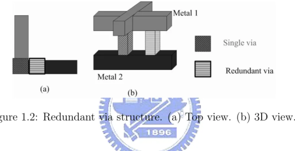
1.2 Redundant via structure. (a) Top view. (b) 3D view. . . 2
1.3 Illustration of redundant via insertion. . . 3
2.1 Illustration of double-cut via types [8]. . . 6
2.2 An example of conflict graph construction [8]. (a)Routing layout. (b)Resulting conflict graph. . . 8
3.1 An example of conflict condition. (a)Layout solution. (b)Simple di-rected conflict graph. . . 11
3.2 Construction of directed conflict graph. (a)Routing layout. (b)Resulting directed conflict graph. . . 13
3.3 Another example of construction of directed conflict graph. (a)Routing layout. (b)Resulting directed conflict graph. . . 17
3.4 Two solutions from problem 3.1 of Figure 3.3. (a)Conflict solution because r1 conflicts with r3. (b)Best solution. . . 18
4.1 Overview of the incremental algorithm for update the redundant via insertion porblem. . . 21
List of Tables
5.1 The information of five test cases [8]. . . 22
5.2 Statistics on conflict graphs. . . 23
5.3 Statistics on directed conflict graphs. . . 23
5.4 The experimental results on test cases: Comparison for post-routing redundant via insertion with H2K [8]. We insert more redundant vias than H2K on C4 circuit. . . 24
5.5 CPU time of our algorithm and H2K [8] from different platform. Our input file is the conflict graph from [8] and their input file is the layout solution. . . 25
5.6 The timing comparison between full process and incremental algo-rithm after ECO-design on C5 circuit. CPUF(s) represents the total runtime includes directed graph construction and MCMF after ECO-design to solve the redundant via insertion problem. CPUI(s) gives the runtime of incremental algorithm includes finding the affected set and MCMF to update the solution of the redundant via insertion after ECO-design. . . 25
Chapter 1
Introduction
With the advance of integrated circuits technologies, it becomes more and more difficult to maintain the manufacturability and high chip yield. Hence a new design methodology, design for manufacturability (DFM) methodology, has been suggested to improve chip yield and manufacturability of a design [12] [16] [2], among the important issues we studied the redundant via insertion problem.
In integrated circuits, vias are components to connect wire segments on different metal layers. Figure 1.1 shows the single via structure. As the design complexity is continuously increasing, the number of vias becomes larger and larger. However, vias may fail partially or completely due to various reasons such as electromigration, cut misalignment, random defects, and/or thermal stress induce voiding effects [11] [5] [10]. A complete failure will introduce a broken net, and a partial failure will increase the resistance of the contact and lead to timing problems. Therefore, it becomes more and more important to consider yield loss due to via failure and reduce it among DFM problems.
Adding a redundant via adjacent to each single via is a well known method to improve via yield and reliability. A single via together with redundant vias inserted next to it without violating any design rule is defined as a double via, and Figure 1.2 shows the top view and 3D structure of double via. If one single via fails, its
Figure 1.1: Single via structure. (a) Top view. (b) 3D view.
Figure 1.2: Redundant via structure. (a) Top view. (b) 3D view.
redundant one can still work to take the place of the failing one. Both vias failing simultaneously is less possible than a single via failure and [13] illustrates that double vias lead to 10X-100X smaller failure rate than single vias. Besides, after adding a redundant via, the whole via resistance is reduced.
Redundant via insertion has been greatly recommended by major foundries for their 90nm and 65 nm processes to improve the yield [1]. Many major EDA vendors such as Cadence and Synopsys have already combined the redundant via insertion with their latest routers. Among recent researches about redundant via insertion, the objective is to maximize the number of double vias. For example, Figure 1.3 (a) represents the original design. In Figure 1.3 (b), we can see that only two single vias can be replaced with double vias. But in Figure 1.3 (c), all the three single vias can be replaced with double vias, which is better because of higher redundant via insertion rate.
Figure 1.3: Illustration of redundant via insertion.
Therefore, the yield loss due to via failure becomes more important and the re-lated researches are all about redundant via insertion, but how to find the maximum number of redundant vias is a challenge. This thesis presents a method to find the maximum number(almost) of redundant vias to improve yield. Besides, if we have already found the maximum number of redundant vias as our solution from the given layout before some ECO changes, how to efficiently update the solution after ECO-design becomes the second goal of our thesis.
1.1
Our Contributions
In this thesis, we propose a graph construction algorithm to solve the redundant via insertion problem to reach a higher rate for improving the manufacturing yield. First we use our graph construction algorithm to construct the directed conflict graph from the given routing result to consider all the vias of a design simultaneously. Then we use minimum cost maximum flow to find the maximum number of redundant vias from the directed conflict graph. Experimental results show that our algorithm can get almost optimal solution for improving the redundant via insertion rate. In addition, after ECO for the whole design, we can efficiently update the solution by incremental algorithm. The experimental results show it is very efficient for updating the optimal solution.
1.2
Organization of the Thesis
The rest of this thesis is organized as follows. Chapter 2 gives the preliminaries of this thesis and problem formulation. Chapter 3 is our complete methodology to solve the redundant via insertion problem. Chapter 4 presents the incremental algorithm to update the optimal solution after ECO-design. Chapter 5 shows the experimental results, then we conclude this thesis in Chapter 6.
Chapter 2
Preliminaries
In this chapter, we will describe what double-cut vias mean, why we insert redundant via in the post-routing stage, and the problem formulation.
2.1
Double-Cut Vias
A single via together with redundant vias inserted next to it without violating any design rule is defined as a double via, and it is feasible if replacing the single via with the double via will not violate any design rule, assuming none of the other single vias has any redundant via inserted in the design; otherwise the double via is defined as an infeasible one.
A double-cut via means that a single via together with just only one redundant via inserted next to it, actually a single via can have at most four redundant vias inserted next to it if without violating any design rule. Therefore, according to the position of the redundant via, a double-cut via can be classified into four types as shown in Figure 2.1; a single via is illustrated in (a) and its position is defined at its center; (b), (c), (d), and (e) are the four types of double-cut vias, which are named DVU, DVR, DVD and DVL respectively. So if given a single via i, its double-cut via of type j (j∈ DVU, DVR, DVD, DVL)is denoted by dv(i,j).
Figure 2.1: Illustration of double-cut via types [8].
2.2
Previous Works
Several works have proposed different issues about redundant via insertion problem, such as [3], [9], [8], [7], [4], [14] and [15]. The given methods in these works are performed either during the routing stage or post-routing stage. The purposes of these methods are achieving higher redundant via insertion rate to improve reliability and yield.
2.2.1
Redundant Via Insertion During Routing Stage
[14] and [15] both consider redundant via insertion in the routing stage. During maze routing, [14] transforms the problem to a multiple constraint shortest path problem, and solves it by Lagrangian relaxation technique. But the high time complexity of Lagrangian relaxation limits the problem size. [15] presents an improved multi-level Full-chip routing system which integrates global routing and detailed routing algorithms to achieve great enhancement in yield and reliability considering the re-dundant via insertion. It minimizes the number of vias first and inserts rere-dundant vias later.
2.2.2
Redundant Via Insertion During Post-Routing Stage
However, considering redundant via insertion during routing stage may degrade routability and increase the number of vias. Besides, post-routing ECO operations
may change routing results and introduce extra vias into designs for the purpose of fixing timing and other problems. Therefore it is usually to perform redundant via insertion after the routing stage to improve the yield and reliability of vias.
[3] solves the redundant via insertion problem in the post-routing stage but does not provide further details. [9] considers the single vias individually to perform redundant via insertion and the solution is locally optimal. [4] formulates the re-dundant via insertion problem as a bipartite matching problem, which can solve the problem optimally when the design only involves at most three layers. [7] consid-ers redundant via insertion, line end extension and via density simultaneously, and presents a two-stage approach to solve the problem. [8] presents an efficient conflict graph construction algorithm, each node in the conflict graph represents the feasible via. Therefore, finding out the maximum number of nodes of the conflict graph also means that finding out the maximum number of single vias each of which can be replaced with a double-cut via. Hence a maximum independent set (MIS) of the conflict graph is a set having the maximum number of double-cut vias that can be inserted into the design. [8] also presents an MIS heuristic to solve the problem, but the time complexity is considerably high. The definition of the conflict graph is given as follows [8] :
Definition 2.1 (Conflict graph)
A conflict graph G(V,E) is a undirected graph constructed from a detail routing solution. For each single via v on a single net, if its redundant-via candidate is feasible, there exists a vertex Vi,j in V. An edge (V1,V2)∈ E if and only if V1 and V2
come from the same single via, or they conflict with the other when they both exist in the design.
2.3
Problem Formulation
Now we define the post-routing redundant via insertion problem same as [8] as follows:
Problem 2.1 Given a detailed routing solution without re-routing any signal net, the problem asks to replace single vias on signal nets with double-cut vias as many as possible such that no design rule is violated after double-cut via insertion.
Figure 2.2: An example of conflict graph construction [8]. (a)Routing layout. (b)Resulting conflict graph.
Chapter 3
Methodology
Here we present a directed conflict graph construction algorithm for the redundant via insertion problem, then solve it by the minimum cost maximum flow on the directed conflict graph. In this chapter, we detail the algorithms in each section.
3.1
Directed Conflict Graph
[8] have already presented an undirected conflict graph algorithm to formulate the redundant via insertion problem as the maximum independent set (MIS) problem, but the MIS problem is an NP-hard problem, so it is unlikely can get an optimal solution in polynomial time. However, there are many flow works for different pur-poses and constraints for directed graph and some of the flow works can be expressed as linear programs, so we can update the applicable flow works to get the solution we want without high time complexity. Therefore, we decide to construct the directed conflict graph.
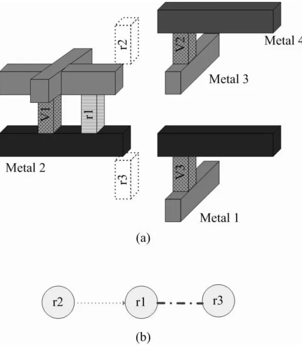
Before constructing the directed conflict graph, we have to know some features about the nodes and edges in directed conflict graph. Each node represents the original via or the feasible via, and each edge has capacity and cost. We break edges into two sets: solid and dash; solid edges connect single via with its related feasible via or connect feasible vias which conflict with each other on the same layer, and
dash edges connect conflict feasible vias on different via layers. Hence a node will have two dashed edges at most, one is for upper layer and the other one is for lower layer, like the example shown in Figure 3.1, r1 conflicts with r2 for upper layer and r1 conflicts with r3 for lower layer. Hence r1 has two dashed edges in our directed conflict graph.
The steps of the construction of the directed conflict graph is shown as follows: Step 1. Dummy node ”s” and dummy node ”t” are added as ”source” and ”sink”. Step 2. Connect ”s” to original via node with edge assigned capacity 1, zero cost. Step 3. Connect original via node to its related feasible node with edge assigned capacity 1 and non-zero(x) cost.
Step 4. Connect feasible nodes each of which conflict with each other on the same layer with solid edge with capacity 1 and zero cost. Assign the direction arbitrary. Step 5. Connect feasible nodes each of which conflict with each other on different layers with dash edge with capacity 1 and non-zero(y) cost.
Step 6. Assign color green(thin) to the dash edge connecting two nodes that these two nodes without any other dash edge. Assign the direction of this green edge arbitrary.
Step 7. For each node with two dash edge, assign color green(thin) to the dash edge of which original via node with minimum out-degree. Assign direction to the green dash edge arbitrary. Assign red(thick) edge to the other dash edge, this red(thick) edge represents the potential conflict of the solution.
Step 8. Connect the node with green edge and rest of feasible node to node ”t” with edge assigned capacity 1, zero cost.
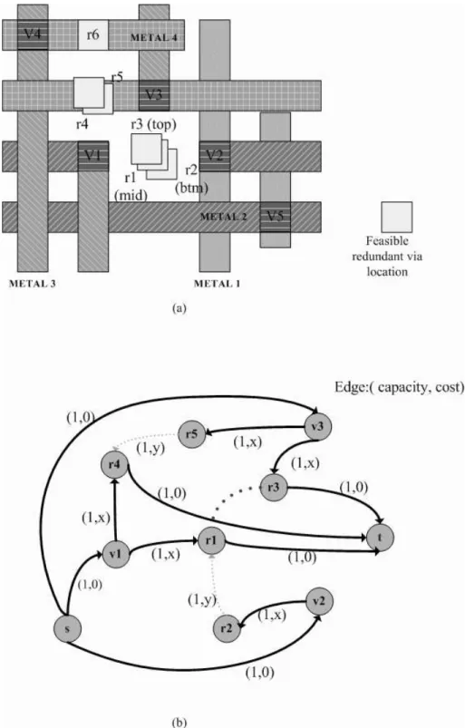
Figure 3.2 shows that the original design and its directed conflict graph. In Figure 3.2(a), V4 has one feasible via without conflict with others and only V5 has no feasible vias, so we will not put them into our directed conflict graph. In Figure
Figure 3.1: An example of conflict condition. (a)Layout solution. (b)Simple directed conflict graph.
3.2(b), V3 has two feasible nodes, r3 and r5, but V2 only has one feasible node r2. Therefore, out-degree of V2 is lower than out-degree of V3, so we assign (r2,r1) green(thin) color and assign (r1,r3) red(thick) color. Last, make (r1,r3) thicker than other green edges.
Considering our directed conflict graph G(V,E), and a maximum set V’ of G is a maximum vertex set such that, ∀ vi, ri∈ V’, (vi, ri)∈ E(solid edge). A vertex vi of G represents the single via and a vertex ri of G represents a feasible double via, hence, (vi,ri) represents a double-cut via. Therefore, we want to find the maximum number of the pairs of (vi,ri) for the redundant via insertion problem, so the maximum set of G is a set having the maximum number of double-cut vias. Hence, we can formulate our Problem 2.1 as the new Problem 3.1.
Problem 3.1 Given a detailed routing solution, without re-routing any signal net, constructing this solution to our directed conflict graph. Then find out the maximum set of the directed conflict graph. Any pair of vertexes in the maximum set represents the single via each of which can be replaced by feasible double-cut via.
In the next section we will show how we find the maximum set of the directed conflict graph.
3.2
Minimum Cost Maximum Flow (MCMF)
We use a linear program, Minimum Cost Maximum Flow (MCMF), to solve the
problem 3.1 on our directed conflict graph, and we can find out the optimal solution
in polynomial time in most designs. The details are presented in the following subsections.
Figure 3.2: Construction of directed conflict graph. (a)Routing layout. (b)Resulting directed conflict graph.
3.2.1
Maximum Flow
We are given a directed graph G(V,E) in which each edge (u,v)∈ E has a nonnegative capacity cap(u,v)≥ 0, and two distinguished vertices, a source s and a sink t. A maximum flow is a flow that not only satisfies three properties, capacity constraints, skew symmetry and flow conservation, but also maximizes the flow value which is the total flow coming out of the source. The maximum flow problem can be expressed as a linear program, and the value of a flow is also a linear function. Assuming that cap(u,v) = 0 if (u,v) /∈ E, then the maximum flow problem is as follows:
Maximize X v∈ V
f (s, v) (3.1)
Subject to
f (u, v) ≤ cap(u, v) f or each u, v ∈ V, (3.2)
f (u, v) = −f (v, u) f or each u, v ∈ V (3.3) X
v∈ V
f (u, v) = 0 f or each u, v ∈ V − {s, t} (3.4)
3.2.2
Minimum Cost Flow
Given a directed graph G(V,E) in which each edge (u,v)∈ E has, in addition to a capacity cap(u,v), a real valued cost c(u,v). If we send f(u,v) units of flow over edge (u,v), we incur a cost of c(u,v)f(u,v). We wish to send X units of flow from s to t in such a way that the total cost incurred by the flow, P(u,v)∈ Ec(u, v)f (u, v), is
minimized. This problem is known as the minimum cost flow problem. We also can express the minimum cost flow problem as a linear program that is similar to the one for the maximum flow problem with the additional constraint, the value of the flow be exactly X units. Here is the minimum cost flow problem:
Subject to
f (u, v) ≤ cap(u, v) f or each u, v ∈ V (3.6)
f (u, v) = −f (v, u) f or each u, v ∈ V (3.7) X v∈ V f (u, v) = 0 f or each u, v ∈ V − {s, t} (3.8) X v∈ V f (s, v) = X (3.9)
3.2.3
Solving the Problem
From the our problem 3.1, we want to find the maximum number of the pairs of (vi,ri) from our directed conflict graph, and if two feasible via nodes are the endpoints of a edge, only one of them will be chosen because of the conflict. We assign all the edges in directed conflict graph capacity 1, and all the single vias nodes connect with source s, if f (s,vi) equal to 1 then their must be a f (vi,ri) also equal to 1. This condition represents we choose single via vi to be replaced by a double-cut via (vi,ri). A single via vi has at most four feasible double vias, and have to choose the less conflict feasible double via because of higher redundant via insertion rate. We can give lower cost for less conflict and higher cost for high conflict. Therefore, we only have to select the edge which has lower cost from single via, the other endpoint of the edge is the feasible via node, to avoid conflict with others.
Hence, we can use the minimum cost flow to select less conflict feasible via nodes and maximum flow to find the maximum number of double-cut vias simultaneously. Therefore we solve problem 3.1 by the Minimum Cost Maximum Flow.
Before running MCMF, we should remove red edges first because that the red(thick) edge is the potential conflict of the solution. If there was a red edge between the
selected feasible via nodes, these two nodes are conflict. Hence we should move one of the nodes to another feasible via node without conflict by breadth-first-search (BFS), if no other feasible via node without conflict, one conflict feasible via node would be removed. However, if we assign high cost on the edge into the node that had red edge, the possibility of conflict would be reduced.
Actually, if the cost of green(thin) edge is y and the cost of the edge from single via node to feasible via node without red(thick) edge is x, then the cost of the edge from single via node to feasible via node with red(thick) edge is at least x+y+1. Therefore, this cost condition can reduce the possibility of conflict.
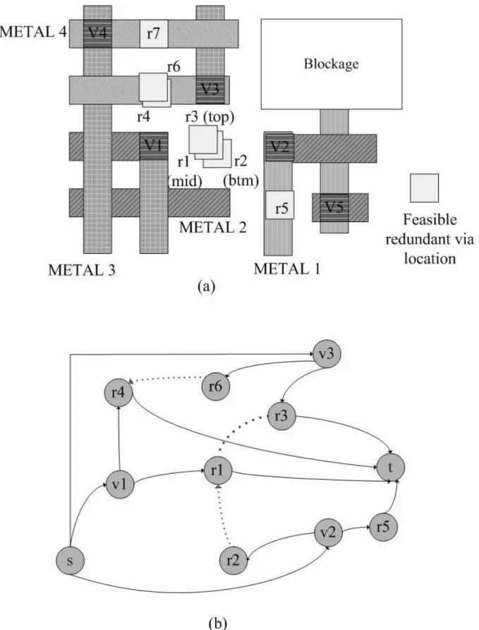
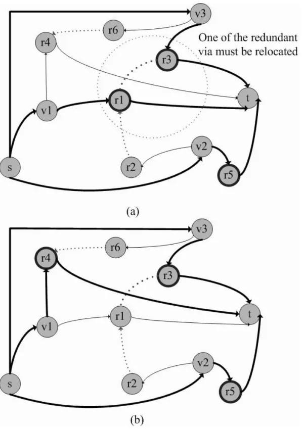
Figure 3.3(a) shows another design and Figure 3.3(b) shows the related directed conflict graph. Figure 3.4(a) is a solution after MCMF, but there is a conflict between node r1 and node r3 because of red edge. We solve the conflict by choosing r4 instead of r1, then the optimal solution is shown in Figure 3.4(b).
Figure 3.3: Another example of construction of directed conflict graph. (a)Routing layout. (b)Resulting directed conflict graph.
Figure 3.4: Two solutions from problem 3.1 of Figure 3.3. (a)Conflict solution because r1 conflicts with r3. (b)Best solution.
Chapter 4
ECO for Changing Routing Layout
An engineering change order (ECO) is a request to make design changes, typically during the chip implementation cycle. ECO changes are almost always unavoidable and updating the design with an incremental change not only saves considerable effort in realizing the design but also reduce the possible of introducing new errors into the design. The ECO problem involves the ability to specify the incremental design changes, implement the design changes and update all design databases to reflect the changes.
If engineers need to change only a small portion of the layout solution, involving adding a via or removing a via, running the all processes include directed conflict graph construction and MCMF to find the maximum number of double-cut vias is very time-consuming. The efficient way is to find the affected set and update the maximum number of double-cut vias during this set. [6] has already presented an incremental algorithm for maximum flow, but they do not consider minimum cost flow. Note that sometimes adding (removing) a single via may not change the the solution of the redundant via insertion, because the feasible via of this single via may conflict with another feasible vias of different single via.
4.1
An Incremental Algorithm for Updating the
Solution
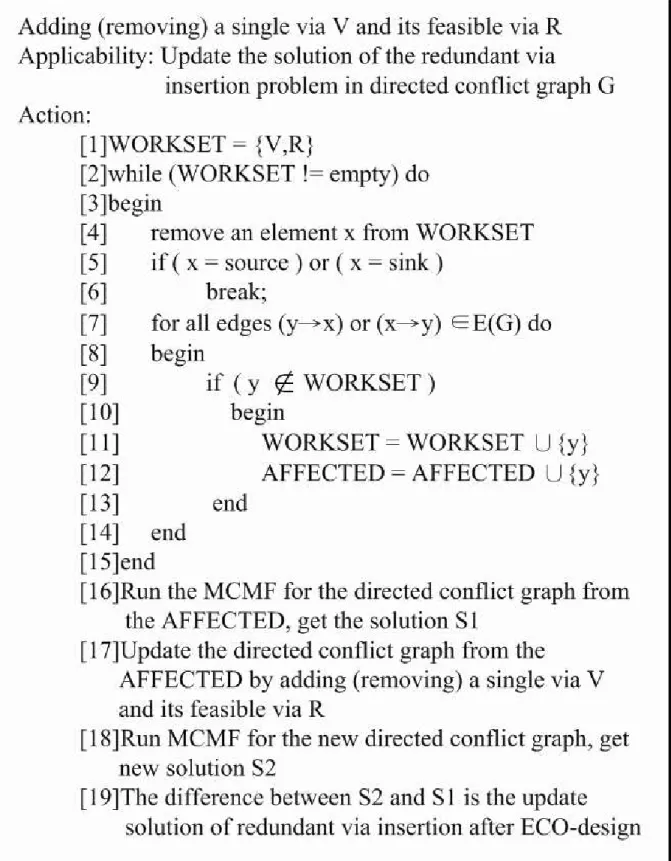
Here we present an incremental algorithm which updating the solution of the redun-dant via insertion problem after a single via is added or removed. When a single via is added or removed, its feasible via should be added into the directed conflict graph or its feasible via should be removed from directed conflict graph. Hence, there may exist some single vias or feasible vias which are affected after adding(removing) single vias or feasible vias. We find the affected set in our directed conflict graph first and then update the maximum number of double-cut vias during this set later.
When a single via Vi is added (removed), we put the single via and its feasible via into the work set, which is for finding the affected vias. Then finding the affected single vias and feasible vias from the work set in our directed conflict graph, and also put the affected single vias and feasible vias into work set and affected set which contains all the affected vias. If there is no affected single vias and feasible vias, we chalk up the maximum number S1 of redundant via insertion problem
among these affected single vias. Later, we update the directed conflict graph by adding(removing) the single via Vi and its related feasible vias, and use MCMF to get the new solution S2 of redundant via insertion problem among these affected
vias. Therefore, the difference between S1 and S2is the update solution of redundant
via insertion problem after ECO-design. The incremental algorithm is summarized in Figure 4.1.
Let us now analyze the complexity of finding the affected vias. The loop in lines 2-15 of our incremental algorithm performs exactly |AFFECTED| iterations. The iteration corresponding to vertex x takes O|Find(x)| time in case of our in-cremental algorithm. Therefore, the running time of finding the affected vias are O(Px∈AF F ECT ED | F ind(x) |).
Figure 4.1: Overview of the incremental algorithm for update the redundant via insertion porblem.
Chapter 5
Experimental Results
We implemented our approach in the C++ Programming language and the platform is on Linux based machine with two CPUs and 14GB memory.
The set of test cases we used is from [8]. Table 5.1 shows the detail information of the set of test cases; for each test case, the first column gives the test circuit name, ”Size(µm)” shows the layout dimension, ”#Nets” gives the number of nets, ”#I/Os” shows the number of pins, ”#Vias” gives the total number of single vias, ”#D-Vias” shows the number of single vias each of which has at least one feasible double-cut via, and ”#Layers” gives the number of metal layers used. Finally, ”#Objects” gives the total number of layout objects including pins, vias, blockages and wire segments.
Table 5.1: The information of five test cases [8].
Case Size(µm) #Nets #I/Os #Vias #D-Vias #Layers #Objects C1 350.000*350.000 4309 20 24594 17522 5 218215 C2 419.433*413.28 5252 211 41157 28591 5 268669 C3 799.124*776.16 18157 85 127059 91727 5 933852 C4 691.272*680.400 17692 415 151912 102347 5 943073 C5 1383.482*1375.92 44720 99 357386 255301 5 2851612
the conflict graph are shown in Table 5.2. ”#Nodes” gives the number of nodes in the conflict graph (i.e., the number of feasible double-cut vias) and ”#Edges” shows the number of conflict edges.
Table 5.2: Statistics on conflict graphs.
Case #Nodes #Edges C1 38829 33990 C2 61369 50430 C3 200051 169407 C4 200311 147353 C5 529039 415765
We break the conflict graph into two sets: double vias set and conflict set. Then we constructed our directed conflict graph from conflict set of each case. Table 5.3 shows the related results. ”#D-CUT” shows the number of single vias each of which has at least one redundant via location without any conflict with oth-ers, ”#D Nodes” gives the number of the nodes in our directed conflict graph, ”#D Edges” shows the number of solid edges and green edges, and ”#Red Edges” gives the number of red edges in out directed conflict graph. Finally, ”CPU1(s)” shows the related execution time. We can find that the sizes including nodes and edges of our directed conflict graphs are very small; therefore, it is very good for the multi-core/parallel computation.
Table 5.3: Statistics on directed conflict graphs.
Case #D-CUT #D Nodes #D Edges #Red Edges CPU1(s) C1 17396 256 382 2 0.88 C2 28414 361 541 4 1.61 C3 91152 1177 1775 16 6.10 C4 101108 2515 3787 53 14.36 C5 253440 3806 5747 45 16.92
in [8]. The results are shown in Table 5.4. In the table, ”CPU2(s)” gives the execution time for running minimum cost maximum flow, ”#R-Vias” shows the number of double-cut vias found from directed conflict graph after running minimum cost maximum flow, ”#D-Total” gives the number of total double-cut vias from the original design, and ”Rate(O)” is equal to ”#D-Total” divided by ”#D-Vias” shown in Table 5.1. ”H2K” shows the number of inserted double-cut vias by H2K, ”Rate(H2K)” is equal to ”H2K” divided by ”#D-Vias”.
Table 5.4: The experimental results on test cases: Comparison for post-routing redundant via insertion with H2K [8]. We insert more redundant vias than H2K on C4 circuit.
Case CPU2(s) #R-Vias #D-Total Rate(O) H2K Rate(H2K) C1 0.02 65 17461 99.65% 17461 99.65% C2 0.03 93 28507 98.13% 28507 98.13% C3 0.05 309 91461 99.71% 91461 99.71% C4 0.11 658 101766 99.43% 101765 99.43% C5 0.42 988 254428 99.66% 254428 99.66%
From Table 5.4, we can see that our algorithm inserts more redundant vias than H2K on C4 circuit, and inserts the same number of redundant vias on the other circuits. So our algorithm is a better solution to find the optimal solution. And From Table 5.5, our algorithm also works very fast. We also list the CPU time of H2K [8] including the time spent by graph construction for reference. [8] implemented H2K in C++ language running on a Linux based machine with 2.4G processor and 2GB memory.
Table 5.6 shows the timing compare between full process and incremental al-gorithm after ECO-design on C5 circuit. ”#Changes” represents the number of changes after ECO-design, ”#E-Total” gives the number of total double-cut vias after ECO-design, ”CPUF(s)” represents the total runtime includes directed graph construction and MCMF after ECO-design to solve the redundant via insertion
prob-Table 5.5: CPU time of our algorithm and H2K [8] from different platform. Our input file is the conflict graph from [8] and their input file is the layout solution.
Case Total Run time: CPU1(s)+CPU2(s) CPU(s) H2K
C1 0.88 32
C2 1.64 43
C3 6.15 192
C4 14.47 203
C5 17.34 710
lem, and ”CPUI(s)” gives the runtime of incremental algorithm includes finding the affected set and MCMF to update the solution of the redundant via insertion after ECO-design. On average, our incremental algorithm obtains 24X runtime speedup.
Table 5.6: The timing comparison between full process and incremental algorithm after ECO-design on C5 circuit. CPUF(s) represents the total runtime includes directed graph construction and MCMF after ECO-design to solve the redundant via insertion problem. CPUI(s) gives the runtime of incremental algorithm includes finding the affected set and MCMF to update the solution of the redundant via insertion after ECO-design.
#Changes #E-Total CPUF(s) CPUI(s) 10 992 17.11 1.01 15 988 17.28 1.24 15 994 17.28 1.77 20 989 17.30 2.74 20 994 17.30 2.74 Comp. 10.65 1
Chapter 6
Conclusion
In this thesis, we propose a graph construction algorithm to solve the redundant via insertion problem to reach a higher rate for improving the manufacturing yield. First we use our graph construction algorithm to construct the directed conflict graph from the given routing result to consider all the vias of a design simultaneously. Then we use minimum cost maximum flow to find the maximum number of redundant vias from the directed conflict graph. Experimental results show that our algorithm can get almost optimal solution for improving the redundant via insertion rate in polynomial time. In addition, after ECO for the whole design, we can efficiently update the solution by incremental algorithm. The experimental results show it is very efficient for updating the optimal solution.
Bibliography
[1] “Taiwan Semiconductor Manufacturing Company (TSMC)”. In Referecne Flow
5.0 and Reference Flow 6.0.
[2] D. Abercrombie. “Via Doubling Can Help to Stem Yield Loss”. In EE Times, Oct. 2005.
[3] G. A. Allan. “Targeted Layout Modifications for Semiconductor Yield/Reliability Enhancement”. In IEEE Transactions on Semiconductor
Manufacturing, volume 17, pages 573–581, Nov. 2004.
[4] H.-Y. Chen, M.-F. Chiang, Y.-W. Chang, L. Chen, and B. Han. “Novel Full-Chip Gridless Routing Considering Double-Via Insertion”. In Proc. of Design
Automation Conference, pages 755–760, 2006.
[5] C. Christiansen, B. Li, J. Gill, R. Filippi, and M. Angyal. “Via-Depletion Electromigration in Copper Interconnects”. In IEEE Transactions on Device
and Materials Reliability, volume 6, pages 163–168, Jun. 2006.
[6] S. Kumra and P. Gupta. “An Incremental Algorithm for the Maximum Flow Problem”. In Proc. of Journal of Mathematical Modelling and Algorithms, volume 2, pages 1–16, 2003.
[7] K.-Y. Lee and T.-C. Wang. “Post-Routing Redundant Via Insertion and Line End Extension with Via Density Consideration”. In Proc. of ICCAD, pages 633–640, 2006.
[8] K.-Y. Lee and T.-C. Wang. “Post-Routing Redundant Via Insertion for Yield/Reliability Improvement”. In Proc. of ASPDAC, pages 303–308, 2006.
[9] F. Luo, Y. Jia, and W.-M. Dai. “Yield-Preferred Via Insertion Based on Novel Geotopological Technology”. In Proc. of ASPDAC, pages 730–735, 2006.
[10] T. Pompl, C. Schlunder, M. Hommel adn H. Nielen, and J. Schneider. “Practical Aspects of Reliability Analysis for IC Designs”. In Proc. of Design Automation
Conference, pages 193–198, 2006.
[11] S. Raghvendra and P. Hurat. “DFM: Linking Design and Manufacturing”. In
Proc. of the International Conference on VLSI Design, pages 705–708, 2005.
[12] L. K. Scheffer. “Physical CAD Changes to Incorporate Design for Lithography and Manufacturability”. In Proc. of ASPDAC, pages 768–773. Jan. 2004.
[13] J. G. Xi. “Improving Yield in RTL-to-GDSII Flows”. In EE Times, Jul. 2005.
[14] G. Xu, L.-D. Huang, D. Z. Pan, and M. D. F. Wong. “Redundant-Via Enhanced Maze Routing for Yield Improvement”. In Proc. of ASPDAC, volume 2, pages 1148–1151, Jan. 2005.
[15] H. Yao, Y. Cai, X. Hong, and Q. Zhou. “Improved Multilevel Routing with Redundant Via Placement for Yield and Reliability”. In Proc. of Great Lakes
Symposium on VLSI, pages 143–146, 2005.
[16] Y. Zorian, D. Gizopoulos, C. Vandenberg, and P. Magarshack. “Guest Editors’ Introduction: Design for Yield and Reliability”. In IEEE Trans on Design &

![Figure 2.1: Illustration of double-cut via types [8].](https://thumb-ap.123doks.com/thumbv2/9libinfo/8746766.205119/15.918.233.663.156.278/figure-illustration-of-double-cut-via-types.webp)
![Figure 2.2: An example of conflict graph construction [8]. (a)Routing layout.](https://thumb-ap.123doks.com/thumbv2/9libinfo/8746766.205119/17.918.231.657.403.1038/figure-example-conflict-graph-construction-routing-layout.webp)
![Table 5.1: The information of five test cases [8].](https://thumb-ap.123doks.com/thumbv2/9libinfo/8746766.205119/31.918.125.855.914.1052/table-information-test-cases.webp)
