Design and implementation of fault-tolerant and cost
effective crossbar switches for multiprocessor
systems
K.Wang C.-K. WU
Abstract: Two general crossbar switch models are
proposed: the modified one-sided crossbar switch and the ripple K one-sided crossbar switch. They both balance cost and reliability, where cost is expressed in terms of crosspoint count or area. The two-sided crossbar switch and the one-sided crossbar switch are two cases of these structures. These structures provide choices for compromising structures between the two-sided crossbar switch and the one-sided crossbar switch. The effective bandwidths of these four crossbar switches are simulated. Simulation with VHDL has been performed to verify the functionality of each crossbar system. Synthesis has also been conducted to evaluate delay and area for each crossbar design. Experimental results demonstrate that the two general models of crossbar switches are cost-effective in terms of reliability and crosspoint count (or area) without reducing their effective bandwidths. The work promotes the use of the crossbar switch as an interconnection network for multiprocessor systems to enhance system performance and reliability with low cost.
1 Introduction
With the great progress in VLSI technology, designing a better multiprocessor system has been mostly focused on attaining high parallel computation power [l]. A
key component in a high-performance multiprocessor system is the interconnection network between proces- sors and memory modules or among processors. The bandwidth and the latency of the interconnection net- work are two important factors in the performance evaluation of the multiprocessor system [3]. In a shared memory multiprocessor system, there are several struc- tures for the interconnection network, such as single bus, multiple-bus, crossbar switch, multiport memory and multistage interconnection network [4]. For a crossbar switch, all possible one-to-one simultaneous connections are allowed between processors and mem- ory modules. However, crossbar switch costs grow with 0 IEE, 1999
IEE Proceedings online no. 19990240 DOL 10.1049/ip-cdt: 19990240
Paper first received 12th July 1996 and in revised form 1 lth March 1997 The authors are with the Department of Computer and Information Sci- ence, National Chiao Tung University, Hsinchu, Taiwan 30050, ROC
O(NM), where N is the number of processors and M is the number of memory modules. The crossbar switch network is used for communications switching and for computer interconnection. It is a nonblocking network. In the two-sided crossbar switch, there is only one path between every pair of processor and memory module. Despite better performance and easier controllability, its one-path uniqueness makes it susceptible to mal- functions. The malfunction of any crosspoint in the two-sided crossbar switch will disjoint a processor- memory module pair.
In normal conditions, the manipulation of high-qual- ity components and design techniques does not ade- quately decrease the possibility of system failure [6, 71. Therefore, fault-tolerance techniques must be provided to deal with faults in the system. A modern switching
system must be capable of diagnosing the occurrence of hardware faults in the switching network and the con- trol system. Once a fault is detected, the switching sys- tem automatically reroutes traffic through redundant built-in hardware or via other switching facilities [ 5 ] .
Since the high cost of the crossbar switch in terms of crosspoint count or area may be expected, it is desira- ble that the fault-tolerant design of the crossbar switch is cost-effective. In this paper, we propose two fault- tolerant crossbar switches which balance cost and relia- bility without sacrificing their effective bandwidths. Simulation with VHDL (VHSIC hardware description language) [S, 91 has been performed to verify the func- tionality of each design. Synthesis has also been con- ducted to evaluate area and delay.
bus lines
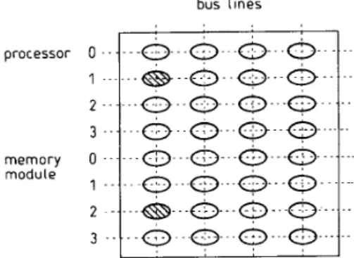
Fig. 1 One-sided crossbar switch with 4 bus-lines and 8 port-lines 2 Existing approaches
2.1 Original one-sided crossbar switch
A traditional one-sided crossbar switch provides better
fault-tolerance ability by providing multiple paths to IEE Proc.-Comput. Digit. Tech., Vol. 146, No. I , January I999 50
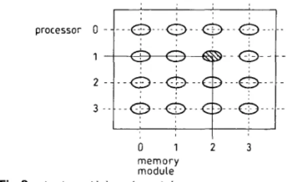
establish a connection between any pair of terminals [lo-121. A one-sided crossbar switch consists of a set of port-lines and a set of bus-lines situated at right angles to each other, with crosspoint switches located at the points of intersection. In the one-sided crossbar switch, a connection between two ports is set up by activating a pair of crosspoint switches, instead of one in the two- sided crossbar switch. For example, in a 4 x 4 one- sided crossbar switch, a connection between processor 1 and memory module 2 is as shown in Fig. 1. A circu- lar cell represents a crosspoint, and a shaded circular cell indicates that the crosspoint has been granted for the connection. Fig. 2 shows the same case for a 4 x 4 two-sided crossbar switch.
I
I I
0 1 2 3
memory module
4 x 4 two-sided crossbar switch
Fig.2
There is more than one way for a connection to be made between a processor and a memory module in the one-sided crossbar switch. There are B (in this example, B = 4) different ways for a connection between any processor-memory module pair when there are B buses (bus-lines). This design offers supe- rior fault-tolerance ability to the two-sided crossbar switch, as any unused path (bus-line) can be selected for replacing a faulty path between two ports in the one-sided crossbar switch. However, the crosspoint count of the one-sided crossbar switch is twice as many as that of the two-sided crossbar switch. Note that B should be chosen to be equal to min(M, N). If B is greater than min(M,
N),
the bandwidth will not be improved and is still the same as that when B equals min(M, N). If B is less than min(M,N),
it will not sat- isfy the nonblocking characteristic of the crossbar switch.2.2 Bandwidth analysis
There have been many studies of the performance eval- uation of the traditional two-sided crossbar switch. Youn and Chen [13] proposed a comprehensive model to analyse the bandwidth. We discuss and analyse the traditional two-sided crossbar switch to compare with our fault-tolerant designs. The following assumptions [13] are made.
(i) There are N processors and M memory modules. (ii) Let min(M,
N)
= S and B = S.(iii) All processors are synchronised.
(iv) The processor requests are independent, and a processor requests each memory module with equal probability.
(v) The cycle time is constant and the same for all processors and memory modules.
(vi) A processor issues a new request in each cycle
IEE Pror.-Coniput. Digit. Tech., Vol. 146, No. 1, Junuary 1999
according to a predetermined request rate p , after receiving a memory service.
(vii) The rejected requests are discarded.
(viii) The probability that processor p i requests memory mi is (plM) for all i and j .
First, we show the bandwidth ( B W ) of the traditional two-sided crossbar switch is
BW =
s
(1 - (1 - p / M ) N ) (1)This is because (1 - p/WN represents the probability
that none of the N processors requests any specific memory module access. Therefore, 1 - (1 - P I M ) ~ is
the probability that at least one processor requests a specific memory module access, and S(l - (1 ~ P I M ) ~ )
is the expected number of busy memory modules. Next, we analyse the bandwidth of the one-sided crossbar switch. The topology of the one-sided crossbar switch is similar to that of the multiple-bus network. It is conceivable that the analysis of the one-sided cross- bar switch is similar to that of the multiple-bus net- work [14]. The only difference is that the nonblocking property of the one-sided crossbar requires B = min(M,
N)
= S. In addition, it is impossible to have more than B of the M memory modules accessed. The assump- tions are the same as those for the traditional two-sided crossbar switch. The bandwidth analysis can be treated in two parts; the memory part and the bus part. 2.2.7 Memory part: The result from the two-sided crossbar switch can be used, i.e. the probability that at least one processor requests a specific memory module access is given by4 = 1 - (1 - p / M ) N (2)
2.2.2 Bus part: The probability that exactly i of the
M memory modules accessed is given by
(3)
From eqn. 3 , the bandwidth can be derived from the expected number of bus-lines in use during a bus cycle:
B S
BW =
Cif(2)
=Cif(2)
i=l i=l
(4)
3 Design approaches
3.7 Modified one-sided crossbar switch
How to balance cost and reliability without abruptly decreasing the effective bandwidth is key to the design of a fault-tolerant one-sided crossbar switch. The mod- ified one-sided crossbar switch consists of B bus-lines to connect N processors to M memory modules. To maintain the feature of nonblocking, processors and memory modules should be connected to bus-lines in the following manner. When N 2 M , each of these bus- lines is connected to all N processors, but only to a subset of Mlg memory modules, where g is the number of memory groups. Thus, the memory modules are sep- arated into g groups, and in each group the memory modules are connected to the same Blg bus-lines.
Fig. 3 shows an example modified one-sided crossbar switch with eight processors, four memory modules, four buses, and g = 2. When M > N , the roles of proc- essors (N) and memory modules ( M ) are interchanged.
Note that both B and A4 (or B and N) should be divisible by g.
3.2 Ripple K one-sided crossbar switch
We propose another fault-tolerant one-sided crossbar switch. We call it the ripple K one-sided crossbar switch. The rules of either full connection or partial connection to the bus-lines for processors and memory modules should still be obeyed. Fig. 4 shows an exam- ple ripple K one-sided crossbar switch with four proces- sors, four memory modules, and four buses, where K is equal to 3. We use Fig. 4 to describe how to construct a ripple K one-sided crossbar switch as follows.
( i ) Each memory module is connected to a constant number K of bus-lines.
(ii) The starting crosspoint locations between adjacent memory modules have one bus-line number difference. (iii) For each memory module, the assignment of cross- point switches to bus-lines is continuous and the two boundary bus-lines are considered as adjacent.
3 .... bus Lines
Fig. 3 Mod8ed one-sided crossbar switch
N = 8, M = 4. B = 4 , g = 2 -...: ... -.:- ... 1
...a...
.. processor 0 . . ..o.
.-0
.-0
...c)
...1 ...
0
....c>...Q.-.O.--.--
2 ...
0...o...a...&
...3
...
memory 0
.a..
&.
....;..
...1 ... : ...
Q...Q...O.-.
2 .....a..
.. ..:... ...&.
..&.
...3 . .
~ ~ ~ . a .
..a
... L . ....o-
... module3.3 Comparison among three one-sided crossbar switches
The crosspoint count comparison among the three one- sided crossbar switches is summarised in Table 1. In terms of crosspoint count, the one-sided crossbar has the highest cost when g > 1 and K < B, and the costs of the modified crossbar switch and the ripple K cross- bar switch are identical if K = Big . Note that there are two active crosspoints for these three designs. The modified one-sided crossbar switch and the ripple K 52
...
crossbar switch are equivalent in terms of crosspoint count when K = Blg. In addition, these two switches are two general models of the crossbar switch. The two-sided crossbar switch and the one-sided crossbar switch are just two special cases of the above two gen- eral models. Thus, the modified one-sided crossbar switch and the ripple K one-sided crossbar switch can be reduced to the two-sided crossbar switch if g = B and K = 1, respectively. In addition, the modified one- sided crossbar switch and the ripple K one-sided cross- bar switch are equivalent to the one-sided crossbar switch if g = 1 and K = B, respectively.
Table 1: Crosspoint count comparison among the three one-sided crossbar switches
Crossbar switch Crosspoint count
B ( N + Nn B ( N + M / g ) , i f N r M ; B ( M + N / g ) , i f M > N B ( N + M , i f N > M ; B ( M + M , i f M > N One-sided Modified Ripple K
Let us use an example to illustrate the first situation. Fig. 5 can be considered as a modified one-sided cross- bar switch with g = B, and also as a ripple K one-sided crossbar switch with K = 1. Fig. 5 can also be consid- ered as a transformation of a two-sided crossbar switch. Note that the illustration of the second situa- tion is quite obvious.
processor 0 ..
1 .. ..
2 .. ..
3 ..
memory 0 ..
...a
... ~ ... ~ ... : ...moduLe 1 ...
t :
&
.... .; ...: I
i.. ...3.4 Bandwidth analysis
Since the four crossbar switches (two-sided, one-sided, modified and ripple K ) are all strictly nonblocking net- works, their bandwidths are the same. For illustration, we only derive the bandwidth of the modified one-sided crossbar switch here. If the B bus-lines are grouped into g group, eqn. 3 is rewritten as
Consequently, the bandwidth can be written as
B l a SI4
Although the bandwidths of the four crossbar switches are identical, we evaluate the bandwidth of each cross- bar switch in variance of different parameters via simu- lation. Owing to structural differences, the conditions of parameters in each switch model are not the same, which is shown in Table 2, where pos represents a
request
Table 2: Conditions of parameters in the four crossbar switch models
arbiter switch
priority-check path-setup demultiplexing crosspointprray
1c ---c oddrm
-
*-+ data,c
--
A1
t -
Model Parameters Conditions
Two-sided crossbar P, M, N P s 1
One-sided crossbar Modified one-sided crossbar Ripple K one-sided crossbar
P, Mr N, B p, M, N, B, g p, M, N, B, K p s 1, B = m i n ( M , M p s 1, B l g E pos, B = min (M, M , 1 s g s B p s 1, B = m i n ( M , M, 1 s K s B
Table 3: Bandwidth simulation results of the four crossbar switches in variance of M and p Number of memory modules Probability p 0.5 1.0 0.5 1.0 0.5 1.0 0.5 1.0 0.5 1.0 Two-sided 0.88 1.50 1.66 2.73 3.23 5.25 4.80 7.78 6.37 10.30 One-sided 0.88 1.50 1.66 2.73 3.23 5.25 4.80 7.78 6.37 10.30 Modified 0.88 1.50 1.66 2.73 3.23 5.25 4.80 7.78 6.37 10.30 Rioole K 0.88 1.50 1.66 2.73 3.23 5.25 4.80 7.78 6.37 10.30 M = 2 M = 4 M = 8 M = 12 M = 16
positive integer. In the following simulation, without a loss of generality, the values of M and N are set equal. To ensure the nonblocking feature of crossbar switches and provide the maximum possible connections, B
should be set equal to min(M, N). The request rate @) is set to 1 and 0.5, respectively. In Table 3 , we show the bandwidths of the four crossbar switches under differ- ent M and p values. The results verify that the band- widths of these four crossbar switches are identical for the same case.
4 Simulation and synthesis 4.
I
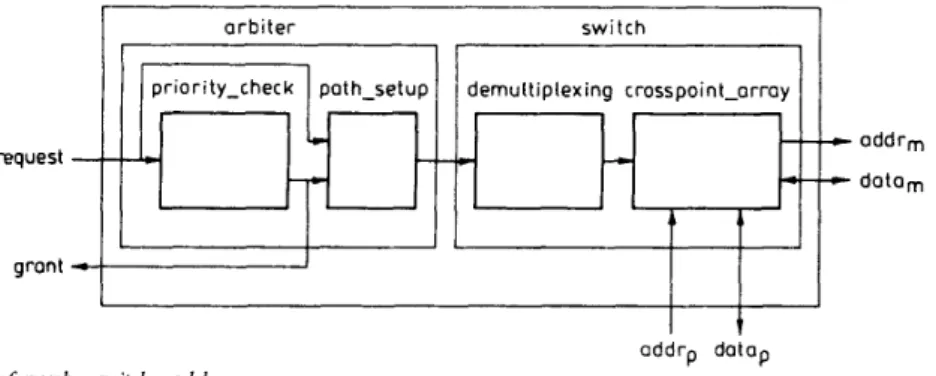
To verify each crossbar switch model, we design a pro- totype for each crossbar switch. Each of these four pro- totypes includes an arbiter and a switch. Fig. 6 shows the block diagram of the crossbar switch model. Addrp (data,) and addr, (data,) are two sets of address (data) lines connected to the corresponding processors and the selected memory modules, respectively. Request is a set of request signals, including the read/write modes and the requested memory module numbers. Grant is a set of signals indicating that the selected processors have right to access their requested memory modules. If a grant signal is activated, the corresponding proces- sor will output or input data to and from the requested memory module via the crossbar switch by issuing a write or read request, respectively.
The two major functions of the arbiter are resolving conflicts and arbitrating paths. Therefore, the arbiter includes priority-check and path-setup to implement
Design hierarchy and VHDL simulation
IEE Proc.-Comput. Digit. Tech., Vol. 146, No. I , Junuary 1999
oddr, doto, data,
oddr, addrS data,
Fig. 7 bgiccrl structure of crosspoint
these two functions, respectively. The switch consists of
demultiplexing and crosspoint-array. The function of demultiplexing is demultiplexing the control signals of the switch, and crosspoint-arruy is a two-dimensional matrix of crosspoints. Fig. 7 shows the logical structure of a crosspoint. The crosspoint has four address ports (addr,, ad&,$,, addr,, and addr,) and four data ports (data,, d a ta ,, duta,, and data,). It consists of two switching boxes (addr-box and datu-box) for address and data transfers. Addr, and datu, are two control lines to control the two switching boxes for address 53
lines and data lines set-ups, respectively. The four different crossbar switches have been described with VHDL, and their functionalities have been verified via VHDL simulation.
Table 4: Area comparison of the four crossbar switches
Area Arbiter Switch Total
4 x 4 two-sided 963 5604 6567
4 x 4 one-sided 3486 11704 15190
4 x 4 modified, g = 2 3486 9144 12630
4 x 4 ripple, K = 3 3486 10424 13910
~ ~~
Table 5: Delay comparison of the four crossbar switches
Delay Arbiter Switch Total
4 x 4 two-sided 42.77 11.83 54.60
4 x 4 one-sided 50.75 13.20 63.95
4 x 4 modified, g = 2 50.75 13.20 63.95
4 x 4 r i m l e , K = 3 50.75 13.20 63.95
4.2 VHDL synthesis
We show some VHDL synthesis results from the four different crossbar switches. Table 4 gives the area com- parison of the four crossbar switches. The switch takes up most of the area in each design. Both the modified one-sided crossbar switch and the ripple K one-sided crossbar switch use less area than the one-sided cross- bar switch. Table 5 shows the delay comparison of the four crossbar switches. Owing to algorithm complexity, arbiter takes up most of the delay in the four designs. Note that the delays of the three one-sided crossbar switches are the same, since setting up a connection requires two crosspoints anyway.
5 Reliability and cost-effectiveness analysis We also evaluate the reliability and the cost-effective- ness of the three fault-tolerant one-sided crossbar switches in terms of reliability and crosspoint count (or area). The two-sided crossbar switch is not analysed, since it does not have a fault-tolerance ability. The fol- lowing definitions are used in our analysis:
Nc A ,
A,
P R,(t)
= total number of crosspoints
= area of a crossbar switch
= failure rate of a crosspoint (in units of failures per hour [7])
= request rate of a processor
= reliability of a crosspoint is expo- nentially distributed with a constant failure rate A,, i.e. ~ , ( t ) = e-*ct
Q<i) = survival probability that a given connection set can be realised under i faulty crosspoints in the crossbar switch
R(t) = reliability function of a crossbar switch
R(t)IN, (R(t)IA,) = figures of merit for cost effective- ness
The reliability R(t) of a fault-tolerant one-sided cross- bar switch is modelled as follows [17, 181:
R ( t ) =
5
( x ) R c ( t ) ( N c - i ) ( l - R c ( t ) ) i Q ( i ) ( 7 ) i=O 1.0 0.8 0.6-
a- 0.6 0.2 0.0 -3.0 -2.0 -1.0 0.0 1.0 2.0 time,log Fig.8random fault (rf) model and clustered fault (cf) model
A, = 0.01 and a, = az = 0.001 ~ 4 x 4 one-sided 4 x 4 one-sided _ _ _ - 4 x 4 modified, g = 2 4 x 4 modified, g = 2
+
4 x 4 ripple K, K = 2 0 4 x 4 ripple K, K = 2Reliability of three fault-tolerant 4 x 4 crossbar switches under
. . . 1.0 0.8 0.6 I L1: 0.4 0.2 0.0 -3.0 -2.0 -1.0 0.0 1.0 2.0 time. log Fig.9
random fault (rf) model and clustered fault (cf) model
At = 0.01 and a , = a 2 = 0.001 - 8 x 8 one-sided . . . 8 x 8 one-sided - _ _ _ 8 x 8 modified, g = 2 8 x 8 modified, g = 2
+
8 x 8 ripple K , K = 4 0 8 x 8 ripple K , K = 4Reliability of three fault-tolerant 8 x 8 crossbar switches under
The reliability R(t) of the three 4 x 4 and 8 x 8 fault- tolerant one-sided crossbar switches with p = 1 and A, = 0.01 is shown in Figs. 8 and 9, respectively. Note that the survival probabilities are derived via simula- tion. Both the random fault model and the clustered fault model are simulated. The generation of clustered faults is controlled by two parameters, a1 and a2, where al is the probability of a crosspoint being faulty at the initial fault generation step and q is the cluster- ing parameter [18-201. Here we only consider the R(t) of the three fault-tolerant one-sided crossbar switches w i t h p = 1, as this is the worst case. We find that R(t) under the random fault model is greater than that under the clustered fault model, with aI = 0.001 and a2
= 0.001 for the three fault-tolerant one-sided crossbar switches.
I E E Proc.-Comput. Digit. Tech., Vol. 146, No. 1. January I999
Most modern systems are designed to achieve the reliability of 0.9, or higher after ten hours of operation
[7]. A reliability of 0.9, corresponds to a failure rate of
using the exponential failure law [7]. In Fig. 9, we can see that the R(t)s of both the modified one-sided crossbar switch and the ripple K one-sided crossbar switch remain at 1 for first ten hours of operation when A, = 0.01. The R ( t ) of the three fault-tolerant one-sided crossbar switches can remain at 1 much longer when A, decreases to Since the failure rate is low in most modern electronic systems, the modified one-sided crossbar switch and the ripple K one-sided crossbar switch can provide a high fault-tolerance ability for high-performance multiprocessor systems, and their respective costs are lower than for the original one- sided crossbar switch.
I
0.020
(L
3.0 time, log
R(t)/N, of three fault-tolerant 8 x 8 crossbar switches under
Fig.10
random fault (rf) model and clustered fault (cf) model
A? = 0.01 and a, = az = 0.001 ~ 8 x 8 one-sided . . . 8 x 8 one-sided _ _ _ - 8 x 8 modified. g = 2 8 x 8 modified, g = 2 8 x 8 ripple K, K = 4 0 8 x 8 ripple K , K = 4
I
0.010 0.008 0.006 U I 1-
(L 0.001 0.002 0.000 -3.0 -2.0 -1.0 0.0 1.0 2.0 time, (ogFig. 11 R(t)/A of three foult-tolerant 4 x 4 crossbur switch under ran- dom faults (fl an2 clustered faults (cfl
& = 0.01 and a, = az = 0.001 ~ 4 x 4 one-sided . . . 4 x 4 one-sided _ _ _ - 4 x 4 modified, g = 2 4 x 4 modified, g = 2
+
4 x 4 ripple K , K = 2 0 4 x 4 ripple K, K = 2Another important aspect of the three fault-tolerant one-sided crossbar switches is their cost-effectiveness. A
common method to estimate the cost of a switch is to calculate the crosspoint count or its area [17, 21, 221. Therefore, a simple measure of cost-effectiveness for IEE Pro,.-Compul. Digit. Tech., Vol. 146. No. I , January 1999
the three fault-tolerant one-sided crossbar switches is reliahilitylcrosspoint count (R( t)lN,) or reliahilitylarea (R(t)IA,). Fig. 10 shows the R(t)IN,, of the three fault- tolerant one-sided crossbar switches. Fig. 11 shows the R(t)IA, of the three crossbar switches. Note that R(t)l
N , (R(t)IA,) of either the modified one-sided crossbar switch or the ripple K one-sided crossbar switch is higher than that of the one-sided crossbar switch before a certain point of time. The lower the failure rate (A,) is, the longer the length of this period is. Therefore, our two crossbar switches are particularly cost-effective under the low failure rates of current VLSI technologies. The results again show that our two fault-tolerant one-sided crossbar switches are able to provide enough fault-tolerance ability with low costs.
6 Conclusions
This research was motivated the lack of fault-tolerance ability of the traditional two-sided crossbar switch and by the high costs of the original one-sided crossbar switch. In this paper, we have reviewed the designs of the traditional two-sided crossbar switch and the origi- nal one-sided crossbar switch. We have proposed two generic crossbar switch models: the modified one-sided crossbar switch and the ripple K one-sided crossbar switch. We have shown that the traditional two-sided crossbar switch and the original one-sided crossbar switch are just two special cases of the above two generic crossbar models. Our two switches can provide a choice for balancing cost and reliability without reducing their effective bandwidths.
Simulation with VHDL has been performed to verify the functionality of each design. Synthesis has also been conducted to evaluate area and delay. We have also used the reliabilitylcrosspoint count (or area) ratio as a figure of merit to evaluate the cost-effectiveness of each design. Experimental results have shown that our two crossbar switch designs are very cost-effective and can enhance the reliability of multiprocessor systems with low costs.
7 Acknowledgment
This research was supported in part by the National Science Council, ROC under grants NSC8 1 -0408-E009- 569 and NSC82-0408-E009-285.
8 References
1 HWANG, K.: ‘Advanced computer architecture: parallelism, scal- ability, programmability’ (McGraw-Hill, 1993)
2 LEWIS, T.G., and EL-REWINI, H.: ‘Introduction to parallel computing’ (Prentice-Hall, 1992)
3 HAYES, J.P.: ‘Computer architecture and organization’ (McGraw-Hill, 1988, 2nd edn.)
4 HWANG, K., and BRIGGS, F.A.: ‘Computer architecture and parallel processing’ (McGraw-Hill, New York, 1984)
5 HUI, J.Y.: ‘Switching and traffic theory for integrated broadband network’ (Kluwer Academic Publisher. 1990)
6
7
NELSON; V.P.: ‘Fault-tolerant computing: fundamental con- cepts’, IEEE Trans. Comput., 1990, C-23, (7), pp. 19-25 JOHNSON, B.W.: ‘Design and analysis of fault tolerant digital systems’ (Addison Wesley Publishing,- 1989)
8 MAZOR, S., and LANGSTRAUT, P.: ‘A guide to VHDL’ (Klu- wer Academic Publishers, 1992)
9 PERRY, D.L.: ‘VHDL’ (McGraw-Hill, 1991)
10 GEORGIOU, C.J.: ‘Fault-tolerant crosspoint switching network’. Proceedings of 14th international Fault-tolerant computing, July 1984, pp. 240-245
11 VARMA, A., and CHALASANI, S.: ‘Fault-tolerance analysis of
one-sided crosspoint switch networks’, IEEE Trans. Comput., 1992, C 4 1 , ( 2 ) , pp. 143-158
I
12 VARMA, A., CEORGIOUS, C.J., and GHOSH, J.: ‘Rearrange- able operation of large crosspoint networks’, IEEE Trans. Com- mun., 1990, COM-38, (9), pp. 1616-1624
13 YOUN, H.Y., and CHEN, C.C.: ‘A comprehensive performance evaluation of crossbar network’, IEEE Trans. Parallel Distrib. Sysr., 1993, PAD-, (5), pp. 481489
14 MUDGE, T.N., HAYES, J.P., and WINSOR, G.D.: ‘Analysis of multiple bus interconnection networks’. Proceedings of interna- tional conference on parallelprocessing, August 1984, pp. 228-232 15 LANG. T.. VELORO. M.. and FIOL. M.A.: ‘Reduction of con-
nection for multibus organization’, IEEE Trans. Commun., 1983, 16 LANG, T., VELORO, M., and FIOL, M.A.: ‘Bandwidth of
COM-32, (8), pp. 707-716
crossbar and multiple bus connections for multiprocessors’, IEEE Trans. Computers, 1982, 31, (12), pp. 1227-1234
17 TZENG, N.-F., YEW, P.-C., and ZHU, C.-0.: ‘A fault-tolerant
scheme for multistage interconnection netwoiks’. Proceedings of 12th international symposium on Computer architecture, June 1985, pp. 368-375
18 WANG, K., and KUO, S.-Y.: ‘Computer-aided modeling and evaluation of reconfigurable VLSI processor arrays with V H D L , IEEE Trans. Computer-Aided Des., 1992, CAD-11, (2), pp. 185- I97
19 STAPPER, C.H.: ‘Block alignment: a method for increasing the yield of memory chips that are partially good’. Proceedings of international workshop on defect fault tolerance VLSI systems, 1989, pp. 243-255
20 KUNG, S.-Y., JEAN, S.-N., and CHANG, C.-W.: ‘Fault-toler- ant array processors using single-track switches’, IEEE Trans. Computers, 1989, COM-38, (4), pp. 501-514
21 PATEL, J.H.: ‘Performance of processor-memory interconnec- tions for multiprocessors’, ZEEE Trans. Cuntpnters, 1981, COM- 30, (IO), pp. 771-780
22 BANSAL, P.K., SINGH, K., and JOSHI, R.C.: ‘QUAD TREE: a cost-effective fault-tolerant multistage interconnection network’. IEEE INFOCOM, March 1992, pp. 860-866