C.-C. Ma
Professor.
M.-H. Liao
Graduate Student. Department of Mechanical Engineering, National Taiwan University, Taipei, Taiwan 10764, Republic of China
Analysis of Axial Cracks in
Hollow Cylinders Subjected to
Thermal Shock by Using the
Thermal Weight Function
Method
In this study, stress intensity factors for axial cracks in hollow cylinders subjected to thermal shock are determined by using the thermal weight function method. The thermal weight function is a universal function for a given cracked body and can be obtained from any arbitrary mechanical loading system. The thermal weight function may be thought of as Green's function for the stress intensity factor of cracked bodies subject to thermal loadings. Once the thermal weight function for a cracked body is determined, the stress intensity factor for any arbitrary distributed thermal loading can be simply and efficiently evaluated through the integration of the product of the temperature and the correspondent thermal weight function. A numerical boundary element method for the determination of thermal weight functions for axial cracks in hollow cylinders is used in this study to evaluate the transient stress intensity factor. As a demonstration, some examples of axial cracks in hollow cylinders subjected to
thermal shock are solved by using the thermal weight function method, and the results are compared with available results in the published literature.
1 Introduction
Hollow circular cylinders are widely used as pressure vessels, for example, in the nuclear and chemical industries. In the man-ufacturing process and during service life, a crack may initiate on an internal or external boundary in a circular cylinder. The magnitude of the stress intensity factor determines whether or not the crack will propagate. Considerable effort has been de-voted to the computation of the stress intensity factors to assess whether structural failure will occur or not. Stress intensity factors for applying mechanical loadings are now available for a wide range of crack configurations and loadings and have been summarized in well-known handbooks of Tada et al. (1973), Rooke and Cartwright (1976), and Sih (1973). These are inadequate with regard to the needs in practical applications. In the classical study of thermoelastic crack problem, the theoretical solutions are available only for very few problems in which cracks are contained in infinite media under special thermal loading conditions, such as Sih (1962), Florence and Goodier (1960, 1963), Olesiak and Sneddon (1959), Kassir and Sih (1968), and Kassir and Bregman (1971). For cracked bodies of finite dimension, exact solutions are very difficult to obtain; hence, Wilson and Yu (1979), Hellen and Cesari (1979) em-ployed the finite element method to deal with these problems. The method is usually combined with the modified 7-integral theory provided by Wilson and Yu (1979). The other prevailing method employed by Emery et al. (1969), Nied (1983), Oliveira and Wu (1987), and Bahr and Balke (1987) is based on the concept of superposition; that is, the thermal loading is replaced by mechanical traction forces which are the same as equivalent internal force at the prospective crack face in the absence of crack.
Contributed by the Pressure Vessels and Piping Division for publication in the
JOURNAL OF PRESSURE VESSEL TECHNOLOGY. Manuscript received by the PVP
Division, June 24, 1994; revised manuscript received October 19, 1995. Associate Technical Editor: S. K. Bhandari.
The aforementioned methods have a common disadvantage that the complicated finite element calculation must be repeated for the same cracked body subjected to different mechanical or thermal loading. Particularly, when these methods are applied in the transient thermal loading situation, a large amount of numerical calculation will be involved. The thermal weight function method that will be used in this study provides an alternative yet more efficient methodology in the analysis of cracked bodies subjected to thermal shock.
The weight function method, which was first proposed by Bueckner (1970), is a powerful and efficient method for de-termining the stress intensity factor for the mechanical loading system. In his formulation the weight function is the displace-ment of fundadisplace-mental state induced by a self-equilibrating load-ing for which the sload-ingularity is one order higher than normal state. Rice (1972) proposed a convenient formulation for the determination of weight function, which then became the most prevailing form. The weight function is a universal function for a given crack geometry and composition and is independent of applied loading. If the weight function is obtained from a single simple loading case, it can then be used to calculate stress intensity factors for any other complicated loading system of the same cracked geometry.
The numerical and experimental analysis of the fracture for a cracked cylinder subjected to a thermal shock by liquid nitro-gen was investigated by Saillard et al. (1987). The computation lead to predict a value for the most probable fracture time which is close to the experimental result. An edge crack in a circular disk subjected to an arbitrarily distributed loading was analyzed using the weight function method by Wu (1991). For the single-edge cracked circular disk, the exact solution of the stress inten-sity factor for load case of uniform crack face loading obtained by Gregory (1977, 1979, 1989) was used as the reference solu-tion for deriving the mechanical weight funcsolu-tion. Analytical formulation for the computation of stress intensity factors for arbitrary loading have been presented by Wu (1991); the results are very accurate for any relative crack length ranging from
zero to unity. The crack face weight function was also applied to determine the transient stress intensity factors in a thermal shock condition by using the known result of the thermal stress in a circular cylinder by Wu (1991).
In recent years, the finite element method applied to fracture mechanics has been well developed. There are several studies that have sought to improve the calculation technique and pro-vide a possible and efficient way to construct the weight func-tions for finite cracked bodies. Sha (1984) used the stiffness derivative technique coupled with singular crack-tip elements to determine the weight functions, and he obtained the weight function for a single-edge crack with specified specimen width and length by means of the finite element method. Sha and Yang (1985) obtained the weight function for an oblique edge crack by means of the finite element method using the virtual crack extension technique as suggested by Parks (1974) and Hellen (1975). They have extended this method to nonsymmet-ric mixed mode problems and used a special symmetnonsymmet-ric mesh in the vicinity of the crack tip such that the stress intensity factors for modes I and II could be determined independently. Recently, Tsai and Ma (1989), Ma et al. (1990) construct the explicit form of the mixed mode crack face weight function for finite rectangular plates by using the finite element and curve-fitting technique. These explicit weight functions are expressed in terms of a position coordinate, crack length, specimen width and length, which are certainly more useful in practical applica-tions. In a study by Tsai and Ma (1992), the formulation of the thermal weight function is derived from the thermoelastic Betti reciprocal theorem. It was found that the rate of change of the mean stress with respect to the crack length of any arbitrary loading system is the thermal weight function.
In this study, an efficient boundary element method with singular elements is used to determine the thermal weight func-tions of a hollow circular cylinder for axial cracks at the internal or external wall. The thermal weight function method presented in this paper is more convenient than the modified ./-integral method (Wilson and Yu, 1979) or the superposition method (Oliveira and Wu, 1987) to evaluate the stress intensity factor of cracked bodies subjected to thermal loading. The formulation of the thermal weight function will be demonstrated first and some examples will be studied to validate the accuracy and efficiency of this method. Particularly, transient stress intensity factors for axial cracks in hollow cylinders subjected to thermal shock are discussed in detail. The transient temperature field which account for the disturbance of the crack is used to calcu-late the transient stress intensity factors and a very different result is obtained when compared to the solution obtained in the published literature (Oliveira and Wu, 1987; and Ma et al„ 1994), especially in the earlier period of time. In the results obtained by Oliveira and Wu (1987) in which the transient temperature field was assumed not to be affected by the axial crack, they got an unreasonable conclusion that the stress inten-sity factor for small crack may be larger than that for large crack in the steady-state situation. In this study, we have resolved this problem and very satisfactory results are presented.
2 Weight Function Formulation
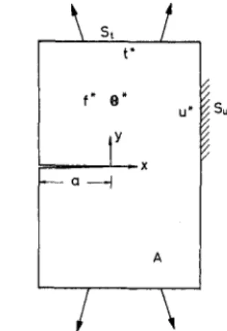
The weight function method as presented by Bueckner (1970) and Rice (1972) was used to compute the mode I stress intensity factor of symmetric cracked bodies with symmetric mechanical loading. Tsai and Ma (1992) extended Rice's displacement de-rivative definition of the weight function formulation for me-chanical loading to mixed fracture mode and mixed boundary conditions of applying mechanical and thermal loadings. Con-sider the geometrical configuration as shown in Fig. 1. There are different sorts of loading type, such as prescribed traction t* at boundary S„ prescribed displacement u* at boundary S„, body force/*, and temperature ®* at domain A. Stress intensity factors are expressed as a product of the applied load and the associated weight function as follows (Ma et al., 1994):
\ s ,
/
r~r
Fig. 1 Configuration of a cracked body subjected to different loading sources
K, = f t*-%dS + \ u*-h?dS + f f*-h{rfA
Js, Js„ JA + \ ®*h\dA (1) J AK
u= \ t*-KdS + I u*-KdS + I f*-h
f„dA
Js, Jsl{ JA+ f ®*h^dA (2)
JAThe different sorts of weight functions are denoted as
2K\ da da J 2K\ 3a da h { =
^ > ^ _ ^
a U < 2 V 2K da da aH („mdoW da$\ IK \ da da /for mode I and
2K \ da da
K
H /„„/dt<2> ..p, dti w IK Kfi ^ J _ _ op da da 2K V da da^^U^f^P™"
2K dada?
dafor mode II, in which
K = K\nKff - ATfW (3) (4) (5) (6) (7) (8) (9) (10) (11) where H = E (Young's modulus) for generalized plane stress and H = El(\ - v2) for plane strain, v being Poisson's ratio.
While a is the coefficient of thermal expansion, akk = CTM +
: ! _ •
1
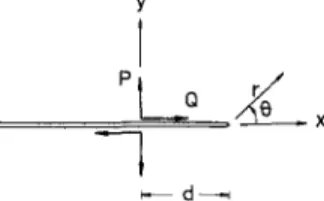
Fig. 2 Configuration of a semi-infinite crack subjected to concentrated force at the crack faces
<Tyy is the sum of normal stresses for two-dimensional problem. The first three terms ((3)-(5)) are known as the traction, dis-placement, and body force mode I weight function, respectively; the last term (Eq. (6)) is known as the thermal mode I weight function. Configurations (1) and (2) are geometrically equiva-lent to the original problem and are subjected to arbitrary load-ings. The corresponding stress intensity factors and displace-ment vectors will be denoted by K{^[h u(1) and K^, u<2), respec-tively. Once the weight functions ((3)—(10)) are determined from particular load systems, the stress intensity factor induced by any other load system can be obtained from Eqs. (1) and (2) by only simple integration. In this paper, only the thermal ing is considered for pure mode I deformation. If thermal load-ing is considered and only induced mode I deformation, then (1) becomes K,
f ®*hl
J A where dA (i) h = 2K\n da (12) (13) Since the derivation of the stress invariant (dakklda) isdiffi-cult to evaluate from the numerical finite element method, (12) and (13) can be reformulated by Green's theorem to an alterna-tive form such that the thermal weight function can be obtained more easily and accurately by the finite element method, which yields
2K\
l)[J \da
y da dxthermal weight function is obtained from the mechanical load-ing applied at the same cracked body.
Before we investigate the thermal weight function of the complicated geometry for hollow cylinder with axial crack, the features of the thermal weight function near the crack tip should be analyzed first. The thermal weight function for a semi-infinite crack is obtained by applying concentrated force at crack faces with distance d from the crack tip, as shown in Fig. 2. The stress field of the problem was solved by using the Westergaard stress function. The stress invariants induced by mode I and mode II deformation are
+ o t „ l l I 11 2 ^ „ / I — Re -7T \Z 2fi Im
z-d,
(15) (16)where the complex variable z stress intensity factors are
Kn =
is x + iy. The corresponding IP '2nd
22
2nd (17) (18) Then from (6) and (10), the thermal weight function of mode I and mode II for the semi-infinite crack can be obtained as follows: H' 2V5TT 3 cos - 1 2K = -
H' 2 ^r3'2
sin - e
2 (19) (20) where H' = aE for plane stress, H' = aEI{\ - v) for plane strain. There are some important characteristics of thermal weight function near the crack tip as indicated in (19) and (20). It shows strong singularity of the order of r~m near the cracktip which is higher than the r~"2 singularity of weight function for mechanical loading. From the mode I thermal weight func-tion hi presented in (19), the equal value lines of the thermal weight function near the crack tip are plotted in Fig. 3. It shows
/ /
<9<5>* duxn <9@* dufxj J
+ — \dxdy
dx da dy da (14)
where H' = E2/(l - v) for plane stress and H' = E2I[(\
-2v){\ — v2)] for plane strain.
Usually, the formulation (12) is more suitable for analytical analysis or for boundary element method to evaluate the thermal weight function, and (14) is especially convenient for the finite element calculation of finite cracked bodies. This expression can also be obtained from the body force analogy method which transfers the thermal loading to mechanical traction and body force.
Since the boundary element method is used in this study, the stress intensity factor induced by thermal loading will be evaluated from (12) and (13). As indicated in (13), the determi-nation of the thermal weight function for the cracked body of interest requires the stress invariant derivative to be established for any arbitrary loading system applied to the same cracked body. Unfortunately, the explicit solution of stress invariant field is available only for very few ideal crack problems. An efficient boundary element method for determining the weight functions for cracked body of interest has been achieved in this study by combining the singular crack-tip elements with the virtual crack extension technique. It should be noted that the
^ 3 o.o
Fig. 3 Thermal weight function of mode I near the crack tip
Fig. 4 The variation of the thermal weight function near the crack tip for different values of y
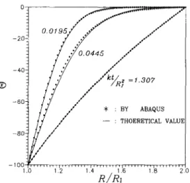
© j =1.307
* : BY ABAQUS — : THOERETICAL VALUE
R/Rl
2.0
Fig. 5 Comparison of the numerical calculation and theoretical evalua-tion of the transient temperature for hollow cylinder
three symmetric patterns and the thermal weight function will be positive only in the region ir/3 s J s -n/3. The thermal weight function for semi-infinite crack as a function of x for different values of y is shown in Fig. 4. It shows that a strong singularity is developed near the crack tip as y is small.
3 Thermal Weight Functions and Transient Stress
Intensity Factors
In order to make sure that the transient temperature evaluated numerically for the hollow cylinder with axial crack is accurate. We consider a hollow cylinder with no crack which has uni-formly distributed temperature 0O initially. At time t = 0, the temperature at the inner wall is suddenly changed to ®i, while the temperature at the outer wall remains as 0O. The radius for inner and outer walls of the hollow cylinder are denoted as R, and R0, respectively. Because of the axial symmetry feature of
this problem, the temperature field will depend only on radial distance R. The transient temperature for this problem is ob-tained by Carslaw and Jaeger (1950); the result is
the calculation must employ the finite element method, which can be time-consuming and expensive for the analysis. The thermal weight function method will be used in this study, which will provide a more efficient methodology in the analyses of thermal shock problems.
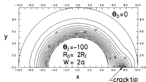
In the analysis of the transient temperature field for a cracked hollow cylinder, the numerical method of finite element is used to construct the solution. We consider first a hollow cylinder with an internal axial crack, subjected to suddenly applied uni-form temperature distribution ©; (= - 1 0 0 ) in the inner wall and ©o (= 0) in the outer wall at time t = 0, as shown in Fig. 6. The temperature in the crack faces is assumed to be the same as that on the internal wall. It is noted that this assumption has been chosen as a good example from a theoretical point of view, and not as a realistic engineering problem. The transient temperature distribution of the cracked hollow cylinder for nor-malized time KtlR\ equal to 0.18 and 1.3 is displayed in Figs. 7 and 8, respectively. For the case of suddenly increasing uni-formly distributed temperature 0O (= 100) in the outer wall, the transient temperature is presented in Figs. 9 and 10.
B = ®o In (R/R,) - ©/ In (R/R0) + y ^ J0(Roan)[URa„)Y0(Rla„) - Y0(Ran)Jo(R^n)] [@MRo<x„)
In (R0/R,) ^ " 4(R,a„) - Jl(Roa„)
®oJo(R,a„)] (21)
where K = D/(pQ, K is the thermal diffusivity, D is the thermal conductivity, p is the density, and C is the specific heat. Eigen-values a„ in (21) are given by solving the root of the equation
J0(R,a)Y0(Roa) - J0(R0a)Yo(R,a) = 0 (22)
where J0 and Y0 are Bessel and Neumann functions of order
zero, respectively. The numerical method (ABAQUS) is used to calculate the transient temperature distribution for 0O = — 100 and ®, = 0. The results for theoretical value (solid lines) evaluated from (22) and numerical result (data points) are both presented in Fig. 5. We can see very good agreement of the theoretical and numerical results shown in this figure.
We would like now to investigate the transient temperature distribution for axial cracks in a hollow cylinder subject to thermal shock. The cracking of brittle material due to thermal shock has been recognized as an important fracture phenomenon in cases such as turbine, combustion chamber or pressure vessel subjected to abnormal operation, or workpieces under the quenching process. Sometimes, the transient thermally induced stress singular behavior is strong enough to fracture the struc-ture. The existing results related to crack subjected to thermal shock are rather limited. This is probably due to the fact that
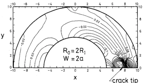
The boundary element method is used to obtain the thermal weight function for the hollow cylinder with an internal axial crack by using (13). The corresponding result is shown in Fig. 11. Then from (12), the transient stress intensity factor can be evaluated by simple numerical integration from the thermal weight function obtained and the transient temperature distribu-tion. The transient stress intensity factors for different crack lengths subjected to sudden temperature drop in the inner wall (©, = -100) are shown in Fig. 12. The stress intensity factor
Fig. 6 Geometry and coordinate definition for hollow cylinder with axial cracks in inner wall
crack tip
Fig. 7 Temperature distribution of a hollow cylinder with an internal axial crack subjected to sudden temperature drop in the inner wall at Kt/Rf = 0.18
-10.0 -8.0 ~1 1 -6.0 -4.0 ~ i — i r i i i r 0 8.0 10.0 -10.0 -8.0 -6.0 -4.0 -2.0 0.0 2.0 4.0 6.0 ^ 8 . 0 10.0
crack tip
Fig. 8 Temperature distribution of a hollow cylinder with an internal axial crack subjected to sudden temperature drop in the inner wall at Kt/Rf = 1.3
-10.0 -8.0 -6.0 -4.0 -2.0 0.0 2.0 4.0 6.0 8.0 10.0
-10.0 -8.0 -6.0 -4.0 -2.0 0.0 2.0 4.0 6.0 JT 8.0 10.0
4:rack tip
Fig. 9 Temperature distribution of a hollow cylinder with an internal axial crack subjected to sudden temperature increase in the outer wall at Kt/Rf = 0049
Fig. 10 Temperature distribution of a hollow cylinder with an internal axial crack subjected to sudden temperature increase in the outer wall at Kt/Rf = 1.49
Fig. 11 The thermal weight function for a hollow cylinder with an internal crack
is normalized with respect to EaA®vW/(l - v), where W = Ro - R: is the wall thickness of the cylinder. There are some
interesting features displayed in this figure. The maximum stress intensity factor in the transient period for short crack (a/W =£ 0.4) is reached before the steady state is established. Hence, the overshot phenomenon of the stress intensity factor is found during the transient period, especially for small cracks. Oliveira and Wu (1987) also investigated a similar problem, but they assumed, for simplicity, the presence of the crack does not affect the temperature distribution. Hence, the transient temperature solution (21) was used for the analysis and the transient stress intensity factors (dashed lines) are shown in Fig. 13. As pre-sented in Fig. 13, a quite different result is obtained if we do not take into account the temperature disturbance by the crack, and an unreasonable result that the stress intensity factor in the steady-state situation for short crack (a/W = 0.3) may be larger than that of the long crack (a/W = 0.5) might be achieved. It is also shown in this figure that the results of the transient stress intensity factors obtained in this study and that in Oliveira and Wu (1987) are quite different, especially in the early period of the transient process. The transient stress intensity factors for different crack lengths subjected to sudden temperature increase in the outer wall ( 0O = 100) are presented in Fig. 14. For this case, the maximum stress intensity factors always occurred in CD < IS LLl I — 4s -o.+o z_
Ro
= 2R, 0.30 -0.20 :w
°
o/W=0.1•
o/W=0.2 A o/W=0.3 0.10 :0
a/W=0.4 0.00 : ft a/W=0.5 0.1kt/Rf
Fig. 12 Transient stress intensity factors of an internal crack for differ-ent crack lengths subjected to sudden temperature drop in the inner wall
BY PRESENT BY [ 1 4 ] O:a/W=0.1 A:a/W=0.3 -&:a/W=0.5 0.0001 0.001 0.01 0.1 1
kt/Rf
Fig. 13 Comparison of the transient stress intensity factors of the inter-nal crack with the case where the temperature distribution is not affected by the crack
fe
0.40 CD < O 0.30 LU\
5 0.20 ^ I £ 0.10 R0 = 2R, Q : a/W=0.2 A : a/W=0.3 0 : a/W=0.4 ft : a/W=0.5 0.00001 0.0001 0.001 0.01 ) 2 0.1 k t / RFig. 15 Transient stress intensity factors of an external crack for differ-ent crack lengths subjected to sudden temperature drop in the outer wall
the steady state, and no overshot will occur in the transient period.
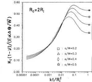
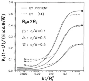
Finally, the transient analysis for a hollow cylinder with an external axial crack subjected to thermal shock is considered. Following a similar procedure as indicated for the internal axial crack, the transient temperature distribution and thermal weight function are constructed. The transient stress intensity factors for different crack lengths subjected to sudden temperature drop in the outer wall (@0 = -100) are shown in Fig. 15. It also shows in this figure that the overshot phenomenon is observed and the magnitude of the overshot is quite large, especially for small cracks. For the case of suddenly increasing temperature in the inner wall (©; = 100), the transient stress intensity factors for different crack lengths are shown in Fig. 16. It shows no overshot will be present in this case. Figure 17 (dashed lines) shows the results obtained by Oliveira and Wu (1987) by using the analytical transient temperature distribution (21) are in very good agreement with the results obtained in this study for this particular case.
4 Conclusions
The evaluation of the stress intensity factor by means of the weight function method is more favorable than that of the finite
element method because of the load independence characteris-tics of weight functions. The key advantage of the thermal weight function method is that once the thermal weight function is predetermined for a given crack geometry, accurate stress intensity factors for any other loading conditions for the same crack geometry can be obtained by a simple integration. There-fore, the use of the thermal weight function concept can obviate the need for repeated computer computations of transient stress intensity factors for a given crack geometry subjected to thermal shock conditions.
In this study, the efficient thermal weight function method is used to calculate the stress intensity factors for a hollow cylinder with an axial crack subjected to thermal loadings. The weight function concept for mechanical loading is now a common method to determine the stress intensity factor. However, the thermal weight function concept is not widely used yet, and it is proved in this study that the method is more convenient and efficient than other methods used in the literature. If the temperature distribution is known, then the stress intensity fac-tor of a cracked body can be obtained by a simple integration over the predetermined thermal weight function.
There are some important results obtained in this analysis. We find that the maximum stress intensity factor may occur during the transient period and the overshot will be present,
•6 LU 0.30 «-N 0.20 Ro
= 2R,
: O a/W=0.1 1 o a/W=0.2 : A a/W=0.3; o
a/W=0.4 ; ft a/W=0.5 i i I I I N I i I i i mil 1—r I m i l l r— '! ' 1 ll'IM} 0.0001 0.001 0.01 0.1 1kt/Rf
Ro=2R 0.0001 0.001 k t / R ,2Fig. 14 Transient stress intensity factors of an internal crack for Fig. 16 Transient stress intensity factors of an external crack for differ-ent crack lengths subjected to sudden temperature increase in the outer differ-ent crack lengths subjected to sudden temperature increase in the inner wall wall
<
LU : * : 0.1 -. BY PRESENT 0.0 1 I M l l l l l 0.0001 0.001 0.01 0.1kt/R,
2Fig. 17 Comparison of the transient stress intensity factors of the exter-nal crack with the case where the temperature distribution is not affected by the crack
especially for small cracks. Hence, the steady-state analysis may
not be adequate for the investigation of cracked body subjected
to thermal shock. To analyze the problem for cracked body
subjected to thermal shock accurately, the disturbance of the
transient temperature distribution by the crack should be taken
into account. The existence of the crack will influence the
tem-perature field near the crack, and one will obtain very different
results for evaluating the stress intensity factor from those that
do not take the crack into account.
Acknowledgments
The financial support by the National Science Council
(Re-public of China) through Grant No. NSC78-0210-D002-19 and
by Atomic Energy Council are gratefully acknowledged.
References
Bahr, H.-A., and Balke, H., 1987, "Fracture Analysis of a Single Edge Cracked Strip under Thermal Shock," Theoretical and Applied Fracture Mechanics, Vol. 8, pp. 33-39.
Bueckner, H. F„ 1970, "A Novel Principle for the Computation of Stress Intensity Factors," ZAMM, Vol. 50, pp. 529-546.
Carslaw, H. S., and Jaeger, J. C , 1950, Conduction of Heat in Solids, Oxford University Press, Oxford, U.K.
Emery, A. F., Walker, G. E„ and Williams, J. A., 1969, " A Green Function for the Stress Intensity Factors of Edge Cracks and Its Application to Thermal Stress," ASME Journal of Applied Mechanics, Vol. 36, pp. 618-624.
Florence, A. L., and Goodier, J. N., 1960, "Thermal Stresses Due to Distur-bance of Uniform Heat Flow by an Insulated Ovaloid Hole," ASME Journal of Applied Mechanics, Vol. 27, pp. 635-639.
Florence, A. L., and Goodier, J. N., 1963, "The Linearly Thermoelastic Prob-lem of Uniform Heat Flow Disturbed by a Penny-Shaped Crack," International Journal of Engineering Science, Vol. 1, pp. 533-540.
Gregory, R. D., 1977, "A Circular Disc Containing a Radial Edge Crack Opened by a Constant Internal Pressure," Mathematical Procedures of Camb. Philosophical Society, Vol. 81, pp. 497-521.
Gregory, R. D., 1979, "The Edge-Cracked Circular Disc under Symmetric Pin-Loading," Mathematical Procedures of Camb. Philosophical Society, Vol. 85, pp. 523-538.
Gregory, R. D., 1989, "The Spinning Circular Disc with a Radial Edge Crack: An Exact Solution," International Journal of Fracture, Vol. 41, pp. 39-50.
Hellen, T. K., 1975, "On the Method of Virtual Crack Extensions," Interna-tional Journal of Numerical Methods in Engineering, Vol. 9, pp. 187-207.
Hellen, T. K„ and Cesari, F., 1979, "On the Solution of the Center Cracked Plate with a Quadratic Thermal Gradient," Engineering Fracture Mechanics, Vol. 12, pp. 469-478.
Kassir, M. K., and Sih, G. C , 1968, "Thermal Stress in a Solid Weakened by an External Circular Crack," International Journal of Solids and Structures, Vol. 5, pp. 351-367.
Kassir, M. K., and Bregman, A. M„ 1971, "Thermal Stress in a Solid Containing Parallel Circular Crack," Applied Scientific Research, Vol. 25, pp. 2 6 2 -280.
Ma, C. C , Chang, Z„ and Tsai, C. H„ 1990, "Weight Functions of Oblique Edge and Center Cracks in Finite Bodies," Engineering Fracture Mechanics, Vol. 36, pp. 267-285.
Ma, C. C , Huang, J. I., and Tsai, C. H„ 1994, "Weight Functions and Stress Intensity Factors for Axial Cracks in Hollow Cylinders," ASME JOURNAL OF
PRESSURE VESSEL TECHNOLOGY, Vol. 116, pp. 423-430.
Nied, H. F„ 1983, "Thermal Shock Fracture in an Edge-Cracked Plate," Jour-nal of Thermal Stress, Vol. 6, pp. 217-229.
Olesiak, Z., and Sneddon, I. N., 1959, "The Distribution of Thermal Stress in an Infinite Elastic Solid Containing a Penny-Shaped Crack," Archives of Rational Mechanics Analysis, Vol. 4, pp. 238-254.
Oliveira, R., and Wu, X. R„ 1987, "Stress Intensity Factor for Axial Cracks in Hollow Cylinders Subjected to Thermal Shock," Engineering Fracture Me-chanics, Vol. 27, pp. 185-197.
Parks, D. M., 1974, " A Stiffness Derivative Finite Element Technique for Determination of Crack Tip Stress Intensity Factors," International Journal of Fracture, Vol. 10, pp. 487-501.
Rice, J. R., 1972, "Some Remarks on Elastic Crack-Tip Stress Field," Interna-tional Journal of Solids and Structures, Vol. 8, pp. 751-758.
Rooke, D. P., and Cartwright, D. J., 1976, Compendium of Stress Intensity Factors, Her Majesty's Stationery Office, London, U.K.
Saillard, P., Devaux, J. C , and Pellissier-Tanon, A., 1987, "Numerical Predic-tion of the Fracture of a Thick Pressurized Shell Subjected to a Liquid Nitrogen Shock," Nuclear Engineering and Design, Vol. 105, pp. 83-88.
Sha, G. T., 1984, "Stiffness Derivative Finite Element Technique to Determine Nodal Weight Functions with Singularity Elements," Engineering Fracture Me-chanics, Vol. 19, pp. 685-699.
Sha, G. T., and Yang, C. T., 1985, "Weight Function Calculations for Mixed-Mode. Fracture Problems with the Virtual Crack Extension Technique," Engi-neering Fracture Mechanics, Vol. 21, pp. 1119-1149.
Sih, G. C , 1962, "On the Singular Character of Thermal Stress Near a Crack Tip," ASME Journal of Applied Mechanics, Vol. 29, pp. 587-589.
Sih, G. C , 1973, Handbook of Stress Intensity Factors, Institute of Fracture and Solid Mechanics, Lehigh University, PA.
Tada, H„ Paris, P. C , and Irwin, G. R., 1973, The Stress Analysis of Cracks Handbook, Del Research Corporation, Hellertown, PA.
Tsai, C. H., and Ma, C. C , 1989, "Weight Functions for Cracks in Finite Rectangular Plates," International Journal of Fracture, Vol. 40, pp. 4 3 - 6 3 .
Tsai, C. H., and Ma, C. C , 1992, "Thermal Weight Function of Cracked Bodies Subjected to Thermal Loading," Engineering Fracture Mechanics, Vol. 41, pp. 27-40.
Wilson, W. K., and Yu, I. W„ 1979, "The Use of the /-Integral in Thermal Stress Crack Problems," International Journal of Fracture, Vol. 15, pp. 3 7 7 -387.
Wu, X. R., 1991, "The Arbitrarily Loaded Single-Edge Cracked Circular Disc Accurate Weight Function Solutions," International Journal of Fracture, Vol. 49, pp. 239-256.