一個非同步低耦合度之動態格網運算系統
93
0
0
全文
(2) 一個非同步低耦合度之動態格網運算系統 An Asynchronous Decoupled Dynamic Grid Computation System. 研 究 生:沈上謙. Student:Shang-chien Shen. 指導教授:袁賢銘. Advisor:Shyan-ming Yuan. 國 立 交 通 大 學 資 訊 科 學 系 碩 士 論 文. A Thesis Submitted to Department of Computer and Information Science College of Electrical Engineering and Computer Science National Chiao Tung University in partial Fulfillment of the Requirements for the Degree of Master in Computer and Information Science June 2005 Hsinchu, Taiwan, Republic of China. 中華民國九十四年六月 ii.
(3) 一個非同步低耦合度之動態格網運算系統. 研究生:沈上謙. 指導教授:袁賢銘. 國立交通大學電機資訊學院 資訊科學研究所. 摘要. 諸如基因排序以及蛋白質解析等複雜的解碼工作需要大量的運算量以及繁複眾 多的執行步驟,業界多半利用格網運算(Grid Computing)的方式將繁重的運算工 作交予後端的分散式叢集電腦群來快速完成,這一類的格網系統通常仰賴著昂貴 的硬體設備或是特殊、特定的軟體,使得格網運算這個名詞數年以來一直狹隘地 隸屬於高速科學計算的領域。縱使在科學領域已被廣泛使用,昂貴的整體擁有成 本(Total Cost of Ownership)讓一般使用者或甚至中小型企業對於採用格網概念 望之卻步。龐大的潛在電腦運算資源依然未能有效被利用。使用者持續尋找著更 多的運算資源來解決他們的問題。在這些挑戰之上,格網本身尚暴露著技術層面 的瑕疵。業界的方案無法有效解決諸如此類單一切入點故障(Single-point of Failure)的架構性問題、動態擴充格網體積的延展性問題(Scalability)、或是支援 跨平台特性的普及性問題。 本篇論文提出一個低成本的純軟體跨平台格網方案,有效解決單一切入點故障、 動態擴充格網體積等問題,並提供簡化格網應用程式開發的工具組以及程式設計 介面(API),大幅縮短研發人員粹取企業內部運算資源的時間,將生產力最佳化。 研發人員將能專注於設計與開發,而不再需要週而復始地在企業中辛苦獵取閒置 但是隱形的運算資源。. iii.
(4) An Asynchronous Decoupled Dynamic Grid Computation System. Student:Shang-chien Shen. Advisor:Dr. Shyan-ming Yuan. Department of Computer and Information Science College of Electrical Engineering and Computer Science National Chiao Tung University. Abstract. Complex jobs such as bio-genetic sequencing and protein modeling requires massive quantity of calculation and execution procedures. Today, industry applies Grid Computing technologies to delegate the intensive computational work to a farm of cluster computers in order to accelerate computing speed. This category of grid computing rely on sumptuous hardware or distinctive, specific software, thus restraining grid computing to constricted domains such as high-speed scientific computation. Despite the widespread acceptance of grid concept, high TCO(Total Cost of Ownership) intimidated the general public or even SMEs(Small-Medium Enterprises) from adopting grid technologies. Vast amount of potential computing capacity still remains untapped. Users are continually searching for more computing resources to assist solve problems. On top of these challenges, Grid itself suffers certain technical imperfections. Commercial solutions are incapable of solving single-point-of-failure issues, incapable of dynamically expanding the volume of grid network and is certainly having a difficult time migrating grid infrastructure to a universe of different electronic devices existing today.. iv.
(5) This research proposes a low-cost, pure software-based, cross-platform grid framework, eliminating the mishap of single-point of failure, allowing dynamic grid expansion. The framework also provides utility tools and Application Programming Interfaces(APIs) that simplifies the process of grid application development, thus optimizes overall productivity. Developers must focus on design and development rather than hunting for resources hidden within the enterprise.. v.
(6) Acknowledgement 首先我要感謝在這兩年的歷程之中給予我珍貴的建議,並引導我朝正確研究方向 邁進的指導教授 袁賢銘 教授,在指導過程之中給予我龐大的空間讓我自由揮灑 創意。另外要感謝 蕭存喻、高子漢、葉秉哲 與 吳瑞祥 四位學長不時給我豐富 的意見以及適時的鼓勵讓我可以順利地完成這篇論文。同時也謝謝分散式系統實 驗室裡的成員 柯憲昌、葉倫武、顏志明,在研究上彼此互助交換意見,相互學 習,一起成長。特別謝謝 憲昌在計畫中幫了我許許多多的忙,祝福他進入產業 界後能順利將自己心中的理想與憧憬實現。 最後,謹將此篇小小的學術成就獻給我的父母親 沈立勝 與 王麗文 ,感謝你們 給予我良好的環境讓我求學生涯無後顧之憂,專心於學術研究,同時也謝謝你們 多年以來對我無條件地支持與栽培。. vi.
(7) TABLE OF CONTENTS ACKNOWLEDGEMENT .................................................................................................................. VI TABLE OF CONTENTS ...................................................................................................................VII LIST OF FIGURES............................................................................................................................... X LIST OF TABLES ..............................................................................................................................XII LIST OF CODES.............................................................................................................................. XIII 1. INTRODUCTION ............................................................................................................................1 1.1. PREFACE...................................................................................................................................1 1.2. MOTIVATION .............................................................................................................................1 1.3. RESEARCH OBJECTIVES .....................................................................................................2 1.3.1 Low-Cost and Cross-Platform...............................................................................................3 1.3.2 High Performance Resource Sharing ..................................................................................3 1.3.3 High-Scalability ....................................................................................................................4 1.3.4 High-Flexibility.....................................................................................................................4 1.3.5 Simple-to-Use ........................................................................................................................4 1.4. RESEARCH CONTRIBUTION ................................................................................................5 1.5. OUTLINE OF THE THESIS......................................................................................................6 1.6. SUMMARY .................................................................................................................................7 2. BACKGROUND .............................................................................................................................8 2.1. CHAPTER INTRODUCTION ...................................................................................................8 2.2. SUPER COMPUTER, PHYSICAL CLUSTER AND VIRTUAL GRID.................................9 2.3. GRID COMPUTING DEFINITION .........................................................................................10 2.4. SYSTEM ARCHITECTURES.................................................................................................12 2.4.1 Client-Server Architecture ..................................................................................................12 2.4.2 Peer-to-Peer Architecture....................................................................................................13 2.4.3 Space-oriented Architecture................................................................................................14 2.5. COMMUNICATION MODELS ...............................................................................................15 2.5.1 Synchronous Transmission Model .....................................................................................15 2.5.2 Asynchronous Transmission Model....................................................................................16 2.6. RELATED WORKS .................................................................................................................17 2.7. SUMMARY ...............................................................................................................................18 3. SYSTEM ARCHITECTURE........................................................................................................19 3.1. OVERVIEW ..............................................................................................................................19 3.2. MGRID PLATFORM..................................................................................................................20. vii.
(8) 3.2.1 HTTP Server........................................................................................................................22 3.2.2 Activation Daemon..............................................................................................................22 3.2.3 Nucleus Service ...................................................................................................................24 3.2.4 Distributed Space Service ...................................................................................................26 3.2.5 Transaction Service.............................................................................................................29 3.2.6 Leasing Service ...................................................................................................................31 3.2.7 Security Service ...................................................................................................................32 3.2.8 GC Service (Garbage-Collector Service) ............................................................................32 3.3. MGRID ENGINE ........................................................................................................................33 3.3.1 Engine Kernel .....................................................................................................................34 3.3.2 Generic Task Processor (GTP)............................................................................................36 3.3.3 JVM Monitor.......................................................................................................................38 3.3.4 Machine Monitor ................................................................................................................38 3.3.5 Engine Command Listener .................................................................................................38 3.4. MGRID TOOLKIT ......................................................................................................................39 3.4.1 Engines Monitor .................................................................................................................42 3.4.2 Command Issuer .................................................................................................................42 3.4.3 GUI Displayer .....................................................................................................................43 3.5. SYSTEM NON-FUNCTIONAL ISSUES: SCALABILITY AND FLEXIBILITY.................43 3.6. SUMMARY ...............................................................................................................................44 4. PROGRAMMING INTERFACE DESIGN..................................................................................45 4.1. FOREWORD ............................................................................................................................45 4.2. MGRID.API PACKAGE..............................................................................................................46 4.3. MGRID.ENGINE PACKAGE.......................................................................................................52 4.4. MGRID.TOOLKIT PACKAGE .....................................................................................................54 4.5. MGRID.EXAMPLES PACKAGE .................................................................................................56 4.6. RECOMMENDED MGRID APPLICATIONS .........................................................................56 4.7. SUMMARY ...............................................................................................................................57 5. EXPERIMENT AND EVALUATION...........................................................................................58 5.1. LINPACK BENCHMARK .......................................................................................................58 5.2. COMPARISON WITH MULTI-PROCESSOR MACHINES ................................................59 5.2.1 Performance: Multiprocessor vs. mGrid ............................................................................59 5.2.2 Utilization: Multiprocessor vs. mGrid ................................................................................60 5.2.3 Scalability: Multiprocessor vs. mGrid ................................................................................62 5.2.4 More on Performance: The number of Spaces matters .....................................................62 5.3. COMPARISON WITH CLUSTERS .......................................................................................63 5.3.1 Performance: Clusters vs. mGrid .......................................................................................63 viii.
(9) 5.3.2 Total Cost of Ownership: Clusters vs. mGrid .....................................................................64 5.3.3 Single-Point-of-Failure Issue: Clusters vs. mGrid ............................................................66 5.4. DISCUSSION...........................................................................................................................66 6. CONCLUSION, BUSINESS OPPORTUNITIES & FUTURE WORKS ................................69 6.1. CONCLUSION & BUSINESS OPPORTUNITIES...............................................................69 6.2. FUTURE WORKS ...................................................................................................................70 REFERENCES.....................................................................................................................................72 APPENDIX: USER TUTORIAL ......................................................................................................75 ▪ RECOMMENDED DEVELOPMENT FLOW .............................................................................75 ▪ MGRID PLATFORM QUICK SETUP ...........................................................................................76 ▪ MGRID ENGINE QUICK GUIDE ..................................................................................................76 ▪ MGRID TOOLKIT QUICK GUIDE ................................................................................................78 ▪ RUNNING AN EXAMPLE............................................................................................................79. ix.
(10) LIST OF FIGURES FIGURE 1-1: MGRID PLATFORM RUNS ON VARIOUS ELECTRONIC DEVICES WITH JAVA SUPPORT ...........5 FIGURE 2-1: A CLIENT-SERVER BASED GRID ARCHITECTURE[16].........................................................12 FIGURE 2-2: A PEER-TP-PEER BASED GRID ARCHITECTURE[16] ..........................................................13 FIGURE 2-3: A SPCAE-ORIENTED GRID ARCHITECTURE ........................................................................14 FIGURE 3-1: MACROSCOPIC VIEW OF MGRID FRAMEWORK. MGRID IS CONSISTED OF FOUR MAJOR PORTIONS ......................................................................................................................................19. FIGURE 3-2: IN-DEPTH COMPONENT VIEW OF THE MGRID PLATFORM, INDICATED IN RED ...................21 FIGURE 3-3: UNDERLYING CODE TRANSMISSION STEPS FOR MGRID PLATFORM ..................................23 FIGURE 3-4: HOW NUCLEUS SERVICE WORKS WITH THE OTHER SERVICES FROM MGRID PLATFORM .25 FIGURE 3-5: ALL SERVICE COMPONENTS NEEDS TO REGISTER WITH THE NUCLEUS SERVICE UPON START ............................................................................................................................................26. FIGURE 3-6: THE SPCAE-ORIENTED GRID ARCHITECTURE USED IN MGRID FRAMEWORK ...................27 FIGURE 3-7: A SPACE IS CONSISTED OF SEVERAL COMPUTING DEVICES ..............................................28 FIGURE 3-8: TRANSACTION SERVICE SUPPORTS THE 2-PHASE COMMIT PROTOCOL: EITHER ALL OR NONE! ............................................................................................................................................30. FIGURE 3-9: IN-DEPTH COMPONENT VIEW OF THE MGRID ENGINE, INDICATED IN RED ........................33 FIGURE 3-10: ENGINE KERNEL CONSTANTLY FETCH TASKS FROM SPACE.............................................35 FIGURE 3-11: IN-DEPTH COMPONENT VIEW OF THE MGRID TOOLKIT, INDICATED IN RED .....................39 FIGURE 3-12: MGRID TOOLKIT AND ENGINE INITIAL LINKING STEPS - WHEN THE TOOLKIT RESIDES IN WAN .............................................................................................................................................40 FIGURE 3-13: WHEN THE TOOLKIT RESIDES IN LAN, THE ALGORITHM NEEDS TO BE SLIGHTLY MODIFIED ......................................................................................................................................................41 FIGURE 4-1: HIGH-LEVEL VIEW OF THE ENTIRE MGRID API LIBRARY, INDICATED IN RED .....................45 FIGURE 4-2: UML CLASS DIAGRAM OF MGRID.API. SIMPLICITY IS OUR PRIMARY OBJECTIVE ..............47 FIGURE 4-3: UML CLASS DIAGRAM OF CPUUSAGE UTILITY CLASS WITHIN MGRID.ENGINE PACKAGE .52 FIGURE 4-4: UML CLASS DIAGRAM OF MONITORINGTHREAD UTILITY CLASS WITHIN MGRID.TOOLKIT PACKAGE .......................................................................................................................................54. FIGURE 5-1: OUR TEST CASE. AX=B WHERE K=1000...........................................................................58 FIGURE 5-2: PERFORMANCE COMPARISON WITH MULTIPROCESSOR MACHINES, CHART VIEW ............60 FIGURE 5-3: PERFORMANCE & TCO COMPARISON WITH CLUSTERSS, MGRID IS MUCH COST-EFFECTIVE!..........................................................................................................................65. FIGURE 5-4: OVERALL COMPARISON BETWEEN MGRID, MULTIPROCESSOR & GRIDS/CLUSTERS ........67 FIGURE APPENDIX-1: RECOMMENDED MGRID FRAMEWORK DEVELOPMENT FLOW .............................75 FIGURE APPENDIX-2: THE BATCH FILES THAT STARTS THE MGRID PLATFORM, SIMPLE AND STRAIGHT-FORWARD .....................................................................................................................76. FIGURE APPENDIX-3: MGRID ENGINE GRAPHICAL USER INTERFACE ....................................................77 FIGURE APPENDIX-4: MGRID TOOLKIT LOGIN SCREEN ..........................................................................78 x.
(11) FIGURE APPENDIX-5: MGRID TOOLKIT MAIN INTERFACE. CLEAR VIEW OF A COMPLICATED GRID NETWORK! .....................................................................................................................................79. FIGURE APPENDIX-6: 3D ROTATING DEMO PROGRAM. THE MORE MGRID ENGINES, THE FASTER IT ROTATES!.......................................................................................................................................80. xi.
(12) LIST OF TABLES TABLE 1-1: COST OF UNUSED COMPUTATIONAL RESOURCES [1] ............................................................1 TABLE 2-1: COMPARISON OF SUPER COMPUTERS, CLUSTERS AND GRIDS [10][11][12][13] ..................9 TABLE 5-1: PERFORMANCE COMPARISON WITH COMMERCIAL MULTIPROCESSOR MACHINES (MFLOP/S) ......................................................................................................................................................60 TABLE 5-2: CPU RESOURCE WASTED (%)............................................................................................61 TABLE 5-3: CPU RESOURCE UTILIZATION COMPARISON BETWEEN MULTIPROCESSOR PRODUCTS AND MGRID ...........................................................................................................................................61. TABLE 5-4: MGRID SYSTEM SCALES EASILY (MFLOP/S)........................................................................62 TABLE 5-5: PERFORMANCE COMPARISON WITH COMMERCIAL CLUSTERS ............................................64 TABLE 5-6: TCO(TOTAL COST OF OWNERSHIP) COMPARISON OF MGRID WITH COMMERCIAL CLUSTERS[28]...............................................................................................................................65. TABLE 5-7: SITUATION CONSIDERING THE NUMBER OF SPACES FAILED (MFLOP/S)..............................66 TABLE 5-8: SUPPOSE WE COMBINE FOUR CPUS TOGETHER INTO A MGRID VIRTUAL GRID, WHAT DO WE GET?..............................................................................................................................................67. xii.
(13) LIST OF CODES LISTING 3-1: TRANSACTION ALGORITHM PSEUDO-CODE .......................................................................31 LISTING 3-2: POLICY FILE THAT ALLOWS TOTAL ACCESS TO MGRID PLATFORM FROM ANYONE. ..........32 LISTING 3-3: ALLOWS TOTAL ACCESS EXCEPT FOR INCOMING CONNECTION FROM IP 192.168.11.2 ..32 LISTING 3-4: A NAÏVE GTP IMPLEMENTATION PSEUDO-CODE ...............................................................36 LISTING 3-5: A MODIFIED GTP IMPLEMENTATION PSEUDO-CODE – BETTER SOLUTION ........................37 LISTING 4-1: A SIMPLE EXAMPLE OF UTILIZING SPACEACCESSOR, TASKENTRY AND RESULTENTRY ..48 LISTING 4-2: EXAMPLE CLASS EXTENDINGTASKENTRY.........................................................................49 LISTING 4-3: EXAMPLE CLASS EXTENDING RESULTENTRY ...................................................................49 LISTING 4-4: EXAMPLE CODE THAT FETCHES A REMOTE ENGINE’S INFO AND DISPLAYS ITS CONTENTS ......................................................................................................................................................50 LISTING 4-5: EXAMPLE CODE THAT SENDS A SHUTDOWN COMMAND TO A REMOTE ENGINE .................51 LISTING 4-6: AN EXAMPLE CODE SEGMENT USING THE CPUUSAGE CLASS ..........................................53 LISTING 4-7: EXAMPLE CODE THAT USES MONITORINGTHREAD CLASS TO DISPLAY ALL ENGINES ON NETWORK ......................................................................................................................................55. xiii.
(14) 1.. INTRODUCTION. 1.1. PREFACE Complex jobs such as bio-genetic sequencing and protein modeling requires massive quantity of calculation and execution procedures. Today, industry applies Grid Computing technologies to delegate the intensive computational work to a farm of cluster computers in order to accelerate computing speed. This category of grid computing rely on sumptuous hardware or distinctive, specific software, thus restraining grid computing to constricted domains such as high-speed scientific computation.. 1.2. MOTIVATION Despite the widespread acceptance of grid concept, high TCO (Total Cost of Ownership) intimidated the general public or even SMEs(Small-Medium Enterprises) from adopting grid technologies. Vast amount of potential computing capacity still remains untapped. Table 1-1[1] designates a research adapted from Internet Infrastructure & Services by Bear, Stearns & Co., quantifying the total idle computational resources, into a more tangible measurement. The result is astonishing.. $/processor. $/used. $/used processor Cost of unused cycles. 1 desktop. $1,200. $300. $150. $1,050. 1000 desktops. $1,200,000. $300,000. $150,000. $1,050,000. Table 1-1: Cost of unused computational resources [1]. 1.
(15) According to the research, an enterprise with one thousand computers wastes minimum of $1.05 million worth of computational resources daily. On top of things, Grid itself still suffers certain technical imperfections. Commercial solutions such as the SUN Grid [2] are incapable of solving single-point-of-failure issues, incapable of dynamically expanding the volume of grid network and is certainly having a difficult time migrating grid infrastructure to a universe of different electronic devices existing today. In addition, the steep learning curve substantially increases the cost and risk of developing a stable real-world grid application. We must keep in mind that grid users are seldom experts in distributed technology, the significance of their innovation in developing applications often exceeds their knowledge towards grids. Thus, middleware providers need to provide exception-free, thread-safe and simple-to-use tools and APIs for grid application developers. This research proposes a low-cost, pure software-based, cross-platform grid framework, named mGrid. mGrid eliminates the mishap of single-point of failure and permits dynamic grid expansion. The framework also provides utility tools and Application Programming Interfaces(APIs) that simplifies the process of grid application development, thus optimizes overall productivity. Developers must focus on design and development rather than hunting for resources hidden within the enterprise.. 1.3. RESEARCH OBJECTIVES mGrid framework is intended to achieve six major objectives: low-cost, cross-platform, high performance resource sharing, high-scalability, high-flexibility. 2.
(16) and simple-to-use.. 1.3.1 Low-Cost and Cross-Platform Sumptuous hardware or distinctive, specific software is a key problem averting grid technologies from being embraced by the general public. In order for grid solutions to be extensively adopted, two issues needs to be taken into consideration. First is the cost issue, the TCO of owning a grid must be sufficiently acceptable. The second is the ability to connect various electronic devices existing today. In other words, the cross-platform characteristic of a grid solution directly determines the potential volume of the grid in the future.. 1.3.2 High Performance Resource Sharing Performance is undeniably the key measurement in evaluating a grid middleware. People expect grids to be fast, reliable and stable, anything less would be intolerable. Performance in grid systems is effected by two sets of elements: ● The nature of the job submitted to the grid. Sequential computation is by nature the worst case in grid performance, compared to complete parallel computations. ● Grid architecture design. Bad task scheduling algorithms could lead to potential bottleneck of the whole system, while naive control-message routing strategy could quickly overload the grid environment. From the middleware provider’s point of view, the first element is beyond our scope. Nevertheless, the second element is the responsibility of a good grid middleware.. 3.
(17) 1.3.3 High-Scalability The performance growth of a grid is direct proportional to how fast it can scale, e.g. the more computers that is currently within/joining the grid, the faster it processes tasks. Scalability can be classified into two categories: static and dynamic. Majority of commercial grids supports only static scaling, the grid size is fixed to a predefined cluster of computers, new computers joining the grid will require manual modification of attributes in the central task dispatching server. Dynamic scaling does not require manual interference, new computers notifies the grid of its existence automatically. Grid systems should be able to scale dynamically and scale high.. 1.3.4 High-Flexibility A grid framework should preserve resilience for application developers. Grid computing is an approach that lets you organize widespread, diverse collections of resources into a more uniform, manageable, visual whole. The resources we are referring here does not narrowly limit to CPU or storage, it might refer to anything with digital representation, e.g. Multimedia files, libraries, data, applications…etc. A good grid middleware should be as flexible as possible, it should not confine the innovation of grid application programmers within the scope of a badly designed middleware API. In other words, creativity should not be limited by the framework.. 1.3.5 Simple-to-Use Grid systems involves complicated low-level network communications and protocol design. A grid middleware has the responsibility to hide these underlying complexities.. 4.
(18) A set of simple-to-use Application Programmer Interfaces(APIs) should be provided for application designers. Furthermore, cumbersome grid administrative jobs should be made simple by utility tools, provided with the middleware.. 1.4. RESEARCH CONTRIBUTION To achieve the objectives listed in section 1.3, we encountered various perplexities while designing mGrid. This thesis discusses the issues that were encountered and our corresponding solutions. The major contributions of this research can thus be categorized into seven parts. ● We crafted a low-cost, pure software-based high performance grid solution that works on various devices with java support. Figure 1-1 below depicts this cross-platform characteristic:. Figure 1-1: mGrid platform runs on various electronic devices with Java support 5.
(19) ● We introduced a simple-to-use grid programming model. ● We introduced a set of utility tools to facilitate the administration of mGrid. ● We discussed the scalability issues in grid middleware, and implemented mGrid with a decentralized space-oriented architecture that supports dynamic grid expansion, and effectively solved the single-point-of-failure problem. ● We discussed the flexibility issues of grid middleware and proposed a considerably general platform for developers to write a variety of grid applications. ● We experimented mGrid performance with a modified version of the Linpack benchmark[3], a standard benchmarking program for commercial super computers. ● We analyzed the pros and cons of various grid design decisions.. 1.5. OUTLINE OF THE THESIS This dissertation is composed of six chapters. Chapter 1, this one, is introductory. In Chapter 2, we introduce the background of grid computing methodologies and bring forth major commercial solutions for discussion. In Chapter 3, we confer the detail implementations of mGrid framework. This section proposes our peculiar distributed algorithms and system architectures that render life to mGrid, pro and con of various design decisions is also debated here. In Chapter 4, we switch to the developers’ point of view by introducing the mGrid API. We can appreciate the ease in both writing grid applications and administrating grid environments using tools and APIs supplied with mGrid. This chapter also serves as a tutorial for the developers to operate the mGrid framework. Last but not least,. 6.
(20) some innovative example applications of mGrid framework is also presented here. In Chapter 5, we put mGrid performance to the test using a modified version of Linpack benchmark[3]. Various experiments will be held and the performance of mGrid framework will be thoroughly quantified. Finally, in Chapter 6, we bring forth conclusion and a brief discussion on future works along with potential business opportunities.. 1.6. SUMMARY In this chapter we briefly described what grid computing is, what it can do, and the problems that exists with industrial grid solutions today. Grids are expensive thus intimidated the general public or SMEs(Small-Medium Enterprises) from adopting grid technologies. Furthermore, commercial grids still suffer from technical imperfections. Then we pointed out the objectives of this thesis and introduced our proposed grid system, named mGrid framework. In the end we categorized the major contributions of this research into multiple points.. 7.
(21) 2.. BACKGROUND. 2.1. CHAPTER INTRODUCTION This chapter gives you the background of our research. To begin with, in section 2.2, we bring forth an interesting comparison of three popular models of super computing, namely super computers, physical clusters and virtual grids. A survey on their price, capability, size and such is revealed here. This survey serve as one of our basis in explaining why grid concept is gradually replacing traditional super computers or large mainframe clusters. Next, we introduce the definition of grid computing according to TurboWrox Corporation[9] in section 2.3. What is a grid? How can it be applied? What applications are suitable to be submitted to a grid for processing? What are not? It is known that commercial grid solutions are implemented using dissimilar architectures and communication models, which possesses different characteristics. Sections 2.4 and 2.5 discusses several approaches in implementing a grid, the pros and cons, and explain why we choose a particular model. Finally we introduce other related works in section 2.6. Note that each survey we made has a certain level of impact on how we implement the mGrid Framework. We try to present to you concrete evidence referenced from other academic researches and industrial studies to justify our path of choice.. 8.
(22) 2.2. SUPER COMPUTER, PHYSICAL CLUSTER AND VIRTUAL GRID Grid computing is not the only option in efficiently solving complicated scientific calculations, there are other options existing. These options includes: ● Super Computers. Large and expensive singular computing hardware, normally used in areas such as weather condition modeling and nuclear simulation. Famous examples include NEC Earth simulator[10] and IBM ASCI White[11]. ● Physical Clusters. Supercomputing devices consists of a large number of computers. Each of the computing node is interconnected using a LAN. Physical clusters usually resides within a single organization and is rarely open to the public. Jobs are dispatched to the back-end cluster for computation. ● Virtual Grids. PCs’ computing capacity are donated freely to join virtual grids. Each PC is connected across the internet using software programs. Famous examples include SETI@Home[12], Folding@Home[13] and GIMPS[14]. A virtual grid usually span across several geographical locations. These three options possesses different characteristics. Entry barriers in adopting each of the mentioned technology is also different. Table 2-1 presents a comparison of these three choices, using commercial products as example:. Computing Option. Name. Specification. Cost (million USD). Super Computer. IBM ASCI White. 8192 RS/6000 processors. $110. 6TB memory Super Computer. NEC Earth Sim. 5104 vector processors. $350. 16GB memory Physical Cluster. 100,000 Intel P4 1G processors $213 256MB memory. Virtual Grid. 100,000 Intel P4 1G. Absorbed by PC owners. 256MB memory. Table 2-1: Comparison of super computers, clusters and grids [10][11][12][13] 9.
(23) According to a market research report by the Insight Research Corporation in 2004, cost is the primary decisive factor for the adoption of super computing devices[15]. This means, the higher the TCO(Total Cost of Ownership) for an enterprise to obtain a grid, the lower chance that they will actually adopt the technology. Table 2-1 shows that virtual grids proliferated an undeniable attraction due to its low-cost. Therefore, one of our major research objective is in creating a low-cost grid framework that provide all the necessary functions of a grid. mGrid is a pure java-based grid framework. The java language provided cross-platform abilities so that an enterprise can interconnect all of their internal computers using mGrid Framework, regardless of their operating systems. This thoroughly utilizes all the idle resources in an enterprise without having to purchase any new hardware. TCO is thus lowered to an acceptable range with mGrid.. 2.3. GRID COMPUTING DEFINITION IDC and Insight Research Corporation predicts that worldwide grid spending will grow from $714.9 million in 2005 to approximately $19.2 billion in 2010[15]. With all the hype in the future of grid computing, it is surprising that there is still a lack of approval on what it is. TurboWrox Corp’s definition is a pragmatic one[9]. It is a computing model that: ● Aggregate a set of diverse, widespread, distributed CPU resources into an organized virtual supercomputer. ● Aggregate a set of diverse, widespread, distributed Memory resources into an organized virtual system memory. ● Aggregate a set of diverse, widespread, distributed Data resources into an organized virtual data warehouse. 10.
(24) ● Provide a unified visual view of the set of disperse resources mentioned above. ● Provide simple management, administration and utilization of distributed resources spanning across the network. TurboWrox’s grid definition left out one important item: ● Grid is flexible. mGrid sees grid computing not only as a mean to aggregate computing resources, but also as a platform for innovative grid applications. It needs to be extremely flexible for developers to write various creative applications other than computation-based programs. See chapter 4 for more creative grid applications written with mGrid. So what kind of application is suitable for a grid? Our answer is that parallel programs are more applicable to grids. By parallel programs we refer to a set of procedures that do not interfere with one another. Each step in the program is independent. An example of such system is a distributed searching program that allows searching on individual grid nodes. Parallelism ignite the full potential of grids, see chapter 5 for the quantification of our statement here. In summary, mGrid matches all five of TurboWrox’s grid definitions, and we added an extra definition of our own, by allowing more flexibility in mGrid Framework. Now that we understand the basic background of grid computing, what it is, what it can do, we now dive into more advanced discussions: underlying technical variations of grids. We begin with higher-level architectural options, then lower-level communication model options.. 11.
(25) 2.4. SYSTEM ARCHITECTURES Three possible types of grid system architectures are Client-Server, Peer-to-Peer and Space-oriented. We discuss each individual approaches and analyze their advantages and disadvantages.. 2.4.1 Client-Server Architecture Client-Server model is simple and common in the world of network. Certainly, it can be applied to grid computing as well. In the Client-Server model, a grid user submits jobs to a centralized job dispatcher, this dispatcher then “dispatch” jobs to a appropriate node within the grid for processing, according to the current load of each computing node. Figure 2-1 depicts such model:. Figure 2-1: a Client-Server based grid architecture[16]. The major advantage of Client-Server model is in its easy management nature. The central dispatcher also serves as the management node, thus the administration of each computing node can be conducted by directly linking to the dispatcher server. Its disadvantages includes the Single-point-of-Failure(SPF), and low-scalability. SPF refers to the situation when the central dispatcher server crashes, the entire back-end 12.
(26) grid is immediately rendered useless. As for the second disadvantage, low-scalability is obvious when a new compute node joins the grid, configuration needs to be manually made in the dispatcher server. This is an extremely tedious task when you need to substantially expand your grid size.. 2.4.2 Peer-to-Peer Architecture The Peer-to-Peer grid model works in a simple manner: a grid user simply pass the jobs to its immediate neighbors for processing. Sometimes your task will be flooded across the whole p2p network depending on the grid algorithm the system applies. Figure 2-2 illustrates a p2p grid architecture:. Figure 2-2: a Peer-to-Peer based grid architecture[16]. The advantage of a peer-to-peer architecture is that it does not have a centralized control, thus the SPF problem mentioned in section 2.4.1 is eliminated. Furthermore, new nodes can be added to an existing network without much effort. The disadvantage is in its state consistency. What happens when a node with a job on hand suddenly crashes? How would we know which job is lost? Is it really lost or is it still under processing somewhere deep in your p2p network? The second downside is 13.
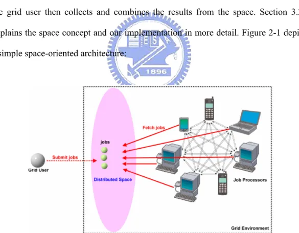
(27) that the entire network state needs to be maintained by the grid user itself, the grid user needs to know the condition of each of its neighbor node in order to pass jobs to the right neighbors for processing. This enormously increases the overall workload of the grid user.. 2.4.3 Space-oriented Architecture Space-oriented concept originates from the Linda programming model from Yale University[17]. It basically works as follows: a grid user submits jobs to a storage space on the network, each computing node then fetch jobs randomly from the space to process. After the processing completes, the results were passed back into the space, the grid user then collects and combines the results from the space. Section 3.2.4 explains the space concept and our implementation in more detail. Figure 2-1 depicts a simple space-oriented architecture:. Figure 2-3: a Space-oriented grid architecture. The space-oriented architecture seemed to be a panacea for grid computing. It has the advantage of both Client-Server and Peer-to-Peer architectures, yet it solved most of 14.
(28) the problems occurring in both models[17]. First, the space can be distributed across the network thus the SPF problem in 2.4.1 is settled. Secondly, all the compute node needs to register itself to the space upon start-up, thus the space manages and monitors the entire grid for the user. One important characteristic of space-oriented grids is that each compute node spontaneously fetch jobs FROM the space for processing, this differs from both the Client-Server and Peer-to-Peer models in that these two models push the jobs TO the compute nodes for process. This implies one more advantage: each node in a space-oriented architecture is allowed to leave the network at will. Due to the advantages the space-oriented architecture has over the other two models, mGrid chooses the space-oriented model as the underlying system architecture. Next, we discuss the lower-level communication protocol options.. 2.5. COMMUNICATION MODELS Grid nodes communicate with one another by means of communication protocol. Since different protocols bring about different effects on a grid system, we need to understand the features of each mechanism and decide which is most appropriate for grid computing systems. Two models are introduced in this section, namely Synchronous Transmission and Asynchronous Transmission.. 2.5.1 Synchronous Transmission Model Synchronous transmission refers to the fact that when a client requests a remote service call, the execution process is temporarily suspended until a reply is received 15.
(29) from the remote service. An implementation of such concept is the RPC(Remote Procedure Call) technology. Most commercial products such as SUN Grid[2] and IBM IntraGrid[18] are based on synchronous transmission mode.. 2.5.2 Asynchronous Transmission Model Asynchronous transmission, on the other hand, allows the service requestors to continue running after a request is sent, without blocking the entire program waiting for a reply. Examples of asynchronous transmission are MOMs(Message-Oriented Middleware) such as JMS(Java Messaging service)[19]. Synchronous and asynchronous transmission have advantages and disadvantages. The latter tends to be more robust to failures, while the former tends to be easier to develop with. So which transmission model is suitable for grid computing? Reference [19] uses a simple M/M/1 queuing model to prove that for a piece of program that is consisted mainly of parallel codes, the overall performance of the asynchronous model is better than the synchronous model. Furthermore, grid computing applications by nature are supposed to be parallel, submitting sequential programs to a grid is essentially senseless. Therefore we expect the majority of mGrid users will utilize our framework in solving parallel problems. With these facts in mind, we decided to use the asynchronous transmission model for mGrid Framework. Note that many commercial products are synchronous-based, thus we expect to have a better start than these grid solutions by choosing the correct transmission mode in advance.. 16.
(30) 2.6. RELATED WORKS Many international research institutes and companies have collaborated in developing various projects associated with grid computing. These projects can be horizontally classified into specific-grids, general-grids and grid middlewares. SETI@Home[12], Folding@Home[13] & GIMPS[14] are examples of specific-grids, meaning each of them solves only very specific problems. SETI@Home allows you to download a software that turns your computer into a node within SETI’s grid, this software analyzes radio telescope data using the CPU resources of your PC and transmits results back to SETI central server. Folding@Home uses a similar architecture to studies protein folding, misfolding, aggregation, and related diseases. GIMPS works in the same fashion only it conducts a different job. SUN Grid[2], IBM Intra Grid[18] and ALiCE[20] are examples of general-grids. These grid solutions do not restrict the logic of the applications running on-top of them. SUN Grid software typically bundles with SUN blade servers and allows jobs to be submitted to it. IBM Intra Grid provides an experimental worldwide-scale grid system accessible to all IBM employees. ALiCE is a java-based grid solution developed by National University of Singapore, applications such as protein modeling is written and tested with this framework. Finally, Globus toolkit[21], Legion[22], JXTA[23] and GridSim[24] are considered grid middlewares. Globus is an open system that provides a set of basic services. Users can build higher-level services using lower-level services. Globus is largely platform dependent and requires UNIX to run. Furthermore, its complicated infrastructure setup, application development and deployment created a high learning curve both in mastering and using Globus. Legion is a toolkit that treats all software. 17.
(31) and hardware in the grid as objects, and provide remote method calls between these objects. JXTA is a set of protocols developed by SUN Microsystems to ease the development of p2p application, different grid systems can be built by using these protocols. Last but not least, GridSim offers a complete solution in the simulation of grid networks. Most of the above researches are built on-top of the Client-Server architecture, and utilizes Synchronous transmission as underlying protocol. From sections 2.4 & 2.5 we pointed out that some of these technical decisions are probably not the best ones.. 2.7. SUMMARY This concludes our research background. We understand that there are multiple ways to super computing, and virtual grids offer a cost-effect and attractive option. Companies that cannot afford high TCO in purchasing grid solutions should consider about adopting grids that are purely software-based, such as mGrid. Virtual grids can be implemented using various design options, such as determining the system architecture and communication models. In sections 2.4 & 2.5 we used concrete research results that proves the following: ● Space-oriented Architecture is a good choice for grids ● For parallel computing, asynchronous transmission model is more appropriate. Finally we give an introduction on other related works of grids. The surveys and observations done in this chapter has influential impact in our design of mGrid Framework. In the next chapter we will walk you through our underlying implementation design in a thorough manner.. 18.
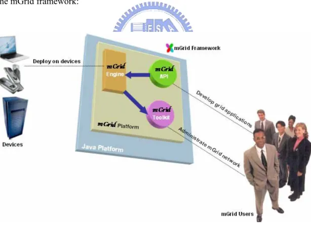
(32) 3.. SYSTEM ARCHITECTURE. 3.1. OVERVIEW The proposed solution in this thesis, named mGrid framework, is a low-cost, pure java-based, high-performance grid solution. mGrid attempts to migrate grid computing concept onto mobile devices(e.g. Personal Digital Assistants, Cellular phones) and onto large computational equipments(e.g. PCs, mainframes), which has minimum network connectivity support. Figure 3-1 depicts the macroscopic view of the mGrid framework:. Figure 3-1: Macroscopic view of mGrid framework. mGrid is consisted of four major portions. mGrid framework is consisted of four major portions: 19.
(33) ● mGrid Platform ● mGrid Engine ● mGrid Toolkit ● mGrid API mGrid Engines can be installed on devices with java support. The J2SE[4] and J2EE[4] version is fully operational, while the J2ME[4] version currently has minimal functions. Engines deployed on devices automatically constructs a mGrid network environment that support transaction, natural load-balancing and security. Application developers then use the mGrid API to compose various grid applications that utilizes the mGrid environment formed by the engines. Note that at least a single engine must be started for a mGrid network to be successfully built. We also provide a set of useful tools in the mGrid toolkit to allow easy monitoring and administrating of mGrid networks. In this chapter we will focus on the implementation methodologies and distributed algorithms of three items: mGrid Platform, mGrid Engine and mGrid Toolkit. In chapter 4 we will discuss the mGrid API in depth. We will emphasize on the J2SE and J2EE version of mGrid framework.. 3.2. mGrid PLATFORM Before we talk about mGrid Engine and mGrid Toolkit, we need to have some basic understanding of the platform itself. Note that both the engine and toolkit rely on the grid infrastructure constructed by the software components within mGrid platform. mGrid platform is an augmented version of SUN’s JINI network technology[8], by augmented version we mean that it provides additional features such as including 20.
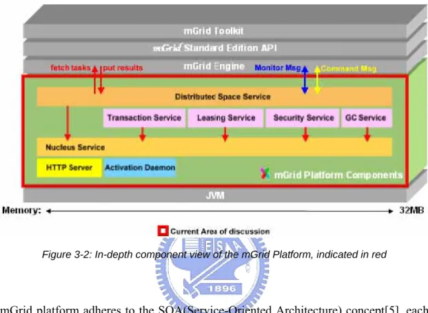
(34) more specialized service components dedicated to grid computing. Figure 3-2 shows the in-depth components that constitute the mGrid platform:. Figure 3-2: In-depth component view of the mGrid Platform, indicated in red. mGrid platform adheres to the SOA(Service-Oriented Architecture) concept[5], each component can exist as a remote service across the internet. For instance, we can start Nucleus service, Transaction service and Security service on computers A , B and C lying on the network. These services uses mGrid’s underlying protocol to search, discover and communicate with one another, as if they were running on the same machine. Protocol details will be described in section 3.2.3. SOA allows the stress of executing services to be evenly-distributed across the network, so that no single computer will be overloaded[5]. Now we introduce the individual components within mGrid platform. We begin with two lower-level components first: HTTP Server and Activation Daemon.. 21.
(35) 3.2.1 HTTP Server mGrid platform requires this facility because for many vital operations to realize, code needs to be dynamically downloaded from some remote service running somewhere on your network. The actual transmission of java code take place via the HTTP protocol. The implementation of our server is minimal, it only supports the GET operation, which is sufficient for code downloading. In general, any code that may need to be downloaded across the network has to be accessible from a HTTP server instance.. 3.2.2 Activation Daemon An activation daemon[6] is a piece of software which allows services that is invoked only rarely to essentially “hibernate”, and be automatically awakened when they are needed. Every service component will need to register itself with an activation daemon instance before running. Activation daemon has two major responsibilities: ● Service hibernation & de-hibernation: Manage the transition between active and inactive states for each service component. ● Service self-recovery: Restart a particular service after it crashes, restoring it to its previous state before the crash. We make use of the activation daemon software that comes with J2SDK 5.0[4]. At minimal, you will need to run an instance of activation daemon on each host that runs services. The daemon creates log files that contains information of the activable service which has registered itself to the daemon. State transition and crash recovery. 22.
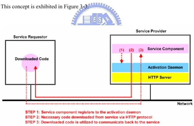
(36) relies on the information saved within those log files. The reason we apply activation daemons not only is because it is able to recover services after a crash, but also economizes the use of system resources by sending currently unused service components into “hibernate” mode. The down-side is that it adds an extra layer below each service component, efficiency is therefore decreased during a service’s initial start-up time by approximately 7.5%, but proposed no further decreases in subsequent service calls. We decided that this is a minor trade-off compared to the valuable capabilities it adds to our platform. In summary, the mGrid platform requires both HTTP server and activation daemon for services to pass necessary java codes across the network and to be self-recovery. This concept is exhibited in Figure 3-3:. Figure 3-3: Underlying code transmission steps for mGrid platform. Now that we understood how the lower-level code passing operates, we can start to probe into the upper-level service components provided by mGrid platform, namely Nucleus service, Transaction service, Leasing service, Security service, GC(Garbage 23.
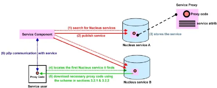
(37) Collector) service and Distributed Space service. Note that these services relies heavily upon the schemes described in sections 3.2.1 and 3.2.2. 3.2.3 Nucleus Service As the name implies, this service is the central core among the other services listed in the mGrid platform. A good analogy would be our solar system: The Nucleus service will be the sun, while the other services within mGrid platform are the planets constantly revolving around it, all using the functionalities the Nucleus service provides. You can think of Nucleus service as a kind of naming/directory service[7], it keeps track of all other mGrid services currently running on the network. However, it differs from traditional naming/directory services, which only provides simple string-object mapping, the Nucleus service supports java type search, i.e. You can search for a particular service using the interface it implements or any of its super-interfaces. The Nucleus service co-operates with other active services using the following steps: 1. A new mGrid platform service component searches for Nucleus services upon start-up, using IP multicast(in LAN) or unicast(beyond LAN). 2. The service component publishes the attributes and proxy code of the service it provides to the Nucleus service. 3. Nucleus service saves the attributes and proxy code. 4. A service user searches for a Nucleus service upon start-up, using IP multicast(in LAN) or unicast(beyond LAN). 5. The service user downloads the necessary proxy code it requires from the first Nucleus service it found. 6. The service user communicates with the service component in a p2p manner using the proxy code. 24.
(38) The above steps are illustrated in Figure 3-4:. Figure 3-4: How Nucleus service works with the other services from mGrid platform. Note that steps 2 and 5 in Figure 3-4 utilizes the underlying dynamic code download scheme introduced in section 3.2.1. Each Nucleus is also fault-tolerant, two mechanisms makes this possible: ● Each Nucleus service relies on the activation daemon described in section 3.2.2 to recover its state after a crash or restart. So you must run an activation daemon on each machine that runs a Nucleus. ● You have the option of running multiple instances of Nucleus service on your network. This redundancy allows unexpected failures of some Nucleus. It means as long as a single Nucleus lives, the mGrid platform can perform its duties as if no failure occurred, since each service user requires only a minimum of one Nucleus for proxy code downloading (see step 4 in Figure 3-4). This can be summarized into a simple mathematical formula:. (Max num of Nucleus failure tolerated) = (Total num of Nucleus started) – 1. 25. (1).
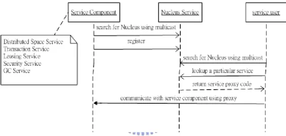
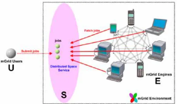
(39) Before discussing other service components in mGrid platform, we need to keep in mind that all the mGrid platform services needs to register itself to the Nucleus service upon start-up. Nucleus service keeps track of all mGrid service components currently running, and is capable of making them visible to service users, even if users have no previous knowledge of where the service components are on the network. This interaction between service components, service users and Nucleus is illustrated once more using an UML sequence diagram in Figure 3-5:. Figure 3-5: All service components needs to register with the Nucleus service upon start. 3.2.4 Distributed Space Service The Distributed Space Service serves as the job exchanging location for our grid system, all jobs are transmitted to and taken from a space. From this point on we shall refer the distributed space service as simply “space” for convenience. The concept of the space-oriented grid has been introduced in section 2.4.3, let’s add it with more detailed explanation here. Figure 3-6 shows the space-oriented grid concept:. 26.
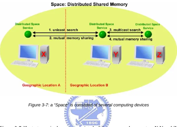
(40) Figure 3-6: The Space-oriented grid architecture used in mGrid Framework. The space works in a very simple manner. Suppose we have multiple users U, a single space S, and multiple Engines E: 1. U submits a series of parallel jobs to S. 2. E fetch the jobs randomly from S. 3. E process the jobs. 4. E put the results back to S. 5. U collects the results from the S for final presentation. Note that each space need to register itself to the Nucleus, refer to Figures 3-4 & 3-5. After a space has successfully registered itself to a Nucleus, it is then visible to both mGrid users and mGrid Engines for discovery and use. This space discovery process will be explained in more detail in section 3.3 later on. Right now we only need to know that a space acts as the central job exchanging ground for our grid Framework. So what is a space exactly? The simple answer is that a space is a piece of temporary memory residing on the 27.
(41) network that is consisted of multiple computers. Computers participating in the same space can share each other’s memory and storage space. Figure 3-7 depicts a space:. Figure 3-7: a “Space” is consisted of several computing devices. Figure 3-7 illustrates a single space consisted of three personal computers X,Y and Z. computer X sits at geographic location A, while computers Y and Z sits at geographic location B. By initiating a distributed space service on each of the computers, we combine them into a single logical space entity that is consistent and shares memory/storage resources, regardless of their actual geographical whereabouts. In other words, a space service is a virtualization middleware which connects computer memories across the network. Space service uses multicast to search for other space services in the same LAN, while unicast is used if the other space services are located outside of the LAN. A space only supports three simple operations: 1. Fetch 2. Put and 3. Read. These three very basic operations proves to be extremely useful and sufficient. Suppose we have a Genetic Algorithm computation on hand, each step can be first disassembled 28.
(42) into tasks. Each task is then Put into the space by the client. The engines Fetch these tasks from space and does the processing, then it Put the results back into the space. Finally, the client Read the results in space and reassemble them for presentation. A space utilizes the other services, namely Transaction service, Leasing service, Security service and GC(Garbage-Collector) service, to provide add-on functionalities such as safe-transaction, space garbage-cleaning, space access-authorization and leasing. These final four mGrid platform service components will be introduced in sections 3.2.5, 3.2.6, 3.2.7 and 3.2.8 below.. 3.2.5 Transaction Service A transaction service needs to register with the Nucleus before being used by other service components, see section 3.2.3. Transaction service provide the ACID properties to data manipulations. In simple words, it allows a series of operations to complete altogether, if a single operation in the whole series fail, the transaction fails, and everything gets rolled-back to its initial state. Our implementation of Transaction service supports the 2-phase commit protocol. Note that the distributed space service utilizes the transaction service to insure data integrity, the space is required to discover the transaction service through the Nucleus (consult section 3.2.3) before it can be transaction-enabled. Figure 3-8 illustrates the transaction steps in mGrid platform using UML sequence diagram. The interaction between mGrid Client, the Distributed space service, Transaction service and mGrid Engines is the center focus, we will not show transaction-unrelated steps such as the discovery of services.. 29.
(43) Figure 3-8: Transaction service supports the 2-phase commit protocol: Either all or none!. Let us explain Figure 3-8 step by step. Assume tasks T1 and T2 belong to the same transaction, this means T1 and T2 must both complete successfully or neither will. Transaction service keeps this principal in mind and constantly polls Engines A and B using the 2-phase commit protocol. If both Engines A and B succeed in processing T1 and T2 consecutively, then the transaction service sends the commit message to both engines, finishing up the transaction. If either engine fail to finish processing a task, then the transaction is considered a failure and roll-back procedure is taken. The system returns to its initial state and re-processes T1 and T2 again. We use a simple pseudo-code in the next page to demonstrate the transaction algorithm described above:. 30.
(44) T1, T2 : belong to the same transaction; Transacted processing of tasks(T1, T2) { Step1. T1, T2 are put into the space. Step2. T1, T2 are registered to the Transaction service to be managed. Step3. Engine A and Engine B fetch T1 and T2 for processing. Step4. Engine A and Engine B are registered to the transaction service. While(Engine A || Engine B has not completed processing) { Step5. Transaction service asks Engines A,B if the processing has completed? } Step6. commit the transaction and the client read the results from space. } Listing 3-1: Transaction algorithm pseudo-code. The Space service needs to discover the Transaction service before using it, the discovery procedure is described in Figures 3-4 and 3-5, section 3.2.3.. 3.2.6 Leasing Service Leasing Service needs to register itself before being used. All objects sent to a space has a lease time attribute, indicating its TTL(Time-To-Live) within a space. A Leasing service manages a hashtable of object-TTL pair, and constantly removes the expired objects from a space. This allows the unused objects to be recycled and memory resources could be released, thus mitigates the loading of the entire grid. However, lease time have the option to be renewed to prevent it from being discarded by the Leasing service.. 31.
(45) 3.2.7 Security Service mGrid platform supports policy-based security model. The Security service reads a policy file before the mGrid platform starts, this policy file include all the policies that has to be obeyed. The following are two simple examples of a policy file:. grant { permission java.security.AllPermission "", ""; }; Listing 3-2: Policy File that allows total access to mGrid platform from anyone.. grant { permission java.security.AllPermission "", ""; permission java.net.SocketPermission "192.168.11.2", "connect, refuse"; }; Listing 3-3: Allows total access except for incoming connection from IP 192.168.11.2. Security service provides a static method of authentication and authorization for mGrid platform. Currently the platform has been initially tested using the total access policy.. 3.2.8 GC Service (Garbage-Collector Service) GC service is short for Garbage-collector service. Like all the other service components in mGrid platform, it needs to register itself to the Nucleus before being used. GC service differs from the Leasing service described in section 3.2.6 in that it can force all the objects to be cleaned up, regardless of their leasing time. This service is useful in situations when the entire platform needs to be restarted. Other uses of GC Service would be specifying a group of unwanted objects, such as 32.
(46) illegal submitted tasks. The GC service removes these tasks without effecting the other regular operation of mGrid platform. So far we have completed the introduction of the underlying mGrid Platform, and should have a brief understanding of how a space-oriented grid works(see section 3.2.4). mGrid Engine is another key portion of our framework that is built on-top of mGrid Platform. In the following section we will introduce the mGrid Engine.. 3.3. mGrid ENGINE mGrid Engine is built on-top of the mGrid Platform. Figure 3-9 shows the in-depth components that constitutes mGrid Engine:. Figure 3-9: In-depth component view of the mGrid Engine, indicated in red. Engines can be deployed on a variety of devices with java support. After successful deployment and execution, engines allow a disperse set of devices to link together and form a virtual supercomputing environment that shares CPU, memory, storage, file. 33.
(47) resources and so forth. We call this environment the mGrid Environment. Developers then utilizes the mGrid APIs (see chapter 4) to write various grid applications that access the resources harnessed within mGrid environment. These applications includes protein modeling, ray-tracing and prime number searching programs. Now that we have a high-level idea of mGrid Engine’s role, we begin introducing the inner-level components that propels the engine, starting with the core of the Engine: Engine Kernel.. 3.3.1 Engine Kernel Engine Kernel is the main component which enables the engine to communicate with the underlying mGrid Platform. The engine kernel has four major responsibilities: ● Initializes the engine, search for the space service instance provided by the mGrid Platform (see section 3.2.4 for distributed space service introduction). ● Fetches tasks from space, pass them to the Generic Task Processor for processing, then put results back to space. ● Acts as the middleman for monitoring messages sent to mGrid Toolkit (see section 3.4 for Toolkit monitoring details). ● Acts as the middleman for control messages sent from mGrid Toolkit (see section 3.4 for Toolkit controlling details). If we look at engine kernel technically, an engine kernel assists the engine to search for space instances within mGrid Platform, and constantly fetch tasks from the space for processing. Figure 3-10 illustrates how an engine kernel interacts with a space using UML sequence diagram: 34.
(48) Figure 3-10: Engine kernel constantly fetch tasks from space.. A mGrid client uses multicast to search for the Nucleus service (section 3.2.3) and use it to lookup a space instance(section 3.2.4). After obtaining the space, the client program then feed the space with tasks that needs to be processed by the mGrid Environment. On the other side, engine kernel also uses multicast to search for a Nucleus and use it to lookup a space, then randomly fetch any available tasks that currently resides within the space. When the processing is completed, a result object will be fed into the space by the kernel, where it will be read by the client and reassembled with other results objects for presentation. Note that the engine kernel only fetches the tasks from the space, it does not process it! Instead, the Generic Task Processor introduced in the next section manages the task processing.. 35.
(49) 3.3.2 Generic Task Processor (GTP) After the engine kernel fetched a task from space, this task is passed to the Generic Task Processor(GTP) for processing. As the name implies, the GTP is generic enough to handle different sorts of logical calculations, this is achieved through the dynamic class loading feature of the java programming language. In other words, when the GTP receives a task, the task’s computational code will be dynamically loaded into the processor. The GTP does not have any previous knowledge of the task logic that it will process, everything loads in on the fly. A naïve version of GTP pseudo-code looks like listing 3-4, it simply fetches a task from space, process it, then feed the result back to space:. While(true) { aTask = EngineKernel.takeTaskFromSpace(); result = aTask.process(); EngineKernel.putResultInSpace(result); println(“a task is processed”); } Listing 3-4: A naïve GTP implementation pseudo-code. The above GTP pseudo-code has a critical flaw. What if the engine fails after it fetched a task but did not successfully process it? This task would then be lost. For a system with high-reliability demand this is not an acceptable situation. Therefore our GTP implementation makes use of mGrid Platform’s Transaction service (consult section 3.2.5 for detailed description on how transaction service 36.
(50) works). By integrating transaction service into GTP, we ensure a highly-reliable grid system. A modified version of GTP pseudo-code is listed below:. While(true) { TransactionService txn = Platform.createTransactionService(); aTask = EngineKernel.takeTaskFromSpace(); if(aTask == null) { txn.abort(); return; } result = aTask.process(); if(result == null) { txn.abort(); return; } EngineKernel.putResultInSpace(result); txn.commit();. println(“a task is processed”); } Listing 3-5: A modified GTP implementation pseudo-code – better solution. Listing 3-5 illustrates GTP with transaction support. If an engine fail to fetch a task from space, or if task processing fails, the transaction service will abort the transaction and attempt to roll-back the entire computation. Only when the calculation is guaranteed to be successful, will the transaction be considered finished and committed. In summary, GTP acts as the central processing unit in mGrid Engine.. 37.
(51) 3.3.3 JVM Monitor JVM Monitor digs the local machine’s JVM profile for display in the mGrid Engine graphical user interface. Furthermore, it periodically sends heartbeat messages in the form of EngineInfoEntry containing the JVM attributes to a remote mGrid Toolkit software for administration purposes. All messages generated by the JVM Monitor goes through the engine kernel, which in turn passes the message to the distributed space service on mGrid Platform, where it is read by mGrid Toolkit for display. JVM attributes includes JRE version, operating system name, OS patch level, JDK version and so forth. See section 3.4.1 for EngineInfoEntry details.. 3.3.4 Machine Monitor Machine Monitor reflects the local machine’s CPU and memory status every 1000ms. The status is displayed in the mGrid Engine graphical user interface. Furthermore, it periodically sends heartbeat messages in the form of EngineInfoEntry containing the machine’s latest status to a remote mGrid Toolkit software for monitoring purposes. All messages generated by the Machine Monitor goes through the engine kernel, the kernel passes the message to the distributed space, where it is read by mGrid Toolkit for display. Machine status includes CPU and memory usage level. See section 3.4.1 for EngineInfoEntry details.. 3.3.5 Engine Command Listener Engine Command Listener waits for commands sent from the mGrid Toolkit, such as shutting down an engine or setting processing condition thresholds. Command 38.
(52) messages sent from mGrid Toolkit first go through the engine kernel, which in turn passes them into the distributed space service on the mGrid Platform, where they are fetched by the Engine Command Listener component for analysis and execution. Command messages are concealed in an EngineCommandEntry class. See section 3.4.2 for further information regarding EngineCommandEntry. At this point, we have completed the technical introduction of mGrid Engine. However, engines are by themselves a full-fledged software with simple-to-use graphical user interfaces. Appendix has a thorough user tutorial on mGrid Engine. Last but not least, we discuss mGrid Toolkit in the next section. mGrid Toolkit is an utility tool that simplifies the administration of any mGrid network environment.. 3.4. mGrid TOOLKIT mGrid Framework provided a simple-to-use utility tool called mGrid Toolkit, which enables easy administrating and monitoring of existing mGrid environments.. Figure 3-11: In-depth component view of the mGrid Toolkit, indicated in red 39.
(53) Figure 3-11 illustrates the tools included in mGrid Toolkit, namely Network tool, Workflow tool, System tool and Help tool. At this stage we have fully-implemented the Network tool, thus it will be the focus of this section. But before we start to introduce the components within the Network Tool, we need to understand how mGrid Toolkit initially connects with mGrid Engines. Keep in mind that engines might randomly spread across WAN and different LANs. There are two possible situations: Scenario 1. The toolkit resides in public network (WAN). Scenario 2. The toolkit resides in private network (LAN).. Figure 3-12: mGrid Toolkit and Engine initial linking steps - When the Toolkit resides in WAN. Figure 3-12 illustrates the first scenario. In order for a Toolkit residing in public network to communicate with Engines (which might reside in both public or private networks), the Toolkit needs to publish its location information, namely IP/port, to the space service of the mGrid Platform. Engines A and B read this location information object and actively establish a socket connection TO the toolkit using the IP/port pair. 40.
(54) Toolkits in this scenario waits passively for the socket connection. However, if the toolkit resides in a private network, as stated in scenario two, the algorithm needs to be slightly modified. Figure 3-13 depicts this situation:. Figure 3-13: When the Toolkit resides in LAN, the algorithm needs to be slightly modified. In Figure 3-13, the toolkit resides in a private network. If we naïvely apply the algorithm steps given in Figure 3-12, initial socket connections between the toolkit and engines A & B will fail, for in this scenario the toolkit’s IP address is a private one, socket connections simply cannot be made to a private IP address! Instead, engines A and B must now publish their location information (IP/port) to the distributed space service running on mGrid Platform. The toolkit read engine A and B’s IP/port objects from the space, and then actively establishes socket connections consecutively TO mGrid Engines A and B using corresponding IP/port pairs. Engines in this scenario waits passively for the incoming connection. Combining the algorithms described in Figures 3-12 and 3-13, mGrid Toolkit is 41.
數據

![Figure 2-1: a Client-Server based grid architecture[16]](https://thumb-ap.123doks.com/thumbv2/9libinfo/8026231.161144/25.892.269.614.554.858/figure-a-client-server-based-grid-architecture.webp)
+7
相關文件
A factorization method for reconstructing an impenetrable obstacle in a homogeneous medium (Helmholtz equation) using the spectral data of the far- eld operator was developed
Hence, we have shown the S-duality at the Poisson level for a D3-brane in R-R and NS-NS backgrounds.... Hence, we have shown the S-duality at the Poisson level for a D3-brane in R-R
Now we assume that the partial pivotings in Gaussian Elimination are already ar- ranged such that pivot element a (k) kk has the maximal absolute value... The growth factor measures
• Most programs tend to access the storage at any particular level more frequently than the storage at the lower level.. • Locality: tend to access the same set
• We will look at ways to exploit the text using different e-learning tools and multimodal features to ‘Level Up’ our learners’ literacy skills.. • Level 1 –
Service Level Agreement – ensure at least 99.7% availability of the WiFi service, support four-hour response time and four-hour service recovery with active monitoring,
• If we know how to generate a solution, we can solve the corresponding decision problem. – If you can find a satisfying truth assignment efficiently, then sat is
In this thesis, we develop a multiple-level fault injection tool and verification flow in SystemC design platform.. The user can set the parameters of the fault injection
