國
立
交
通
大
學
網路工程研究所
碩
士
論
文
WAVE/DSRC 多車道自由流電子收費系統之
實作與驗證
Development and Evaluation of a WAVE/DSRC-based
Multilane-free-flow Electronic Toll System
研 究 生:邱紹閔
指導教授:簡榮宏 博士
WAVE/DSRC 多車道自由流電子收費系統之實作與驗證
Development and Evaluation of a WAVE/DSRC-based
Multilane-free-flow Electronic Toll System
研 究 生:邱紹閔 Student:Shao-Min Chiu
指導教授:簡榮宏博士 Advisor:Dr. Rong-Hong Jan
國 立 交 通 大 學
網 路 工 程 研 究 所
碩 士 論 文
A Thesis
Submitted to Institute of Network Engineering College of Computer Science
National Chiao Tung University in partial Fulfillment of the Requirements
for the Degree of Master
in
Computer Science
September 2012
Hsinchu, Taiwan, Republic of China
I
WAV E / D S R C 多 車 道 自 由 流 電 子 收 費 系 統
之 實 作 與 驗 證
研究生:邱紹閔
指導教授:簡榮宏 博士
國立交通大學 網路工程研究所
摘要
智慧型交通運輸系統(Intelligent Transportation System, ITS)能改善運輸系 統、提 升用 路安 全並 提供 各式 各 樣 的商業 服 務 。公 速公路電子 收費系 統 (Electronic Toll System, ETC)是 ITS 中重要的應用之一,多車道自由流電子收費 系統為目前發展的趨勢。然而,傳統通訊技術如紅外線、RFID 等皆不足以滿 足 多 車道自由流系 統 對於通 訊 品質的 需 求。在 本篇 文章中,我 們發展 一 WAVE/DSRC 多車道自由流電子收費系統,將電子收費系統劃分成預約區及收 費區,車輛進入預約區先使用控制頻道(control channel, CCH)向收費站請求服務 頻道(service channel, SCH),在進入收費區後使用該服務頻道與收費站進行交易。 收費站中透過多個路邊節點分別使用不同的服務頻道,採用輪詢(polling)的方式 對進入交易區的車輛進行免競爭(contention free)交易扣款程序。本篇文章使用 Estinet7.0 進行實驗模擬,結果顯示本系統相較於傳統電子收費系統能提供更可 靠的服務品質,並藉由探討系統中不同參數設定所造成影響,提供開發者及實 作人員做參考。
II
Development and Implementation of a WAVE/DSRC
based Multilane-free-flow Electronic Toll System
Student: Shao-Min Chiu Advisor: Rong-Hong Jan
Institute of Network Engineering National Chiao Tung University
Abstract
Intelligent Transportation System (ITS) provides efficient transport system and wide range of commercial applications. Highway Electronic Toll Collection (ETC) system is one of the most important applications in ITS. Multi-lane Free Flow (MLFF) ETC system is the trend of development in the world. However, traditional communication technologies, such as infrared and RFID, cannot satisfy the requirements in MLFF ETC systems. In this thesis, we develop a WAVE/DSRC contention free polling based ETC system. The toll area is divided into reservation zone and transaction zone. Vehicles entering reservation zone request toll gate for a reserved service channel on control channel. When vehicles entering transaction zone, they use reserved service channel to pay the tolls. The multiple roadside units (RSUs) with independent service channels in toll gate use polling based contention free transaction process to toll vehicles in transaction zone. We conduct experiments by Estinet7.0, the commercial version of NCTUns, and show the reliability of tolling service in our system. We also discuss effects of variable parameter setting and give some suggestions for further system developers.
III
誌謝
首先我要感謝指導教授簡榮宏博士在學生碩士生涯內給予的關切與指導, 不論是學術上或是待人處世方面皆受益良多,並在學術研究的過程中提供適切 建議與方向,使我能夠順利的完成碩士研究。同時也感謝口試委員交通大學資 訊學院陳健教授、易志偉教授以及工研院資通所曾蕙如博士對於學生碩士論文 的批評與建議,使本論文能更趨完善,並且感謝陳健教授以及安凱學長在百忙 之中仍抽空與我討論,在此深表感激。 感謝計算機網路實驗室的所有成員,不管事在課業上的相互提攜或是生活 上的互相關心,融洽的研究環境使我能維持愉悅的心情並專注於學術研究上, 也感謝在求學生涯中曾經鼓勵支持我的朋友們。最後要感謝家人無微不至的照 顧與關愛,讓我能無牽無掛地專注於學業並順利完成研究。在此將此文獻給身 邊所有的人,將完成論文的喜悅與大家一同分享。IV
Contents
Abstract (in Chinese) ...I Abstract (in English) ...II
Acknowledgements ...III Contents ...IV
List of Figures ...VI List of Tables ...VII
Chapter 1 Introduction ... 1
Chapter 2 Survey on ETC and Communication Technologies ... 5
2.1. ETC Architecture ... 5
2.2. Implements of ETC Systems in World ... 6
2.3. Communication Specification ... 9
2.4. Summary ... 13
Chapter 3 System Architecture ... 14
3.1. Introduce to the Multi-Channel ETC ... 14
3.2. Challenges of the system ... 18
About contention ... 18
About channel allocation ... 22
About polling scheduling ... 24
How to determine the lengths of the two regions ... 26
Chapter 4 Design and Development ... 28
4.1. How to contention ... 28
4.2. Channel Allocation ... 29
4.3. Polling Schedule ... 30
4.4. How to poll ... 31
V
Chapter 6 Experimental Results ... 38
6.1. With vs. without Reservation ... 38
6.2. Analysis for without Reservation ... 42
6.3. Analysis for with Reservation ... 42
Chapter 7 Conclusions ... 49
VI
Lists of Figures
Figure 1-1 Two types of ETC systems 2
Figure 2-1 WAVE DSRC channel frequency 9
Figure 2-2 WAVE/DSRC system architecture 10
Figure 2-3 Sync Interval in WAVE/DSRC [16] 11
Figure 2-4 Architecture of 1609.11 [17] 12
Figure 3-1 Multi-channel contention free ETC architecture 14
Figure 3-2 Packet flow of channel reservation process 16
Figure 3-3 Flow chart of channel reservation and transaction process 18 Figure 3-4 Mathematical analysis of channel reservation successful probability 22
Figure 3-5 Channel allocation scheme 23
Figure 3-6 Mathematical analysis of transaction successful probability 26
Figure 4-1 Channel allocation method in our ETC system 30
Figure 4-2 Polling schedule method in our ETC system 31
Figure 5-1 Cumulative probability distribution function with λ=1 34
Figure 5-2 Extreme case at highway scenario 35
Figure 6-1 Transaction successful ratio 40
Figure 6-2 Distribution passing length of transaction zone 41
Figure 6-3 Distribution of transaction request times 42
Figure 6-4 Effect of variable length of reservation zone 45
Figure 6-5 Effect of variable number of T-RSUs 46
VII
List of Tables
Table 2-1 Implements of ETC systems in world 8
Table 3-1 Parameters for contention mathematical Analysis 21
Table 3-2 Parameters for polling scheduling mathematical Analysis 25
Table 5-1 Simulation parameters 37
1
Chapter 1
Introduction
Intelligent Transportation System (ITS) combining technologies, such as sensing technology, wireless communication technology, mobile computing technology and so on, provides efficient transport system and wide range of commercial applications. Highway Electronic Toll Collection (ETC) system is one of the most important applications in ITS. Through wireless communication between infrastructures and in-vehicle devices, vehicles are able to pay tolls without stopping when passing toll plaza. The establishment of ETC system needs no additional space and labor power. ETC system also provides benefits such as emissions reduction, human resources saving, lower management costs and traffic congestion easement.
According to ETC systems used in the world, they can be classified into two types: Single-lane Free Flow (SLFF) and Multi-lane Free Flow (MLFF) as shown in Figure 1-1 [1]. There is no limitation of barriers in two types of ETC systems so that vehicles do not need to stop when passing toll plaza. The MLFF ETC systems have fewer limitations than SLFF ETC systems. In Figure 1-1 (a), vehicles are able to change lanes arbitrarily without any limitations and pass the transaction area with high traveling speed in MLFF ETC systems. In SLFF ETC systems, toll plazas still exist in transaction area shown in Figure 1-1 (b).
2
Vehicles should follow lower traveling speed when passing transaction zone based on limitation of toll plaza for safety reason. However, the requirements of communication technology in MLFF ETC systems is serious due to more high traveling speed vehicles passing transaction area at the same time. The bandwidth and transmission delay in MLFF ETC system are stricter than in SLFF ETC systems. In order to guarantee reliability of tolling process and system capacity in MLFF ETC systems, the high quality communication technology is necessary.
(a) Single-lane free flow (b) Multi-lane free flow Figure 1-1 Two types of ETC systems
Many existing communication technologies are appropriate for ETC systems, mainly to Dedicated Short Range Communication (DSRC). DSRCs are specifically designed for automotive use including public safety and private operations between V2I/V2V [2] short
3
range wireless communication environments. In Taiwan, ETC system uses infrared-based DSRC technology for transaction process. Infrared-based DSRC is easily influenced by environmental factors such as raining or haze. In addition, the limitations of transmission range and vehicle speed are other drawbacks of infrared-based DSRC technology. It cannot satisfy the requirements of capacity and reliability in MLFF ETC systems. E-Tag is a RFID-based DSRC product using in Taiwan ETC system. But it is also impacted by metal and not compatible with other ITS applications. The U.S. Federal Communication (FCC) assigns 5.9 GHz bandwidth for wireless access in vehicular environment (WAVE) which has been standardized by Institute of Electrical and Electronics Engineers (IEEE) known as 802.11p. WAVE/DSRC supports several independence channels and multi-channel access operation. It reduces wireless communication setup time in IEEE 802.11 so that it can provide more immediate service. It is more appropriate for high speed and high vehicles destiny network environment in MLFF ETC systems.
Through communication between OBU and RSU, vehicle drivers are able to pay a toll without stopping when passing toll gate. When vehicles enter predefined transaction area, the communications between OBUs and RSUs will exchange information, including authentication, types of vehicles, user account and so on, through specific channel for transaction process. In order to deal transaction fails caused by failure of communication or non-OBU vehicles, the enforcement system is required to recognize the violation vehicles and forward vehicles’ information to back-end server for further manual toll charge.
However, the most existing DSRC based ETC systems only use single channel for transaction process with low transmission bandwidth and long communication delay. It is not appropriate for high traveling speed and high vehicle destiny network environment in MLFF ETC systems. In addition, the medium access control of existing ETC system is based on contention. There is no guarantee that each vehicle is able to access channel successfully for
4
transaction process. The interference caused by other applications, such as safety applications or emergency messages on control channel in WAVE/DSRC, also reduces successful transaction probability and decrease the reliability of ETC system.
In this thesis, we develop a MLFF ETC system using multi-channel multi-RSU and contention free polling based communication model. It takes advantage of independent channels access and multi-channel access operation in WAVE/DSRC. In our ETC system, transaction area is divided into reservation zone and transaction zone in order to reduce the interference caused by contention between vehicles for communication delay reduction and improvement of successful transaction probability. We conduct experiments by Estinet7.0 [3], the commercial version of NCTUns. The experimental results show that this communication model effectively increases system capacity and transaction reliability. It guarantees the success of transaction process even in harsh environments with high packet error rate.
The rest of this thesis is organized as follows. We describe architecture of typical ETC and implements of ETC system in the world and WAVE/DSRC communication technology. In section 3, we introduce the developed contention-free polling based ETC system and mathematical analysis about the challenge in the ETC system. In section 4, we describe our implement method of above challenge for the developed ETC system. In section 5 and 6, experimental design and results are evaluated and discussed. Finally, we conclude this thesis in section 7.
5
Chapter 2
Survey on ETC and Communication
Technologies
2.1. ETC Architecture
A typical ETC system is consists of two components: 1) Automatic Vehicle Identification and Transaction Processing and 2) Violation Enforcement [4]. The Automatic Vehicle Identification and Transaction Processing component involves RSUs, OBUs, and wireless communication between them. The Automatic Vehicle Identification process distinguishes different types of vehicles and determine toll amount. When vehicles enter the transaction area, they will pay the toll through wireless communication between RSU and OBU exchanging necessary information to complete transaction process. The Violation Enforcement component involves use of digital camera and automatic license plate recognition (ALPR) technology. Once a vehicle passes through transaction area without tolling, the camera captures images of violation vehicle and reports its license plate number obtained by ALPR technology to backend server for further manual tolling process. The accuracy of Violation Enforcement impacts credibility of ETC system. To ensure the high accuracy of Violation Enforcement, there are some limitations in ALPR technology. If
6
vehicles are far away from the camera, ALPR technology cannot recognize license plates and map to violation vehicles correctly. Therefore, the length of transaction area in ETC system is limited. In Taiwan, the length of transaction region is up to 10 meters.
2.2. Implements of ETC Systems in World
In Taiwan, Far Eas Electronic Toll Company uses Austria EFKON system which adopts 850nm infrared technology for transaction process [5]. Now it adopts RFID technology and infrared technology simultaneously. Vehicle drivers should install an OBU or RFID tag and pass a toll plaza up to 70km/hr.Singapore is one of the earliest countries using Electronic Road Pricing (ERP) [6]. In order to reduce vehicles use during periods of peak congestion, ERP adopts congestion pricing which means the charge relies on the situation of traffic congestion for each road segment. If traffic congestion is more serious in some road segments, vehicle drivers require paying more charges when passing these road segments. The gantry is infrastructure in ERP system which is similar to RSU in traditional ETC system. When vehicles pass through a gantry, the transaction process is completed through communication between gantry and vehicles using 2.45GHz microwave. Since there is no limitation in transaction area under gantry, the speed limitation in ERP system is up to 120km/hr.
In Japan, 5.8GHz DSRC drafted by Association of Radio Industries and Businesses (ARIB), which is under control Japanese government [7][8], is the communication technology for transaction process. Japanese ETC system adopts SLFF ETC system architecture that vehicles should follow separated lanes or toll plaza when passing transaction area. ETC system is popular in Japan not only using in highway but also in gas
7 station, vehicle parking or shopping.
Melbourne City Link project in Australia adopts MLFF ETC system architecture [9]. The tolling criterion relies on vehicle classification instead of traveling distance. The ETC system adopts PERMID system from SAAB Combitech Company which uses 5.8GHz DSRC technology.
In Germany, LKW-MAUT is an ETC system designed for goods vehicles based on traveling distance [10]. Violation Enforcement system cannot reach high accuracy in DSRC based ETC system due to natural environment. It applies GPS-GSM communication technology for transaction process. Since The OBU collects amount of GPS information and then transmit to back-end server through GSM network. According to road segments and traveling distance calculated by GPS information, the back-end server decides tolls of each vehicle. By assistance of map mapping technology, it can be located through DSRC technology in some area with low GPS signal strength. Unlike DSRC based ETC systems, LKW-MAUT use less RSUs and save construction costs. But the performance of violation enforcement system is relatively poor.
FrsTrak ETC system use 902-925MHz bandwidth microwave communication technology in Orange County, California, USA [11]. Vehicle capacity in FrsTrak ETC system is up to 2500 vehicles per hour per lane. The accuracy of AVI technology also reaches 99.9% in even high vehicle destiny environment. In United State, E-ZPass is the most famous ETC system mainly using in New York City for road, bridge and highway tolling [12]. The interoperability of E-ZPass makes it become the most widely used ETC system. Vehicle drivers put a RFID transponder on car windshield and pass through toll gate with speed least than 60 km/hr.
In Canada, Highway 407, known as the 407 Express Toll Route (ETR), is one of the earliest examples of MLFF ETC system in the world [13]. In 407, there are sets of cameras
8
and transponders which using 900MHz bandwidth to deal transaction process without any tolling booths. If vehicles without transponders use Highway 407, video toll charge recognizes user identifies based on ALPR technology and mail bills to vehicle drivers. When traveling Highway 407, the speed limitation is up to 100 km/hr.
The ETC system can be classified into two types based on tolling method: toll plaza and open road tolling [14]. Toll plaza is similar to traditional toll collection systems. Vehicles slow down when passing a toll gate and pay tolls through wireless communication between RSU and OBU. Open road tolling is defined as toll collection that complete through gantry or other infrastructures with no limitation on loads. Vehicles pass these infrastructures with speed limitation following by general road restrict just for safety reason, not for technology limitation. In Table 2-1, it shows the summary of ETC systems in the world.
Table 2-1 Implements of ETC systems in world
System Types of Tolling Communication Technology ETC architecture Taiwan FET Toll Plaza Infrared/RFID SLFF
Singapore ERP Open road 2.45GHz Microwave
MLFF
Japan - Toll Plaza 5.8GHz DSRC SLFF
Australia City Link Open road 5.8GHz DSRC MLFF
German Toll Collect Open road GPS/GSM MLFF
Unite States : Orange Country
FasTrak Toll Plaza 905 – 925 MHz MLFF
Unite States : New York
E-ZPass Toll Plaza 915MHz SLFF
9
2.3. Communication Specification
DSRC technology is designed for public safety and private operation in vehicle networks and focus on short range communication. The frequency assigned for DSRC is not the same in variable countries. In Unite Sate, FCC allocates 5.850 to 5.925GHz band range for in-vehicle communication to enhance road safety. The 75MHz bandwidth is divided into 7 small operation channels and assigns 172, 174, 176, 178, 180, 182 and 184 channel numbers to each as shown in Figure 2-1. Channel 178, called control channel (CCH), is used to communicate safety and emergence message for road safety. Other six channels, called service channel (SCH), is typically used for IP-based service and private operation applications. Channel 172 and Channel 184 are often reserved for public safety applications [15].
Figure 2-1 WAVE DSRC channel frequency
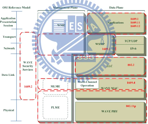
WAVE/DSRC is used to describe the DSRC technology which consists of IEEE 802.11p and the suit of IEEE 1609.x standards. Figure 2-2 illustrates WACE/DSRC system architecture. It has advantages such as low transmission delay, high transmission range and high transmission rate compared to other DSRC technology. Vehicle drivers should make a
10
response to surrounding environment in limited time due to quickly change of vehicle network topology. In order to avoid accidents and enhance warning message for traffic safety, the requirement of transmission delay is strict in in-vehicle communication. The lower layer in WAVE/DSRC uses IEEE 802.11p standard. The physical layer utilizes orthogonal frequency-division multiplexing (OFDM) method to defense interference. There is no concept of BSS existing in IEEE 802.11. The 802.11p MAC layer abandons authentication, association or date confidentiality service to allow direct communication between WAVE devices and prevent the time delay from BSS establishment.
11
The suits of IEEE 1609.x standards are upper layer of MAC, which relies on IEEE 802.11p to establish a uniform specification between V2V communication and V2I communication. IEEE 1609.1 describes resource management and the access point interfaces between WAVE stack and application layer. IEEE 1609.2 defines safety components such as safety message format and related process in WAVE system. IEEE 1609.3 defines network layer protocol and management mechanism in WAVE system. The Wave Short Message Protocol (WSMP) is defined in IEEE 1609.3 to reduce transmission time between WAVE devices. In WAVE/DSRC, it allows devices to switch channel in one or more radio for different application requirements. The channel switching specification is defined in IEEE 1609.4. The channel access time is divided into sync intervals shown in Figure 2-3. Each sync interval is consists of CCH interval (CCHI) and SCH interval (SCHI) with the same default value 50ms. For different application requirements, there are four channel access methods that allows variable time duration of SCHI and CCHI in one sync interval.
Figure 2-3 Sync Interval in WAVE/DSRC [16]
IEEE 1609.11 belongs to upper layer of WAVE DSRC and is defined the specification of data exchange in Electronic Payment Service (EPS) between Roadside Unit (RSU) and Onboard Unit (OBU). The ETC system is a kind of applications in ETS. Actually, ETC
12
system has been working for years. The specifications defined in ISO14906 and in ISO 15628 have been existed to ensure interoperability of ETC systems with different sponsors. For WAVE-based ETC systems, it only needs to replace communication medium by DSRC and modify the necessary details. Thus, 1609.11 describe the communication mechanism between payment applications to exchange information such as identity, payment certificate. The architecture is shown in Figure 2-4.
Figure 2-4 Architecture of 1609.11 [17]
The main components in the architecture are Application Core for applications related procedure and WAVE Interface Application Layer (WIAL) for communication Application Core and WAVE stack. WIAL and, in some systems, the Payment Service exchange
13
information through WME service Access Point (SAP) and WSM SAP defined in IEEE 1609.3. Payment Service also provides service for Application Core or WIAL based on different payment systems. Different payment systems use different data transmission processes. According to data exchange mode in EPS, it can be classified into Direct Communication Mode and Indirect Communication Mode. In addition, it is also classified into four type, payer action without approval, payer action pre-approval, payee action without approval and payee action pre-approval, based on weather needs for the approval from payee or payer in transaction process.
As mentioned before, ETC is one of EPS applications and existing some specifications in ISO. To ensure be compatible for ISO 14906/15628, 1609.11 defines the architecture shown as Figure 2-4 and requires to use Direct or Indirect Communication Mode and Payer Payee Pre-approval Mode.
2.4. Summary
The capacity of existing DSRC based ETC system using single channel for transaction process is not enough for instantaneously huge traffic flow with high traveling speed. And the trend of ETC systems is integration of ITS systems and MLFF ETC systems so that traditional DSRC technologies such as RFID and infrared are not appropriate. WAVE/DSRC is a communication technology which is designed for high speed, high dynamic network topology. The features of multi-channel operation and low transmission latency delay make it satisfy the requirements. Thus, development of WAVE/DSRC based MLFF ETC system with high system capacity which takes advantages of multi-channel operation and compatibility of ITS is important.
14
Chapter 3
System Architecture
3.1. Introduce to the Multi-Channel ETC
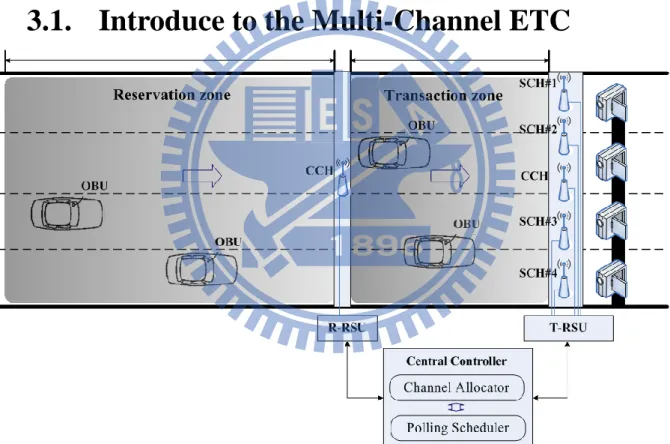
Figure 3-1 Multi-channel contention free ETC architecture
Figure 3-1 shows the architecture of developed contention-free polling based ETC system. The contention based communications between R-RSU and vehicles are used for
15
SCH reservation. When vehicles enter reservation zone and receive channel reservation beacon, called R-Beacon, broadcasted from R-RSU on CCH, vehicles attempt to access medium and send request for channel reservation to R-RSU on CCH. Each T-RSU uses independent SCH to poll vehicles for transaction process in transaction zone. According to the polling based communication mode and several independent SCH, T-RSUs play roles of coordinators for vehicles’ transaction processes. One of the T-RSUs uses control channel (CCH) to service vehicles which are failed to channel reservation before entering transaction zone. The other T-RSUs use independent SCHs to poll vehicles for transaction process.
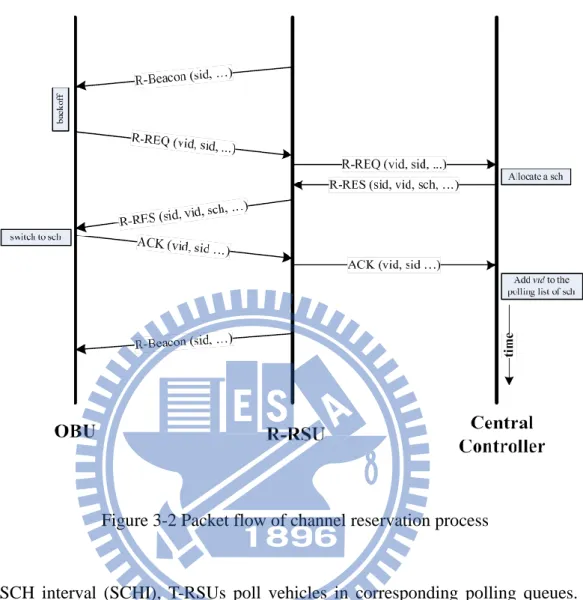
R-RSU periodically broadcasts R-Beacon packets on CCH covering both transaction zone and reservation zone. The necessary information such as identify authentication or timestamp is including in R-Beacon. Vehicles in reservation zone without channel reservation receiving R-Beacons will send a channel reservation request, called R-REQ, to R-RSU on CCH. There may be several vehicles that attempt to send R-REQ packets to R-RSU at the same time. These vehicles will contend to each other and try to access medium based on MAC protocol. After R-RSU receives the R-REQ packet from a vehicle, the channel allocator, which is designed for coordination of SCH usage, chooses an appropriate SCH number for the requested vehicle and then sends an R-RES packet back to the vehicles. As the requested vehicle received the R-Response packet, vehicle sets its own SCH number to the reserved SCH number in R-RES packet and sends an ACK packet back to R-RSU. R-RSU will add vehicles to the corresponding polling queue of T-RSU based on the reserved channel number after receiving the ACK packet. The packet flow of channel reservation is shown in Figure 3-2.
16
Figure 3-2 Packet flow of channel reservation process
In SCH interval (SCHI), T-RSUs poll vehicles in corresponding polling queues. The polling scheduler decides polling queue sequence. It means the order of vehicles which wait to be polled is decided by polling scheduler. The polling scheduler may happen in the end of CCHI or at the beginning of each polling cycle in SCHI. In first case the polling sequence is the same in one SCHI. In second case the order of polling sequence is decided in run time. Before T-RSU sending a polling packet, the polling scheduler chooses an appropriate vehicle in polling queue to be polled.
17
receiving the polling packet, they will send back an ACK packet to the corresponding T-RSU based on their own SCH number on SCH. The transaction process is complete when T-RSU receives the ACK packet from the polled vehicle.
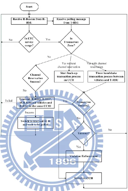
If vehicles cannot reserve channel successfully before entering transaction zone, the one of T-RSUs will use contention base access scheme for backup transaction process to these vehicles on CCH. The backup transaction process is a three handshake process similar to other contention based ETC systems. The flow chart of the ETC system including channel reservation process and transaction process is shown in Figure 3-3.
18
Figure 3-3 Flow chart of channel reservation and transaction process
3.2. Challenges of the system
About contention
19
before they entering transaction zone. The length of reservation zone is one of factors that influences channel reservation successful probability. The longer reservation zone means more vehicles stay in reservation zone for longer time. After received R-Beacon, vehicles in reservation zone without channel reservation will attend to access medium to send the request to R-RSU at the same time. The contention of channel reservation between vehicles will be more serious due to the longer length of reservation zone.
We conduct a simple analysis of channel reservation successful ratio to illustrate the above problem [18]. Assume there is x-lane highway ETC system and length of the reservation zone is 𝑙𝑅. The R-RSU broadcasts R-Beacon at fixed interval time 𝐼𝐵.The
vehicle arrival rate of each lane is λ. The average vehicle speed is v. Thus, the number of vehicles in reservation zone 𝑁𝑅 can be expressed as following:
𝑁𝑅 = 𝑥 ∙ 𝜆 ∙ 𝑙𝑅∙1𝑣 (1)
Each vehicle in reservation zone that attempt to send packets has the same probability, means the probability is reciprocal of the number of vehicle. If there are more vehicles in reservation, lower probability is. Actually, there is no sense about less than 1 vehicle. The number of vehicles in reservation zone 𝑁𝑅 is an average value which means it is a probability distribution. Here we use Poison probability distribution to describe the number of vehicles in reservation zone. The probability that exact x vehicles in reservation zone can be express as following:
Pr (x = k) =𝑁𝑅𝑘 ∙ 𝑒−𝑁𝑅
𝑘! (2)
By using the probability distribution Pr (x = k) and the transmission probability which is reciprocal of the number of vehicles, we obtain one transmission successful ratio 𝑃𝑆:
𝑃𝑆 = ∑𝑚 1𝑘Pr(𝑥 = 𝑘)
20
In 802.11p, if medium is busy, vehicles require to wait until medium is free and a random back-off time, called contention window. The contention window initializes at an initial value 𝐶𝑊𝑚𝑖𝑛. If next time that vehicles try to access but medium is still busy, the contention window value will double until reach a maximal value 𝐶𝑊𝑚𝑎𝑥. The initial value and maximal value of contention windows are defined in IEEE 802.11p based on the priority level. Each packet transmission time 𝑡𝑇𝑥 equals to 𝑅𝐵
𝑇𝑥 where symbol B is packet size and
𝑅𝑇𝑥 is transmission rate. When medium is busy, means a vehicle is transmitting, the other vehicles require to wait until the transmission over. The average waiting time of each busy medium access is half of packet transmission duration 12𝑡𝑇𝑥. The expected time 𝑡𝑠 of one
time successful transmission can be expressed as following:
𝑡𝑠 = 𝑡𝑇𝑥 + ∑ [ 𝑃𝑠(1 − 𝑃𝑠)𝑥∙ (𝑚𝑖𝑛{2𝑥−2∗ 𝐶𝑊 𝑚𝑖𝑛, 𝐶𝑊𝑚𝑎𝑥} +𝑥2𝑡𝑇𝑥)] 𝑚 𝑥=1 (4)
In CCHI, vehicles should complete a three-handshake process for channel reservation. It requires at least three times successful packets transmission. If successful packet transmissions between vehicles and R-RSU are less than three in a CCHI, vehicles fail to reserve channel and wait to receive next R-Beacon to start the other channel reservation process until leaving reservation zone or channel reservation success. In a CCHI, there are
times that packet transmission happened between vehicles and R-RSU. The times
can be obtained by duration time of CCH 𝑡 and expected transmission time 𝑡𝑠 from equation (4):
= 𝑡𝑐𝑐ℎ𝑡
𝑠 (5)
21
we assume the average waiting time 12𝐼𝐵 for vehicles to receive first R-Beacon when
entering reservation zone. The expected number of R-Beacon reception will rely on the remaining length of reservation zone and vehicle speed. R-RSU sends R-Beacon in fixed interval. Each packet reception has probability, called packet error rate 𝑃𝑃𝐸𝑅, to be failed due to surrounding environment effect such as raining or fogs. Thus, the channel reservation successful ratio P𝑅 can be expressed as following:
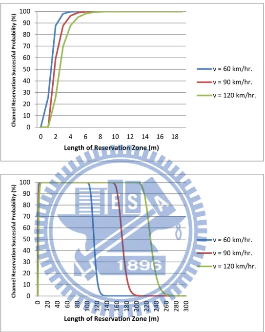
P𝑅 = 1 − (𝑃𝑃𝐸𝑅+ (1 − 𝑃𝑃𝐸𝑅) ∑2𝑦=0[( 𝑦 ) 𝑃𝑠𝑦(1 − 𝑃𝑠)𝑇𝑐𝑐ℎ−𝑦]) max (𝑙𝑅− 𝑣 2𝐼𝐵 𝑣 ∙ 1 𝐼𝐵, 0) (6)
Table 3-1 Parameters for contention mathematical Analysis
λ 1 𝑣𝑒ℎ𝑖𝑐𝑙𝑒𝑠 𝑙𝑎𝑛𝑒𝑠 ∙ 𝑠⁄ V 25 𝑚⁄ 𝑠 𝐶𝑊𝑚𝑖𝑛 3 slots 𝐶𝑊𝑚𝑎𝑥 7 slots Slot time 0.000013 s B 1000 bytes 𝑅𝑇𝑥 3 Mb⁄ 𝑠 𝑡 0.05 s
22
Figure 3-4 Mathematical analysis of channel reservation successful probability
About channel allocation
In our ETC system, there are multi T-RSUs set in transaction zone for polling-based transaction process. T-RSUs have each own polling queue with variable polling queue length.
0 10 20 30 40 50 60 70 80 90 100 0 2 4 6 8 10 12 14 16 18 C hanne l Re se rv at ion Succe ss ful P robabi lit y (%)
Length of Reservation Zone (m)
v = 60 km/hr. v = 90 km/hr. v = 120 km/hr. 0 10 20 30 40 50 60 70 80 90 100 0 20 40 60 80 10 0 12 0 14 0 16 0 18 0 20 0 22 0 24 0 26 0 28 0 30 0 C hanne l Re se rv at ion Succe ss ful P robabi lit y (%)
Length of Reservation Zone (m)
v = 60 km/hr. v = 90 km/hr. v = 120 km/hr.
23
When vehicles entering reservation zone and requesting for channel reservation, R-RSU should decide a T-RSU to service them based on vehicle location and vehicle speed and each corresponding polling queue state. In Figure 3-5, vehicle A and vehicle B request for channel reservation. The SCH#2 is an intuitive solution for these requests due to the shorter polling queue length. In fact, we should consider not only polling queue length but also vehicle speed and vehicle location when designing a channel allocator. In a situation, vehicle C and vehicle D are also in polling queue #2 and almost leaving transaction zone without operating transaction process. Vehicles in polling queue #1 are far away from transaction zone with lower speed, means they will stay in transaction for a longer time. If we add vehicle A and vehicle B into polling queue #2, the T-RSU should spend time polling vehicle A and vehicle B even they are still far away from transaction zone. For vehicle C and vehicle D, they have fewer times to be polled due to longer polling queue length by adding vehicle A and vehicle B into it. It may decrease the transaction successful probability.
24
About polling scheduling
The goal of polling scheduling is increasing transaction successful probability. In polling based transaction process, transaction successful probability and the expected polling times are positive correlation, means the transaction successful probability is increasing due to more polling chance. A vehicle expected polling times is impacted by many factors such as polling queue length, vehicle speed and the number of T-RSUs. We conduct an analysis about transaction successful probability. We assume that there are 𝑁𝑠 T-RSUs and each T-RSU has the same polling queue length 𝐿𝑄 which can be obtained from equation (1) and
equation (6):
𝐿𝑄 =𝑁𝑁𝑅 ∙ 𝑃
𝑠𝑐ℎ (7)
The polling based transaction process is three handshake processes, so time duration of one polling process 𝑡𝑝 equals to 3𝑡𝑇𝑥. The transaction process starts when vehicle entering
transaction zone and receiving the first polling packet from T-RSU. This waiting time can is related to polling queue length 𝐿𝑄 and current channel interval. If vehicles enter transaction
zone in SCHI, the time 𝑡𝑤𝑎𝑖𝑡𝑖𝑛𝑔_ they only need to wait is relying on polling queue length:
𝑡𝑤𝑎𝑖𝑡𝑖𝑛𝑔_𝑠 = 12∙ 𝐿𝑄∙ 𝑡𝑝 (8)
If vehicles enter transaction zone in CCHI, they should wait until channel changing to SCHI.
𝑡𝑤𝑎𝑖𝑡𝑖𝑛𝑔_ = 12𝑡 + 𝑡𝑤𝑎𝑖𝑡𝑖𝑛𝑔_𝑠 (9)
The total time vehicles stay in transaction zone is equal to 𝑙𝑇
25
of transaction zone. If transaction zone is not long enough before vehicle receiving first polling packet, we say that the time duration 𝑡𝑠𝑡 vehicles spend for transaction process is 0. We assume vehicle entering transaction zone in SCHI or in CCHI has the same probability. Thus the time duration 𝑡𝑠𝑡 can be expressed as following:
𝑡𝑠𝑡 = 12(𝑚𝑎𝑥 {𝑙𝑇
𝑣 − 𝑡𝑤𝑎𝑖𝑡𝑖𝑛𝑔_ , 0} + 𝑚𝑎𝑥 { 𝑙𝑇
𝑣 − 𝑡𝑤𝑎𝑖𝑡𝑖𝑛𝑔_𝑠 , 0}) (10)
For compatibility of other existing commercial applications which also share SCH bandwidth, our ETC system should not use all of SCHI for contention free period. The ratio 𝑟 𝐹𝑃 is contention free period of SCHI that is reserved for our ETC system. Thus, we can
obtain the expected polling times of one vehicle in transaction zone:
𝑝𝑜𝑙𝑙𝑖𝑛𝑔= 12𝑡𝑠𝑡∙ 𝑟 𝐹𝑃∙𝐿 1
𝑄 ∙ 𝑡𝑃 (11)
If there is one packet failed in three handshake process, the transaction is failed for this time. There are expected 𝑝𝑜𝑙𝑙𝑖𝑛𝑔 times three handshake process for transaction process. Thus, the total transaction successful probability 𝑃𝑇 can be expressed as:
𝑃𝑇 = 1 − (1 − (1 − 𝑃𝑃𝐸𝑅)3)𝑇𝑝𝑜𝑙𝑙𝑖𝑛𝑔 (12)
Table 3-2 Parameters for polling scheduling mathematical Analysis
𝑙𝑅 100 m
𝑙𝑇 5 m
26
Figure 3-6 Mathematical analysis of transaction successful probability
How to determine the lengths of the two regions
As shown in Figure 3-4, the longer reservation zone may not increase channel reservation successful ratio. The contention is the main problem. In longer reservation zone, the more vehicles will attempt to access medium and cause collision. Even vehicles have more time to reserve channel in long reservation zone, the effect of lower successful packet transmission probability is more serious. The other problem is polling queue length also increasing with length of reservation zone as shown in equation (7). In equation (11), the long polling queue length 𝐿𝑄 causes less expected polling times 𝑝𝑜𝑙𝑙𝑖𝑛𝑔 and decreases the transaction successful probability. However, channel reservation successful probability is low in short reservation zone shown as Figure 3-4. The collision is relieved due to fewer vehicles in shorter reservation zone, but the transmission times of channel reservation request are also decreasing.
95 95.5 96 96.5 97 97.5 98 98.5 99 99.5 100 60 70 80 90 100 110 120 Tr an sact io n Su cc e ssf u l Pr o b ab ilty (% ) vehicle speed (m/s) 1# T-RSU 2# T-RSUs 3# T-RSUs 4# T-RSUs
27
In equation (10) and equation (11), the expected polling times and the transaction successful probability are increasing with long transaction zone. If ETC system using fewer T-RSUSs, the transaction zone should increase due to longer polling queue length in equation (7). However, the limitation of transaction zone is ALPR technology as described in above chapter.
28
Chapter 4
Design and Development
4.1. How to contention
The MAC layer of WAVE/DSRC follows 802.11e.In 802.11e, there are two medium access schemes: Enhance Distributed Channel Access (EDCA) and HCF Controlled Channel Access (HCFF). EDCA extends from DCF and supports Quality of Service (QoS). To support QoS, packets from upper layer send into one of four access categories with distinct transmission priority. The packets in access categories with higher transmission priority have shorter contention window. AC_BK is the access category with lowest priority, it usually accounts for transmission of network background flow. The second is AC_BE which means best effort for general network applications with no packet scheduling. AC_VI and AC_VO is the highest priority level for transmission of video or audio date.
In WAVE/DSRC, RSU broadcasts WAVE Service Advertisement (WSA) messages periodically with highest priority level AC_VO as service provider. If vehicles receiving WSA message are interest of that service, they send a request to RSU for service register. The similar procedure so does our ETC system. In reservation zone, R-RSU broadcasts R-Beacon and response, and vehicles send back request and ack message. All of these messages have highest priority same as WSA message. There is no consideration of vehicles’
29
speed and locations in our ETC system because we desire our ETC system is compatible in WAVE/DSRC standard without modification.
4.2. Channel Allocation
WAVE/DSRC standard does not define how to decide an appropriate channel for a multi-channel access scheme. The major goal of our ETC system is reliability of transaction process. The SCHs that channel allocator assigns to vehicles should let vehicle have high probability to be polled for more times. The expected polling time is related to polling queue state, vehicle speed and vehicle location as described in above chapter. Here we apply load balance policy which only considers polling queue state in our ETC system. When vehicles requesting for channel reservation, channel allocator selects SCH number with the shortest corresponding polling queue length in T-RSU. If there are many T-RSUs have the shortest polling queue length, channel allocator will select by T-RSU ID in sequence. For example, in Figure 4-1, vehicle A, B, C and D reserved channel to R-RSU in sequence. The channel allocator first assigns SCH#3 which has lowest polling queue length to vehicle A. After added vehicle A into polling queue #3, polling queue #2 and polling queue #3 has the same queue length. When vehicle B requests for channel reservation, channel allocator assigns SCH#2 to vehicle B. Then it will assign SCH#3 to vehicle C after adding vehicle B into polling queue #2. Finally, the length of all there polling queue are the same. Thus channel allocator will assign polling queue #1 to vehicle D when it starts channel reservation.
30
Figure 4-1 Channel allocation method in our ETC system
4.3. Polling Schedule
As describing in above, WAVE DSRC follows 802.11e MAC layer. In 802.11e, there is no description about polling list management. In our ETC system, the polling scheduler of each T-RSU should decide the sequence of polling queue in run time or at end of CCHI. For guaranty of reliability, all vehicles should be polled at least one time before them leveling the transaction zone. In our ETC system, the polling scheduler runs at the end of CCHI and sorts queues based on expected deadline time of vehicles. If vehicles are going to leave transaction zone, then we will put them to the front of queue. For example, in Figure 4-2, there are four vehicles A, B, C, and D waiting to be transacted. Vehicle A has higher speed than vehicle C so that it will leave transaction zone faster. Thus the polling scheduler will put vehicle A in front of vehicle C in polling queue. Although vehicle B and vehicle D is not in transaction zone, we still put them into polling queue and try to poll them. The reason is that we cannot make sure when them will enter transaction zone due to GPS error and acceleration caused by drivers.
31
Figure 4-2 Polling schedule method in our ETC system
4.4. How to poll
Each time T-RSU sends polling packet to the vehicle which is on the top on polling queue and then move it to the end of queue. For example, in Figure 4-2, after T-RSU send polling packet to vehicle A and then move A to the end of queue. The sequence of polling queue becomes C, B, D, A. The T-RSU will delete vehicles in polling queue in two cases: transaction success or times out. If there is no packet error in three handshake process between T-RSU and vehicles, the transaction process is complete and then T-RSU deletes vehicles from polling queue. Otherwise, T-RSU still keeps vehicle in polling queue even it has been passing transaction zone without being transacted. Thus, we should have some mechanisms to determine whether vehicles in polling queue are still in transaction zone or reservation. Here we use expected leaving time as evaluation criteria. If the expected leaving time of vehicles in polling queue plus a threshold ∆ is earlier than current time, we say that these vehicles have been time out without be transacted and delete them from polling queue. The threshold ∆ is calculated by lower bound of speed limitation 𝑣𝑚𝑖𝑛 and length of total ETC system which equals to length of reservation zone 𝑙𝑅 plus length of transaction zone
32
𝑙𝑇 as following, where ɛis a system parameter to ensure correctness of system in GPS error situation.
∆= ɛ ∙𝑙𝑅 + 𝑙𝑇
33
Chapter 5
Experimental Design
In this thesis, we focus on the system based on WAVE DSRC in normal environment even in harsh environment whether it is still reliable. Our ETC system will compare to the ETC system which using single channel contention based transaction scheme for most existing ETC systems. The compared ETC system uses only CCH to process transaction operation which just similar to our ETC system transaction operation on SCH. According to the experiment results, we will show that our ETC system is more appropriate for MLFF architecture and more reliable than single channel contention based ETC system. Then, the results also show the effect of varied length of reservation zone and the reliability in distinct numbers of T-RSU situations.
Sometimes, there is huge number of vehicles passing a toll gate at the same time. ETC systems should be able to service these overwhelming vehicles simultaneously and transact them as many as possible. In simulations, the vehicle arrival process is commonly modeled as Poisson process [19]. For Poisson process of vehicle arrival rate, the vehicle inter-arrival time distribution is an exponential variable. The vehicles arrival rate is defined as an average number of vehicles that appearing at each lane per second in this thesis. Base on exponential distribution, the cumulative probability function is shown as Figure 5-1. 1. The probability
34
that less than one vehicle arrival at a lane in one second is 64%. It still has 0.68% probability that more than five vehicles arrive in one second.
Figure 5-1 Cumulative probability distribution function with λ=1
To illustrate the effect of overwhelming vehicles to ETC systems, we define two cases: normal case and extreme case. In normal case, vehicles arrive on each lane based on exponential distribution with λ = 1. In extreme case, to eliminate the uncertain factors, vehicles have the same speed 120km/hr., it is the maximum speed limitation of highway in Taiwan. We let 5 vehicles arriving at a lane in one second with fixed speed 120km/hr., about 6.67 meters distance between two vehicles at one lane. The extreme case scenario is shown in Figure 5-2. 0 0.1 0.2 0.3 0.4 0.5 0.6 0.7 0.8 0.9 1 0 1 2 3 4 5 Cu m u lativ e Pr o b ab ili ty Number of Vehicles
35
Figure 5-2 Extreme case at highway scenario
In real world, there are many kinds of ITS applications based on WAVE DSRC such as road traffic safety applications on CCH or commercial applications on SCH. For road traffic safety applications, vehicles broadcast safety messages including periodical beacon exchange and non-periodical emergence safety message on CCH as mentioned above. These kinds of message transmission on CCH we call them background flow relative to our ETC system. The background flow on CCH is trigged from several independent applications from upper layer. In the simulation, we assume that background flow is produced at average 25ms with Poisson probability distribution on CCH. Vehicles whether inside or outside reservation zone will all produce background flow. Background flow packets have the same header field as WSA messages. On SCH, not only ETC systems but also other commercial application share bandwidth. To guarantee existing applications working successfully, the ETC system cannot occupy all SCHI for contention free polling. In our simulation, we use only 40% of SCHI as contention free period (CFP) and the reserved bandwidth save for other commercial applications.
36
In theory, packet error ratio of WAVE DSRC is only influenced by distance due to signal attenuation and multipath interference. The longer distance between transistor and receiver is, the packet error is higher. Actually, the previous observation of WLAN is not suit for WAVE DSRC due to various network environments which are relatively higher speed and the quick change of network topology. The packet error ratio is impacted by not only distance but also quality of wireless communication device and surrounding environment such as raining or haze. In previous work [20], the filed test in highway scenario shows that the packet error rate of single packet transmission in WAVE DSRC is about 9% at 100 meters. In [21] - [25], weather condition also impact throughput and packet error rate in wireless communication. ETC systems should ensure that the transaction operations can work any time including in bad weather situation. Thus, we define two type of environment in our simulation: general environment and harsh environment [22]. In general environment, there are no raining or other weather conditions that will influence wireless communication. The only factor that will influence packet error rate is quality of WAVE/DSRC devices. In harsh environment, the weather condition, such as snow or haze, is serious so that the packet error rate is increasing. In experiment we assign 5% packet error rate in general environment and 15% packet error rate in harsh environment.
We conduct the simulation using Estinet7.0, the commercial version of NCTUns. The simulation scenario is in a 1km four-lane highway scenario. Vehicles arrive on each lane at average 1 second per vehicle. There are 4 T-RSUs using independent SCH for transaction procedure and 1 R-RSU using CCH for channel reservation setting in the middle of the highway. The transmission range of each vehicle and each RSU is 300 meters and the transmission rate is 3 Mb/s. The more detail parameter is shown as Table 5-1.
37
Table 5-1 Simulation parameters
Simulation parameters Value
Length of highway 1 km
Lane width 3.5 m
Number of lanes 4
Number of T-RSUs 4
Length of reservation zone 10 m
Length of transaction zone 8m
Average vehicle speed 90 km/hr.
Deviation of vehicle speed 10 km/hr.
Vehicle speed probability distribution Gaussian
Vehicle arrival rate 1 vehicle/s‧lanes Vehicle inter-arrival time distribution Exponential
R-Beacon interval 100 ms
Priority level of Reservation message AC_VO
CFP of SCH 40%
Background flow interval 25 ms
Priority level of background flow AC_BE
38
Chapter 6
Experimental Results
There are 4 types of network environment as describing in previous chapter, normal case with general environment, normal case with harsh environment, extreme case with general environment and extreme case with harsh environment, to represent various situations in real world. In this chapter, we will show the experimental results in three parts. First, we compare our ETC system with the ETC system without reservation scheme which means it use contention based transaction process. Two ETC systems use the same protocol stack, WAVE/DSRC. The major goal is to show the improvement of reliability in the developed ETC system. Second, we focus on the ETC system without reservation scheme and realize why using reservation scheme is more reliable. Finally, the analysis for proposed ETC system with variable length of reservation zone and number of T-RSUs gives some suggestion for developers about how to decide these important parameters of the ETC system.
6.1. With vs. without Reservation
The transaction successful ratio is increasing with length of transaction zone in two ETC systems shown in Figure 6-1. Vehicles stay in transaction zone for longer time due to longer
39
length of transaction zone. It has lager probability to be transacted for more times. The transaction successful ratio of ETC system without reservation scheme is lower than ETC system with reservation scheme in all types of network environments. It means the reservation scheme is effective in increasing reliability of ETC systems. In Figure 6-1 (a), the ETC system without reservation scheme needs at least 10 meters transaction zone for 90% transaction successful ratio in all network environments. In Figure 6-1(b), the transaction successful ration in ETC system with reservation scheme is almost 100% in all network environments even with 6 meters transaction zone.
(a) Without reservation 70 75 80 85 90 95 100 6 8 10 12 Tr an sact io n Su cc e ssf u l R atio (% )
Length of Transaction Zone (m)
Normal Case with General Environment Normal Case with Harsh Environment Extreme Case with General Environment Extreme Case with Harsh Environment
40
(b) With reservation
Figure 6-1 Transaction successful ratio
Figure 6-2 shows distribution of vehicle passing length before be transacted in transaction zone. If vehicles can be transacted early, means passing less length in transaction zone, the probability of expected vehicles transacted times is higher. In Figure 6-2 (a), the ETC system without reservation scheme requires about 7 meters for almost 100% vehicles to be transacted successfully. In Figure 6-2 (b), vehicles in ETC system with reservation scheme only need to pass 2 meters for transacted. It means that vehicles in ETC system with reservation scheme have larger expected transaction times for higher reliability.
70 75 80 85 90 95 100 6 8 10 12 Tr an sact io n Su cc e ssf u l R atio (% )
Length of Transaction Zone (m)
Normal Case with General Environment Normal Case with Harsh Environment Extreme Case with General Environment Extreme Case with Harsh Environment
41
(a) Without Reservation
(b) With Reservation
Figure 6-2 Distribution passing length of transaction zone 0 10 20 30 40 50 60 70 80 90 100 1 2 3 4 5 6 7 8 Cu m u lativ e Pr o p o rtion o f veh ic le s
Passing Length of Transaction Zone (m)
Normal Case with General Environment Normal Case with Harsh Environment Extreme Case with General Environment Extreme Case with Harsh Environment 0 10 20 30 40 50 60 70 80 90 100 1 2 3 4 5 6 7 8 Cu m u lativ e Pr o p o rtion o f veh ic le s
Passing Length of Transaction Zone (m)
Normal Case with General Environment Normal Case with Harsh Environment Extreme Case with General Environment Extreme Case with Harsh Environment
42
6.2. Analysis for without Reservation
It shows transaction request time distribution in 8 meters length transaction zone ETC system without reservation scheme in Figure 6-3. Most of all vehicles only send transaction request one time due to the limitation of transaction zone length. It causes lower transaction successful ratio and necessary of longer length of transaction zone.
Figure 6-3 Distribution of transaction request times
6.3. Analysis for with Reservation
Table 6-1 shows the transaction successful ratio in variable transaction length ETC system with reservation scheme. The results in general environments show in Table 6-1 (a) and the results in harsh environments show in Table 6-1(b). In normal case in both general and harsh environments, the transaction successful ration is 100% due to small number of vehicles. In extreme case, transaction successful ratio increases slightly with length of transaction zone due to more transacted probability. But when increasing length of
0 10 20 30 40 50 60 70 80 90 100 0 1 2 3 4 5 Per ce n tage o f To tal R e q u e st Ti m e s (% ) Request Times
Normal Case with General Environment Normal Case with Harsh Environment Extreme Case with General Environment Extreme Case with Harsh Environment
43
reservation zone, the transaction successful ratio is decreasing.
Table 6-1 Transaction successful ratio with distinct cases in varying environments (a) General environment
General environment (Packet error rate: 5%)
6 8 10 12
Normal Extreme Normal Extreme Normal Extreme Normal Extreme
10 100 100 100 100 100 100 100 100
30 100 99.9153 100 100 100 100 100 100
50 100 99.8305 100 100 100 100 100 100
(b) Harsh environment
Harsh environment (Packet error rate: 15%)
6 8 10 12
Normal Extreme Normal Extreme Normal Extreme Normal Extreme
10 100 99.322 100 99.8305 100 99.5763 100 99.9153
30 100 95.7093 100 99.7458 100 99.4077 100 99.4077
50 100 92.2881 100 99.8305 100 99.9153 100 99.9153
More vehicles in longer reservation zone will contend to access channel on CCHI at the same time. In Figure 6-4 (a), the reservation request times are increasing with larger vehicles density and the more serious effect of surrounding environment. In Figure 6-4 (b), the longer reservation zone can enhance channel reservation successful ratio, but the ratio cannot achieve 100% even with 50 meters reservation zone. The reasons show in Figure 6-4 (c), although vehicles have increasing reservation request times with length of reservation zone, the contention will cause the decreasing of channel reservation successful ratio.
The other drawback of large reservation zone is the longer polling queues show in Figure 6-4(d). T-RSUs need more time to poll all vehicles in polling queue. The polling times
44
of each vehicle will decrease due to the longer polling time. It will cause the decrease of transaction successful ratio.
(a) Distribution of reservation request Times
(b) Channel reservation successful ratio 0 10 20 30 40 50 60 70 80 90 100 0 1 2 3 4 5 6 Per ce tan ge o f To tal R e q u e st Ti m e s (% ) Request Times
Normal Case with General Environment Normal Case with Harsh Environment Extreme Case with General Environment Extreme Case with Harsh Environment 70 75 80 85 90 95 100 10 30 50 Per ce tan ge o f To tal R e q u e st Ti m e s (% )
Length of Reservation Zone (m)
Normal Case with General Environment Normal Case with Harsh Environment Extreme Case with General Environment Extreme Case with Harsh Environment
45
(c) Average request times
(d) Average polling queue length
Figure 6-4 Effect of variable length of reservation zone
In Figure 6-5 (a), we show the relationships between transaction successful ratio and 0 1 2 3 4 5 6 7 8 10 30 50 A ve rag e R e q u e st Ti m e s
Length of Reservation Zone (m)
Normal Case with General Environment Normal Case with Harsh Environment Extreme Case with General Environment Extreme Case with Harsh Environment 0 0.5 1 1.5 2 2.5 3 10 30 50 A ve rag e Poll in g Qu e u e Le n gth
Length of Reservation Zone (m)
Normal Case with General Environment Normal Case with Harsh Environment Extreme Case with General Environment Extreme Case with Harsh Environment
46
number of T-RSUs. When using more than 2 T-RSUs, the transaction successful ratio is higher than 99.5%. Using only one T-RSU will cause the significant decrease on transaction successful ratio. The reason is the longer polling queue length shown in Figure 6-5 (b).
(a) Transaction successful ratio
(b) Average polling queue length
Figure 6-5 Effect of variable number of T-RSUs 93 94 95 96 97 98 99 100 1 2 3 4 Tr an sact o p n S u cc e ssf u l R atio (% ) Number of SCH
Normal Case with General Environment Normal Case with Harsh Environment Extreme Case with General Environment Extreme Case with Harsh Environment 0 1 2 3 4 5 6 7 1 2 3 4 A ve rag e Poll in g Qu e u e Le n gth Number of SCH
Normal Case with General Environment Normal Case with Harsh Environment Extreme Case with General Environment Extreme Case with Harsh Environment
47
In Figure 6-6, we show the distribution of vehicle passing length before be transacted in transaction zone with 1 T-RSU and 4 T-RSUs. In 1 T-RSU case, vehicles should passing about 5 meters to guarantee transaction process success. In 4 T-RSUs case, vehicles only require to pass about 3 meters in transaction zone for guaranty of transaction process. It means that the reliability is increasing with number of T-RSUs in ETC system. We can enhance the reliability by using more T-RUSs on independent SCH.
(a) 1 T-RSU case 0 10 20 30 40 50 60 70 80 90 100 1 2 3 4 5 6 7 8 Cu m u lativ e Pe o p o rtion al o f Veh ic le s
Passing Length of Transaction Zone (m)
Normal Case with General Environment Normal Case with Harsh Environment Extreme Case with General Environment Extreme Case with Harsh Environment
48
(b) 4 T-RSUs case
Figure 6-6 Distribution passing length of transaction zone 0 10 20 30 40 50 60 70 80 90 100 1 2 3 4 5 6 7 8 Cu m u lativ e Pe o p o rtion al o f Veh ic le s
Passing Length of Transaction Zone (m)
Normal Case with General Environment Normal Case with Harsh Environment Extreme Case with General Environment Extreme Case with Harsh Environment
49
Chapter 7 Conclusions
In this thesis, we have developed a WAVE/DSRC based contention-free ETC system. The transaction area is divided into reservation zone for channel reservation and transaction zone for transaction process. Vehicles use contention access scheme for channel reservation in reservation zone and pay tolls without contention through multiple T-RUSs using several independent SCHs. The simple mathematical analysis shows relationships between length of reservation zone and channel reservation successful probability. In additional, some challenges about channel allocator and polling scheduler have been discussed. We conduct the experiments by Estinet7.0, the commercial version of NCTUns. The experimental design and results show that the developed ETC system is more reliable than other single channel contention based ETC system. Finally, we also have discussed effect of variable system parameter setting, such as length of reservation zone and the number of T-RSUs, and given some suggestions for system developers. In future works, we will design complex channel allocator and polling scheduler for higher reliability and implement the ETC system on real WAVE devices.

![Figure 2-3 Sync Interval in WAVE/DSRC [16]](https://thumb-ap.123doks.com/thumbv2/9libinfo/7996323.159767/20.892.59.854.411.808/figure-sync-interval-in-wave-dsrc.webp)
![Figure 2-4 Architecture of 1609.11 [17]](https://thumb-ap.123doks.com/thumbv2/9libinfo/7996323.159767/21.892.180.747.408.821/figure-architecture-of.webp)