國
立
交
通
大
學
電子工程學系 電子研究所碩士班
碩
士
論
文
嵌入式系統晶片之匯流排與記憶體設計探索
On-Chip Bus and Memory Architecture Exploration for
Embedded SoC
研究生: 顏于凱
指導教授: 劉志尉
嵌入式系統晶片之匯流排與記憶體設計探索
On-Chip Bus and Memory Architecture Exploration for
Embedded SoC
研 究 生:顏于凱
Student: Yu-Kai Yen指導教授:劉志尉 博士
Advisor: Dr. Chih-Wei Liu國 立 交 通 大 學
電子工程學系 電子研究所班
碩士論文
A Thesis
Submitted to Department of Electronics Engineering & Institute of Electronics College of Electrical and Computer Engineering
National Chiao Tung University
In partial Fulfillment of the Requirements for the Degree of Master of Science
in
Electronics Engineering November 2008
嵌入式系統晶片之匯流排與記憶體設計探索
研究生:顏于凱
指導教授:劉志尉 博士
國立交通大學
電子工程學系 電子研究所
摘要
因具高適應性,可程式化(programmable)之以處理器架構為基礎之系統單晶片 (processor-based SoC)設計,在各式各樣的多媒體與通訊應用中愈來愈受歡迎。整合多核 心或多運算單元於單一晶片上,將使系統晶片上的匯流排(on-chip bus)設計與記憶體的 架構越趨複雜,如何設計符合運算能力的需求並且減少硬體花費與能量消耗是亟需解決 的重要議題。利用設計空間探索(design space exploration),透過系統模擬技術,可決定 重要的晶片設計參數,使系統單晶片在設計初期,就朝對的方向進行,減少來回重複的 模擬次數,達到快速上市(Time-to-Market)需求。傳統設計空間探索經常會採用全系統模 擬(full-system simulation)方式,然而,系統模擬往往會耗費大量的時間,在本篇論文中, 我們提出一套支援多種抽象層級、多種協定的資料傳輸產生器(traffic generator),可加速 系統單晶片上匯流排和記憶體架構的設計與探索。此外,我們建立一套完整的設計方 案,包括可針對特定的應用程式碼產生資料傳輸的流程,以及針對指定平台的全系統模 擬環境。我們的資料傳輸產生器提供兩種選擇來加速多顆處理器的系統晶片模擬,分別 稱之為TG-1 以及 TG-2;TG-1 會事先取出處理器的記憶體存取動作當作資料傳輸的來 源,並在全模擬平台內保留快取記憶體(Cache)的模擬; TG-2 則是事先模擬處理器與快取 記憶體以取得傳輸資料,並且完全簡化在全模擬平台內傳輸產生器之動作。TG-1 能夠 比較精確模擬處理器動作,但是模擬速度較慢,反之,TG-2 模擬速度較快,但是精確 度較低,這兩種作法都可以用來探索以微處理器為架構基礎之系統晶片的廣大設計空 間。在ARM 處理器架構的系統晶片中,利用我們的資料傳輸產生器建構模擬平台,和 傳統的指令集模擬(ISS)方式相比,可以達到超過 90%的精確度,並且增加到 4 至 6 倍模 擬速度。On-Chip Bus and Memory Architecture
Exploration for Embedded SoC
Student: Yu-Kai Yen Advisor: Dr. Chih-Wei Liu
Department of Electronics Engineering Institute of Electronics
National Chiao Tung University
ABSTRACT
High adaptive and programmable processor-based SoC becomes popular for various embedded multimedia and communication applications. More and more computing engines can be integrated in a single chip. On-chip bus and memory architecture exploration on embedded SoC is an important issue to reduce cost and power while achieving computation requirements. Full-system simulation is usually used to perform the design space exploration. However, simulation is usually time-consuming. In this thesis, we propose a multi-abstraction, multi-protocol Traffic Generator (TG) to accelerate simulation-based interconnection and memory architecture exploration on processor-based embedded SoC. The complete design framework includes a traffic generation flow from specific application source code and a full system simulation environment for target platform. Our TG supports two choices, called TG-1 and TG-2, to speedup simulation of multicore SoC. TG-1 solution first extracts processor’s memory access patterns as the traffic source and keeps cache modeling contain in full system simulation environment. TG-2 solution, on the other hand, off-lined simulates both processor and cache behavior to produce traffic and completely simplifies TG’s modeling in full system simulation environment. TG-1 has higher accuracy but slower simulation speed. On the contrary, TG-2 is faster but lower accuracy. Both solutions could be used for large design space SoC exploration which has already decided target processor. These TG choices operate with a same traffic file format and their tool chains support parameterized configuration and statistical analysis. Utilizing proposed traffic generators in an ARM-based SoC platform, our TG shows more than 90% accuracy and 4~6 times improvement in simulation speed over original Instruction Set Simulator (ISS) model.
誌 謝
研究生涯轉眼即逝,兩年來受到許多人幫助及鼓勵,才能順利完成碩士學業,在此致上 最深的感激。 感謝劉志尉教授,從我大學專題時的指導至今的照顧,使我在專業知識及研究態度上受 益良多。特別感謝周景揚教授、任建葳教授及周世傑教授,謝謝你們在百忙之中,撥冗 參與論文口試,並對我的研究給予寶貴的意見,讓此篇論文更加完備充實。 感謝林泰吉學長。學長不辭辛勞地對我的研究工作步步導引,並對我的過錯做最大的包 容,有他的指導協助,才能有今日的成果,學長對做事情的態度、對研究的熱誠,永遠 是我心中最好的榜樣。 感謝實驗室學長姐、同學及學弟們。尤其是小A 學長對我平常的照顧與指導,以及歐、 郭、阿圳、佑昆及Nelson,感謝學長們在研究生生涯中的各項協助及鼓勵。感謝阿甘、 小黑、國強、聲昀、世賢、安綺、雅婷,謝謝學弟妹們在平時的一切幫忙。 感謝岳泰、Hank、老板、阿德及 Van,有你們的陪伴,我才能順利走過這段研究生涯, 渡過生活中、研究上種種的難關。 感謝我同住的室友們,感謝威年、耀仚,拆夥的室友健中、亦安,謝謝你們讓我在從實 驗室回到住所後,有一份家的感覺。 最後,感謝我最親愛的家人。爸、媽、妹,感謝你們一路上的支持及鼓勵,沒有你們就 沒有今日的我,謝謝你們。 謹將此篇論文獻給所有曾支持我、協助我的人,衷心的感謝並祝福你們。 于凱 謹誌於 新竹 2008 冬C
ONTENTS
1 INTRODUCTION ... 1
1.1 Technology Trends ... 1
1.2 SoC Design Tradeoff ... 2
1.3 SoC Design Space Exploration ... 4
1.4 Electronic System Level Simulation Environment ... 6
1.5 Thesis Organization ... 7
2 ARCHITECTURE EXPLORATION FOR EMBEDDED SOC ... 9
2.1 An SoC Exploration Framework ... 9
2.1.1 Full-system simulation platform ... 10
2.1.2 On-chip interconnection and memory architecture analysis ... 11
2.2 Simulation Speed of ESL Simulation ... 16
2.2.1 ESL development tools ... 16
2.2.2 ARM-based SoC platform on ESL ... 18
2.3 Related Work ... 21
2.3.1 TLM-based system evaluation ... 21
2.3.2 Traffic generator ... 25
3 PROPOSED EXPLORATION METHOD ... 31
3.1 Proposed Exploration Design Space ... 31
3.2 Proposed Traffic Generator Based Exploration Method ... 33
3.2.1 Proposed TG-based exploration method ... 34
3.2.2 Off-line traffic generation ... 36
3.2.3 Full system simulation ... 41
3.2.4 Analysis of two proposed TG ... 46
3.3 Verification of Proposed Traffic Generator ... 48
4 EXPERIMENT RESULTS ... 55 4.1 Experiment Setup ... 55 4.2 Experiment Results ... 57 4.2.1 Simulation speed ... 57 4.2.2 Simulation profiling ... 58 4.3 Discussion ... 60 5 CONCLUSIONS ... 63 REFERENCES ... 65
L
IST OF
F
IGURES
Figure 1-1 Product function/chip and industry average “Moore’s Law” trends [1] ... 2
Figure 1-2 Floorplans example for 4, 8 and 16 core processors ... 3
Figure 1-3 System modeling graph [16] ... 6
Figure 2-1 The SystemC-based architecture ... 11
Figure 2-2 The MPARM platform architecture ... 12
Figure 2-3 Simulator performance ... 12
Figure 2-4 Partial crossbar (a) “32” , (b) “54” ... 13
Figure 2-5 Bus traffic analysis (a) bus usage, (b) bus efficiency, (c) bead average latency ... 14
Figure 2-6 Performance of different architecture configuration ... 15
Figure 2-7 Coware Platform Architect-ConvergenSC [17]... 16
Figure 2-8 Coware Platform Architect analysis GUI [17] ... 18
Figure 2-9 4-ARM platform architecture ... 19
Figure 2-10 Different modeling abstraction for design space exploration ... 23
Figure 2-11 Simulation environment with core/TG model ... 25
Figure 2-12 Traffic modeling formalism ... 28
Figure 2-13 Example trace file (a) MPARM trace (b) TG program ... 29
Figure 3-1 Multicore system architecture ... 32
Figure 3-2 Proposed traffic generator ... 34
Figure 3-3 Proposed exploration flow ... 35
Figure 3-4 Off-line traffic generation of proposed TG-1 ... 36
Figure 3-5 Off-line traffic generation of proposed TG-2 ... 37
Figure 3-6 Purposed traffic timing diagram ... 38
Figure 3-7 Proposed traffic file format (a) Text format (b) Binary format ... 39
Figure 3-8 ESL simulation platform of proposed TG-1 ... 42
Figure 3-9 ESL simulation platform of proposed TG-2 ... 42
Figure 3-10 Proposed TG-1 behavior flow ... 43
Figure 3-11 Proposed TG-2 behavior flow ... 44
Figure 3-12 Single ARM platform architecture ... 49
Figure 4-1 Multiple ARM platform architecture ... 56
L
IST OF
T
ABLES
Table 2-1 Simulation result ... 20
Table 2-2 Design space of cache ... 21
Table 2-3 TG instruction set ... 28
Table 3-1 Proposed exploration design space ... 33
Table 3-2 Traffic format ... 40
Table 3-3 Design space of experiment single ARM platform ... 50
Table 3-4 Execution time of FIR benchmark ... 51
Table 3-5 Execution time of JPEG benchmark ... 53
Table 4-1 Design choice of multiple ARM platform ... 56
Table 4-2 Comparison of simulation speed ... 57
Table 4-3 Runtime simulation profiling of two TGs ... 59
1 I
NTRODUCTION
Silicon technology now allows us to build chips consisting of billions of transistors. This technology has enabled new levels of system integration onto a single chip, and at the same time has completely revolutionized how chip design is done. The demand for more powerful products and the huge capacity of today’s silicon technology have moved System-on-Chip (SoC) designs form leading edge to mainstream design practice. These chips have one, and often several, processors on chip, as well as large amount of memory, bus-based architectures, peripherals, coprocessors, and I/O channels. SoC design complexity, including of hardware and software designs, has rapidly increased as the process improve. System level design and verification is the main issue of today’s SoC design.
1.1 Technology Trends
could be integrated into a single chip, including large amount of memory, multiple processors units, high complexity interconnection network and reusable intellectual property (IP).
Figure 1-1 Product function/chip and industry average “Moore’s Law” trends [1]
As complexity increase, geometry shrinks, and time-to-market pressures continue to escalate, chip designers are turning to a modified flow to produce today’s larger SoC designs. System level design exploration is needed because design tradeoff is unpredictable. Chip designers are changing their design flow form waterfall model to spiral model and combining top-down and bottom-up methodology [2]. Engineers simultaneously develop top-level system specifications, system-level verification suites, and timing budgets for the final chip integrations. That means they are addressing all aspects of hardware and software design concurrently: functionality, timing, physical design, and verification. Designers must consider power, area and performance issue of SoC at system-level design. On-chip interconnection and memory architecture exploration are the key problems for SoC design.
1.2 SoC Design Tradeoff
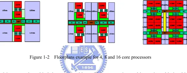
single chip. These designs have the potential to provide higher peak throughput, higher design scalability, and greater performance/power ratios than monolithic designs. However, in spite of the growing trend to put multiple cores on the chip, a deep understanding is lacking in the literature of the design space of the interconnection framework, and particularly how it interacts with the rest of the multicore architecture. For a given number of cores, the “best” interconnection architecture depends on a myriad of factors, including performance objectives, power/area budget, bandwidth requirements, technology, and even the system software.
Figure 1-2 Floorplans example for 4, 8 and 16 core processors
More cores in a chip bring more problems. First, connecting multicores in a chip is a big issue. This is because power, area, latency, and bandwidth are all first-order design constraints for on-chip interconnects. Second, the design choices for the cores, caches, and interconnection interact to a much greater degree. For example, an aggressive interconnect design consumes power and area resources that then constrains the number, size, and design of the cores and caches. Figure 1-2 shows a floorplan example for 4, 8 and 16 core processors [3]. Increasing the number of cores places conflicting demands on the interconnection – requiring higher bandwidth while decreasing available real estate. Cache size and interconnect bandwidth design exploration is a critical tradeoff of multicore SoC. Except these design choices, memory and interconnect configuration are also big design challenges. For example, cache line size is related to communication packet size which may cause the performance and
important issue of design exploration [5].
1.3 SoC Design Space Exploration
Design Space Exploration (DSE) for SoC is important to reduce cost and power while achieving computation requirements. In order to understand the cost and performance tradeoff among alternative design choices, many works have build up exploration methodology for evaluating and analyzing or predicting performance value. Here, we introduce several kinds of approaches.
Static analysis approach
This solution is often used to characterize local behavior with models to evaluate latency, energy or area. AMAT [6] is a popular model of approximate cycle evaluation for multi-level memory hierarchy system. Y. Cho et al. [7] analyzed application source code and extract memory access pattern. They built up an analysis bus model for evaluating latencies on on-chip buses. A. Muttreja et al. [8] performed micro-modeling, pre-characterizing reusable software components to construct high-level models to estimate performance and energy components to construct high-level models to estimate performance and energy consumption. Static analysis approach may combine with hardware and software models to predict the approximate cost/performance value. The property of this model is the fast analysis capability. However, this approach has lower accuracy.
Dynamic simulation approach
This approach will produce a real case simulation for specific application. Trace based simulation is always used for cache or bus architecture power and performance evaluation, sometimes will combine with analytical models for DSE. W. T. Shiue, and C. Chakrabarti [9]
used a trace-driven cache simulator and combined the AMAT model for energy and performance evaluation. T. D. Givargis et al. [10] used a cache simulator plus cache and bus analytical model for cache and bus co-design. Partial or full system simulation is also used in many works. A. Asaduzzaman et al. [11] combined cache and full simulators to explore system architecture on specific application. Simulation-based approach offers a precise and detail analysis for exploration but may need long simulation time.
Hybrid approach
Many works combined static and dynamic approach in exploration procedure. They may use some search heuristics to reduce design space. W. Fornaciari et al. [12] analyzed small benchmarks to order the design parameters by importance then simulated follow the degree of sensitivity.E. Ipek et al. [14] simulated several design point and used their models to predict the system performance and design tradeoff. T. Givargis et al. [14] analyzed dependency between design choices and reduced design space need to simulate. These hybrid approaches prune the large design choices and try to scale down simulation times.
Modern design space exploration has been proved that simulation is needed because large amount of design choices on SoC make system behavior unpredictable. Simulation provides precise and realistic performance analysis and trade-off exploration for all architectures configuration, for example, on-chip bus and memory hierarchy. However, simulation speed is the main problem that designers want to reduce. SoC designers need a fast and accurate system level simulation environment whatever how they use search heuristics for reducing simulation times. In this thesis, we will focus on system level simulation-based exploration approach. We will propose a high accuracy, high speed embedded SoC simulation methodology.
1.4 Electronic System Level Simulation Environment
Electronic System Level (ESL) design and verification is an emerging electronic design methodology that focuses on the higher abstraction level concerns first and foremost. The basic premise is to model the behavior of the entire system using a high-level language such as C, C++, or SystemC [15]. Designers raise the abstraction level of system models for different system level design stage. Figure 1-3 shows different abstraction level of modeling [16]. Node A to F represent high to low abstraction level which means fast to slow implementation and simulation speed. X-axis in the graph represents computation and y-axis represents communication abstraction model. Engineers could implement different system models at proper design stage.
Figure 1-3 System modeling graph [16]
Electronic System Level (ESL) is now an established approach in most of the world’s leading System-on-a-chip (SoC) design companies, and has been used increasingly in system design. ESL tools such as CoWare Platform Architect [17], ARM RealView MaxSim [18], Synopsys System Studio [19], etc, support designers to build up high flexibility simulation environment at different abstraction level. Engineers use these platforms for HW/SW
co-design, detail performance analysis, verification and design space exploration.
1.5 Thesis Organization
The rest of this thesis is organized as follows. Chapter 2 introduces a simulation-based simulation framework and shows its problem of simulation speed. Other speedup techniques are also described here. Chapter 3 addresses our proposed Traffic Generate (TG) based exploration framework. An integrated traffic generation flow is presented as well. Moreover, the verification of the proposed TGs’ accuracy shows in Chapter 3. Chapter 4 shows an experiment of multicore platform simulation. We will present how much speedup of our proposed solution. Finally, Chapter 5 concludes this thesis and describes the future works.
2 A
RCHITECTURE
E
XPLORATION FOR
E
MBEDDED
S
O
C
Embedded SoC are demanding high computing power and try to contain more and more computing engines in a single chip. Multicore SoC can provide a high degree of flexibility and represent the most efficient architectural solution for supporting multimedia applications, characterized by there quest for highly parallel computation. As a consequence, tools for the simulation of these systems are needed for the design stage, with the distinctive requirement of simulation speed, accuracy and capability to support designs space exploration. In this chapter, we introduce an ESL design framework which is based on SystemC as modeling language. We point out the problem of system-level simulation environment and introduce the solutions of previous works.
design process and converging towards the best-suited architectures for a target application domain. However, exploration at a very high level or at the register-transfer level is no more suited for today’s huge and complex system. This framework proposed an MPSoC architectural template and a simulation-based exploration tool, which operated at the macro-architectural level, and they demonstrated its usage on a classical MPSoC design problem, e.g. the analysis of bus-access performance with changing architectures and access profiles.
2.1.1 Full-system simulation platform
L. Benini et al. built up a multiple ARM processors simulation platform called MPARM [20]. They integrated multiple C/C++ implementations of Instruction Set Simulator (ISS) in a simulation platform and embedded those in SystemC [15] wrappers. SystemC provided a standard and well defined interface for the description of the interconnections between modules. The wrapper realized the interface and synchronization layer between ISS core model and the SystemC simulation environment. The cycle-accurate communication architecture could be connected between ISSs.
The processing modules of the system are represented by cycle accurate models of cached ARM cores. The module (Figure 2-1) is internally composed of the ARMv7 ISS model, peripherals (UART, timer, interrupt controller) and a first-level cache simulator written in C++. And the bus protocol interface was followed by AMBA or STBus protocol which active by SystemC module. Besides the processing element, AMBA/ STBus bus model and memory sub-system are all model in SystemC to build up a cycle accurate and bit accurate system. The experiment result shows simulation speed is in the range of 60000–80000 cycles/sec. The whole simulator was running on a Pentium 4, 2.26 GHz workstation. The simulation environment was all built in SystemC which has high flexibility and could be used for
different kinds of design space exploration. Next section would give an example of exploring on chip communication in MPSoC.
Figure 2-1 The SystemC-based architecture
2.1.2 On-chip interconnection and memory architecture analysis
L. Benini et al. [21] proposed a complete platform for analysis and trade-off exploration of on-chip communication architecture. They provided a case study that target on exploration under a number of different architectural configurations and two industry-standard communication infrastructures: AMBA Advanced High Performance Bus (AHB) from ARM and STBus interconnect from ST Microelectronics.
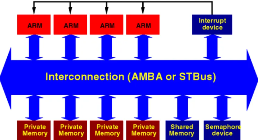
They set up the MPARM platform as Figure 2-2. It is composed of (i) four configurable 32-bit ARM processors, (ii) their private memories, (iii) a shared memory, (iv) a hardware interrupt module, (v) a hardware semaphore module, (vi) the 32-bit interconnection among them all. Interconnection can be an AMBA AHB bus or a STBus arbitrary topology, resulting in different versions of the platform. The memory devices’ access latency can be configured to
they supposed all data and instruction have been loaded in memory. The platform also provides Interrupt and semaphore devices for inter-processor communication.
Figure 2-2 The MPARM platform architecture
Figure 2-3 Simulator performance
The simulation environment provides performance profiling and analysis, including (i) statistics about processor and interconnection performance, (ii) VCD waveforms of all bus signals, and (iii) traces of memory accesses performed by every core. However, simulation accuracy and flexibility have to be traded-off with simulation speed. Figure 2-3 shows that the signal-accurate and cycle-accurate platform running a pipelined matrix multiplications. The chart depicts simulation performance with the AMBA AHB interconnect, as a function of the
number of processors and of the requested output statistics. The simulation environment was running on a Pentium 4 2.26 GHz workstation about 62000 to 86000 cycle/second for a 6- ARM platform.
Figure 2-4 Partial crossbar (a) “32” , (b) “54”
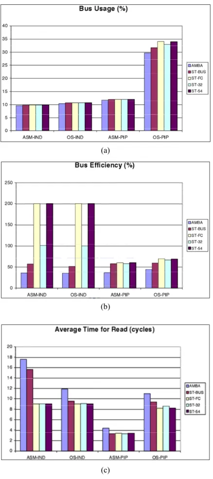
The case study focus on two types of analysis enable by the simulator. The first is a performance comparison amongst five interconnections: AMBA AHB (AMBA), STBus configured as a shared bus (ST-BUS), STBus setup as a full crossbar (ST-FC), and two additional STBus partial crossbar topologies ST-32 and ST-54 (see Figure 2-4). These interconnections will be tested with the four benchmarks: matrix multiplications performed independently by each processor (IND) and in pipeline between processors (PIP), with and without an underlying OS (ASM-IND, ASM-PIP, OS-IND, and OS-PIP respectively). All these results were measured with 8 kB ARM caches and with 1 wait state memories. The traffic analysis shows the features of benchmark and the features of two interconnect protocols and different interconnect architectures performance comparison. Figure 2-5 (a) and (b) show the bus usage and efficiency, Figure 2-5 (c) compares the average read access
(a)
(b)
(c)
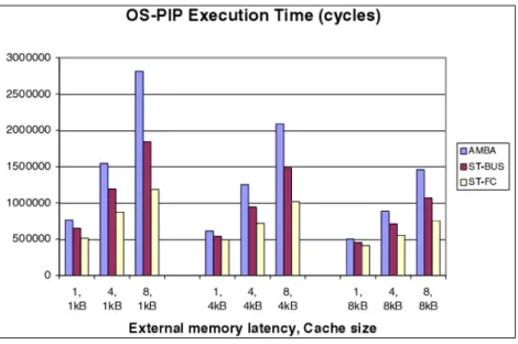
The second type of analysis is an architectural design space exploration. Based on the most meaningful benchmark (OS-PIP), they explored performance in presence of different system parameters like cache size, memory latencies and compiler optimizations. Figure 2-6 shows total execution time of the OS-PIP benchmark, in scenarios having different cache and memory access latency setting. The result shows when comparing more efficient interconnections to less efficient ones, gains are lowest when traffic is lightest. Under the same configuration of cache and memory access latency, the execution time gain of choosing one interconnection could be up to 2.1 times.
Figure 2-6 Performance of different architecture configuration
L. Benini et al. present a multicore SoC simulation environment that could be used to evaluate and explore architectures at a high level of accuracy. Same work could also be found in [5] which added AMBA AXI in case study. The MPARM ESL simulation environment proved capable of analyzing in detail similarities and differences between those architectures. However, the multicore ESL simulation environment has a critical problem: the simulation speed may not be fast enough for today’s SoC design. We will show the problem in next
2.2 Simulation Speed of ESL Simulation
In this section we well show an example to point out problems of multicore ESL simulation environment. The example platform was built on a modern ESL development tool and simulated at higher TLM modeling environment. We will first introduce the ESL tool environment and then the example platform we built and then we will show the problems.
2.2.1 ESL development tools
Figure 2-7 Coware Platform Architect-ConvergenSC [17]
CoWare Inc. CoWare Platform Architect [17] is the SystemC-based graphical environment for capturing the entire product platform and the dash board for initiating the platform analysis functions. Platform Architect speeds the concurrent design of SoCs with embedded software, enabling users to rapidly create and validate SoC designs at the
transaction level in SystemC. Together with CoWare Model Designer and the CoWare Model Library, CoWare Platform Architect enables most comprehensive system-level design solution available for SystemC. Figure 2-7 shows the graphical environment of CoWare Platform Architect.
Properties of CoWare Platform Architect are listed below.
(A) Rapid capture and configuration of hierarchical SoC platforms (B) Superior architecture and performance analysis for SystemC
(C) Rapid exploration of complex interconnect and memory architectures (D) Advanced simulation, debug, and analysis for software development (E) Automated integration of RTL blocks into the TLM system
(F) Automated creation of highly reusable, user-defined SystemC peripheral components and unit tests
(G) Standards-based SystemC TLM modeling guidelines and examples using SCML (H) Comprehensive SystemC IP model availability with the CoWare Model Library
With the property (H), Coware support model library includes a range of processor models from leading vendors such as ARM and MIPS, transaction-level bus models and RTL bus generators for common bus specifications such as AMBA, AXI, and OCP-IP, Denali MMAV memory models, and peripheral models such as the ARM PrimeCells. With the property (G), Platform Architect's native SystemC simulation environment is compatible with IEEE 1666 SystemC Language Reference Manual (LRM), Open SystemC Initiative (OSCI) transaction-level modeling (TLM) [22], and Open Core Protocol International Partnership (OCP-IP) TLM standards [23], providing support for all SystemC constructs for use by all members of a design team. Platform Architect also supports the OCSI SystemC Verification (SCV) 1.0 library extensions for transaction recording.
With the property (B) and (D), Coware Platform Architect support hardware and software profiling and analysis (see Figure 2-8). The analysis includes VCD trace dump, bus statistic analysis such as bus utilization and access latency, etc. Besides, the processors models support debuggers, for example, GDB. Designers can build up a complete SoC simulation environment composed with reused IP or user defined components in SystemC model. With the benefit of SystemC language, the environment could be simulated at different abstraction level for different design stage. In conclusion, CoWare Platform Architect supplies an ESL development environment for design exploration, verification and performance analysis. The ESL tool could bring better and faster SoC-based convergent products to market.
Figure 2-8 Coware Platform Architect analysis GUI [17]
2.2.2 ARM-based SoC platform on ESL
We build up a 4 ARM11 SoC platform on Coware environment. The platform architecture is follow by the framework in last section we introduced, MPARM. We use the Coware Model Library’s processor model: ARM1176-JZS AXI-Model. The ARM model‘s
computational abstraction support Cycle Accurate(CA) or Instruction Accurate(IA) level modeling, and ARM’s interconnection support Untimed, TLM cycle accurate and pin-accurate model. The system platform shows in Figure 1-1, we configure the ARM model as IA model and turn on the cache simulation model (which is embedded in the ARM model). The behavior of ARM IA model is in single access topology and one cycle latency for all instruction execution. The cache model has no buffers are modeled due to the instruction-accurate nature, no critical-word-first cache line loading scheme is used, and all memory accesses, line fills, and line evictions execute in a blocking fashion. The Bus Interface Unit (BIU) of ARM cores are configured at TLM Bus Cycle Accurate (TLM-BCA) level. An ARM core has 4 64-bit AXI ports, I-AXI, D-AXI, P-AXI and D-MAAXI, respectively for instruction, data, peripheral and DMA accesses.
Full Crossbar (AXI)
Private Memory Private Memory Private Memory Private Memory Shared Memory ARM 11 I Cache D Cache BIU ARM 11 I Cache D Cache BIU ARM 11 I Cache D Cache BIU ARM 11 I Cache D Cache BIU
Figure 2-9 4-ARM platform architecture
The interconnection is configured as a full crossbar with AMBA AXI protocol. One cycle latency for memory access and has one AXI port for every memory component. We use four 512х512 integer JPEG encoding as benchmarks and run on every ARM core independently. Input file streams and output file streams are all allocated in shared memory. Instruction (I)
policy.
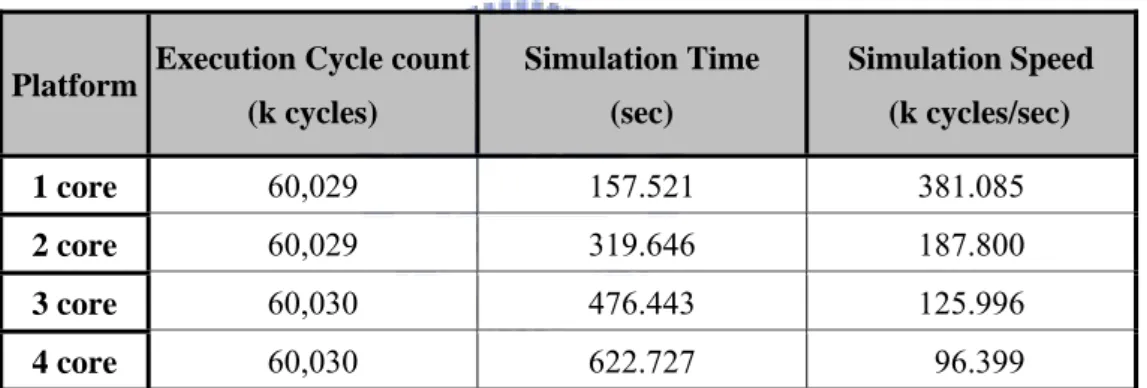
Table 2-1 shows the simulation result. We setup one to four ARM cores platform to run benchmarks independently. The execution cycle count shows no big change due to the crossbar hierarchy. However, the simulation time is much different when core number increase. The simulation speed is up to 380 k cycle/sec in 1 core platform, however, drops to 96 k cycle/sec in 4 core platform, about four times slow down. This result is same as MPARM we introduced in section 2.1. More components in a ESL simulation environment, the simulation speed drops down more quickly. As more and more processor cores would contain in SoC, the simulation speed would be a problem.
Table 2-1 Simulation result
Platform Execution Cycle count (k cycles) Simulation Time (sec) Simulation Speed (k cycles/sec) 1 core 60,029 157.521 381.085 2 core 60,029 319.646 187.800 3 core 60,030 476.443 125.996 4 core 60,030 622.727 96.399
The simulation takes 11 minutes to run JPEG benchmark. It is “OK” for one time simulation. However, designers will use ESL simulation environment for architecture exploration. During the design space exploration, simulation will be repeat and repeat. There are two run-time behaviors very difficult to model at a high level: cache behavior and network contention. Precise simulation of these two behaviors can only be done with a low-level description of the components. This means days (sometimes months) of simulation for fully search on design space.
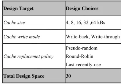
We take an example of cache configuration. Table 2-2 shows the design space example of I and D cache. The total design choices would be (30)2=900 configurations of level 1
instruction and data cache of a processor. If we consider all processors choose the same configuration in a 4-ARM platform. It would take about 155 hours for fully search on cache. If all cores have different design choices, this means (900)4 ≈ 656,100,000,000 choices for
exhausted search. The design space here does not include the interconnect network yet. In a conclusion, design exploration would take thousands (or even more) of hours for simulation. The main problem of multicore SoC ESL simulation environment is the slow simulation speed.
Table 2-2 Design space of cache
Design Target Design Choices
Cache size 4, 8, 16, 32 ,64 kBs
Cache write mode Write-back, Write-through
Cache replacemet policy
Pseudo-random Round-Robin Last-recently-use
Total Design Space 30
2.3 Related Work
Many works focus on exploration time. Here, we introduce two ways to speedup simulation. One way focuses on modeling abstraction, we will introduce in section 2.3.1. The other way focuses on completely simplifying core’s internal behavior, we will introduce in section 2.3.2.
[20][21][5] has proposed a cycle and bit accurate SystemC exploration framework. Accuracy of this simulation environment is almost closed to RTL level. The simulation speed is slow because of high accuracy. Here, we will introduce several frameworks target on speed up simulation.
Co-simulation SystemC platform
S. Boukhechem et al. [24] focused on rising up core’s abstraction level to speed up simulation. They built up their own ISSs run as a distinct UNIX processes on the host system. They connect several ISSs with SystemC communication platform models, by using Inter Process Communication (IPC). Their simulation platform has capability of co-simulating with RTL hardware model. The interconnection model is based on standard Wishbone bus [25]. This framework is much like MPARM but their ISS model does not directly embedded in SystemC wrapper. They simulation platform is faster than other cycle accurate models and RTL level simulation environment.
Programmer’s view Transaction Level Modeling
R. B. Atitallah et al. [26] proposed a framework that makes fast simulation and performance evaluation of MPSoC possible early in the design flow, thus reducing the time-to-market. In this framework, they used Transaction Level Modeling (TLM) [16] approach to raised modeling abstraction. They presented a new definition of the timed Programmer’s View (PVT) [27] level which included two complementary modeling sublevels. The first one, PVT Transaction Accurate (PVT-TA), offers a high simulation speedup factor over the Cycle Accurate Bit Accurate (CABA) [20] level modeling. The second one, PVT Event Accurate (PVT-EA), provides a better accuracy with a still acceptable speedup factor.
both communication and computation parts, as well as some abstraction of the communication infrastructure are applied. Standard PVT level does not include timing specification. Using the “top-down” design approach, they proposed PVT has timing information with two sublevels: PVT-TA and PVT-EA. Figure 2-10 summarizes their PVT framework proposal. PVT-TA operates at a relatively high abstraction level and does not take a specific communication protocol into account. This permits a rapid exploration of a large solution space by eliminating non-interesting regions from the DSE process. Solutions selected at the PVT-TA sublevel are then forwarded for a new exploration at the PVT-EA sublevel. This second sublevel specifies a precise communication protocol and takes architectural delays into account. Because estimation methodology that we developed for the PVT-EA is more accurate, it is possible at the price of less simulation speed, to locate the most efficient architecture configurations. PVT-TA and PVT-EA permit the use of PVT models in a coherent methodology, and to have accurate estimations.
framework. The cache model is not integrated in core model. Cache model is standalone and connecting to processor model with easy interface. The interconnection network of system is model in two type, read and write, and able to implement several protocols, e.g. OCP. Simulation results show PVT-TA could have 6 to 9 speedup than CABA level; PVT-EA could have 4 to 7 speedup than CABA level. Modeling effort of PVT-TA and PVT-EA is about 34.6% and 26.4% of CABA.
Exploration at CCATB abstraction
S. Pasricha et al. [28] proposed a new TLM modeling abstraction called (Cycle Count Accurate at Transaction Boundaries) (CCATB) for on-chip communication space exploration. The abstraction level allows faster system prototyping and, more importantly, better simulation performance, while maintaining cycle count accuracy. CCATB models yield an average performance speedup of 120% over PA-BCA (Pin-Accurate Bus Cycle Accurate) and 67% over T-BCA (Transaction-based Bus Cycle Accurate) models.
CCATB includes read and write operation for a transaction. Transactions at the CCATB level are similar to transaction at the TLM level [29] except that the transaction modeling, in addition, passes bus protocol-specific control and timing information. Unlike PA-BCA and T-BCA models, they do not maintain accuracy at every cycle boundary. Instead, they raise the modeling abstraction and maintain cycle count accuracy at transaction boundaries. They also use ISS as core model and implement in CCATB wrapper. The experiment result shows the CCATB could have same cycle count value as T-BCA and PA-BCA. Most of important, CCATB has better simulation performance than PA-BCA and T-BCA. In a summary, CCATB offers a new cycle accurate abstraction level by sacrificing visibility of signals at every cycle boundary and give user a faster interconnection modeling. This framework is like PVT framework; both of them focus on communication modeling.
In a summary, TLM- based simulation is operated at higher abstraction to raise the simulation speed by sacrifice some fidelity. TLM models focus on communication behavior abstraction and less care about computation abstraction. During the design flow, design space can be narrowed down by applying higher abstracted TLM-based exploration first then using lower abstraction modeling for exact performance estimation. Cycle-accurate exploration is still required to determine the best design choice. Many works have discussed about TLM modeling, they have proved that TLM simulation technology do help to speedup design space exploration.
2.3.2 Traffic generator
Traffic Generators (TGs) are more and more used during SoC design for platform prototyping or performance evaluation. When using TGs, simulation time is decreased because the IP is not fully simulated. Simulation is also more flexible. The idea of using TG is illustrated in Figure 2-11.
On-Chip Bus
Core Core Core
Peripheral Memory
ESL Simulation Environment
SW SW SW
BIU BIU BIU
On-Chip Bus
TG TG TG
Peripheral Memory
ESL Simulation Environment
Figure 2-11 Simulation environment with core/TG model
accurate models of the alternative interconnects only. While the internal processing of IP cores does not need thorough replication by the generators and can often be modeled by waiting for an amount of cycles between network transactions. In this section, we will introduce several traffic generators using on ESL simulation environment in previous work.
Statistical traffic generator
G. Strano et al. [30] built a multi-abstraction and accurate virtual platform allowing an in-depth investigation of the behavior of system components, captured in isolation and when inter-operating with each other in a complete MPSoC platform of industrial relevance. The whole MPSoC simulation platform was modeled and simulated with clock-cycle accuracy and a SystemC-based virtual platform [21] which was used as the backbone environment (section 2.1). In order to speed up the analysis, functional traffic generated by the most critical audio and video IP cores was reproduced by means of configurable traffic generators (IPTGs).
IPTG is a SystemC module developed by STMicroelectronics aimed at reproducing the communication behavior of a generic IP. In its simplest configuration, IPTG can generate bus traffic which obeys some statistical properties, e.g. in terms of burst length, transaction types, addressing schemes, or it can also issue a transaction according to a specified sequence. However, IPTG is best used to emulate the behavior of complex real-life IPs: such IPs can be often seen as having a number of internal sub-process (or agents), each one with its own characteristics (buffering space, transaction pipeline capability) but in some way dependent on each other (e.g. when operating in pipeline). With IPTG, each agent traffic is handled automatically according to its characteristics, and inter agent synchronization points can be set to emulate dependencies between them. Once instantiated in a platform, IPTGs will generate bus transactions at different abstraction levels (transaction-level, bus cycle-accurate) according to what is specified in a per-IP configuration file, where all the required options and
parameters are set. IPTG turn out to be a powerful and handy tool to the system integrator, as it allows to try out the SoC communication infrastructure in real-life conditions such as heavy-loaded transients which are not likely to be reproduced using random packet injection.
The IPTG has a great property of supporting multi-abstraction bus transaction. This is good for designers to simulate system with high flexibility. However, the IPTG’s bus interface unit can only support STBus and rely on other bridges to connect to interconnect of other protocols. Another problem of IPTG is the traffic generated by IPTG obeys with statistical properties but not real case of application in IP core. The configuration inside of the core, such as cache size configuration, can not be emulated by TG.. That will be a critical problem of design space exploration.
Stochastic traffic generator
T. Risset et al. [31] used stochastic models for traffic generation. They presented an automatic detection of traffic phases by analyzing simulation traces and have proved that these phases are necessary to emulate the traffic generated by multi-media applications running on SoC. They used their TG to replace an IP an cycle-accurate NoC performance evaluation.
This work focused on an automatic phase of analyzing applications’ property and generated stochastic traffic. First, they generated a reference trace by simulating the processor IP. This trace is obtained with an ideal network environment (no network contention), which makes the simulation very fast. Then, they processed the trace in a traffic analysis and synthesis tool to obtain configuration files for traffic generators. They validate the TG in a SystemC-based cycle-accurate and bi-accurate simulation environment: SocLib [32]. The TG does not support any interconnect protocols and does not support multi-abstraction bus
shows in Figure 2-12. The TGs’ transaction behavior is all model in time parameters, e.g. A(k). This means the transaction interface does not model the real interconnect behavior of IPs. This is a problem of real system simulation. The TG models would need user defined transferring bridges to connect with the interconnection network in the target simulation environment. This would cause the behaviors different form real IP core models on simulation.
Figure 2-12 Traffic modeling formalism
Deterministic traffic generator
Table 2-3 TG instruction set
Deterministic traffic generators are derived from real simulation traces or written from scratch by IP designers. Such TGs can generate accurate transactions in time, size, and idle time that match the behavior of an IP. S. Mahadevan et al. [33] proposed a TG implementation as a very simple instruction set processor. They emulate TG as an OCP master.
This TG is able to issue conditional sequences of traces composed of communication transactions separated by idle/wait-periods. To evaluate the TG concept, they have integrated the TG model into MPARM platform. On the platform, the OCP interface modules were adapted to collect traces of OCP request and response communication events into a predefined file format. The address and data fields of the transactions are also observed. Trace entries are single or burst read/write transactions. Table 2-3 shows the OCP-master TG instruction format to recode the traffic format. Figure 2-13 shows the example trace file extracted from MPARM (a) and the trace file fed to TG (b).
Figure 2-13 Example trace file (a) MPARM trace (b) TG program
Deterministic TG could strongly perform to replay the real master traffic behavior. However, the accurate traffic is extract from full system simulation, this means the traffic needs to re-simulate if the core configuration is changed, e.g. cache configuration. This is an
strong ability to perform inter active behavior between cores. However, most of the traffic is the behavior to access memories or other slave components. Traffic file size might be a huge loading for simulation. Overhead of reading trace file would be more critical for this “processor-like” traffic generator.
Traffic generators do speedup simulation time because it simplifies cores’ computation behavior, but the behavior might be different from real core model. Traffic generated from statistic or analytical solution may not represent the real application running on the platform. SystemC wrapper of traffic generator is also an important issue that may derive the transaction behavior. There are three important issues that we have found to be improved. First, the interface of TG must support multiple abstraction level, flexible interconnect protocols choices and other configurable parameters. Second, the behavior inside of traffic generator model should not have too much overhead, e.g. file parser. Third, the overhead of traffic file generation should not take too much effort. There should be a fast and automatic tool for traffic file generation that supports configurable core parameters and application change. Next chapter we will describe a TG-based simulation framework we proposed, including of traffic file generation, TG models and traffic file format.
3 P
ROPOSED
E
XPLORATION
M
ETHOD
SoC exploration always takes time for simulation. Here, we proposed an exploration framework which keeps those benefits in previous works, MPARM, but speedup the exploration time on our simulation platform. Our method allows real application’s performance analysis and trade-off exploration of on-chip communication architectures. We will introduce our proposed Traffic Generator-based exploration framework in this chapter.
3.1 Proposed Exploration Design Space
The design issues we care about are memory organization and on-chip bus architecture which are the same as the previous work, MPARM. Here, the system architecture is like Figure 3-1. We focus on ARM1176-JZS and ARM1136-JZS processor as the target processors. These two cores have same behavior of instruction modeling but have different supported bus interface. ARM1136-JZS support AHB interface and has five ports, IAHB,
since they are not often used. The IAHB is used for instruction read access only; RAHB is for data read access and WAHB for write access. ARM1176-JZS supports AXI interface and has four ports, IAXI, DAXI, DMAAXI and PAXI. We will not discuss PAXI and DMAAXI here. The IAXI is used for instruction read access only. DAXI is for both read and write data access, since AXI protocol interface has four channels, including read/write address, write data channel, read data channel and write response channel. Caches could also be configured by designers, e.g. I and D cache size.
Figure 3-1 Multicore system architecture
We focus on AMBA 2.0 and 3.0 interconnection protocols. The network architecture could be shared bus, multi-layer bus, crossbar and else. Bus arbitration, register slicing and bus width are also changeable. Memory model is also configurable in protocols, size, access latency and access width. Peripheral IPs including VIC, timer, memory controller and other Primecell IPs are available in Coware’s tools. The system flexibility is high. We list those design choices in Table 3-1. Our simulation environment must support these design choices configuration.
Table 3-1 Proposed exploration design space
Explored Target Design Parameter Design Choices
Core
Core number 1, 2, 3, 4
Target processor ARM1176
ARM1136
Cache Configuration
Cache size 0, 4, 8, 16, 32 ,64, 128 kBs
Cache line size 4, 8, 16, 32, 64, 128 Bytes
Set associativyty 1, 2, 4, 8, 16 ways
Write data coherent mode Write-back
Write-through Replacement policy Pseudo-random Round-Robin Last-recently-use
Interconnect
Architecture
Protocol AMBA 2.0 AHB
AMBA 3.0 AXI
Interconnect network
Single shared bus Multi-layer bus Crossbar
Bandwidth 32, 64 bits
Bus arbition Round-Robin
Fixed arbitration
Memory Configuration
Memory access latency 1, 2, 4, 8, 16, 32 cycles3.2 Proposed Traffic Generator Based Exploration Method
We have introduced several simulation frameworks in section 2-3. Now, we are going to deal with the slow simulation speed problem and use Traffic Generators to replace the core models. Here, in this section we will introduce how we use traffic generators for exploration.
3.2.1 Proposed TG-based exploration method
Section 2.3.2 describes several works that use traffic generators to replace core models. However, there are two problems to use traffic generators. First, we must emulate processor’s communication behavior as the original behavior. Second, we must avoid too much overhead of traffic generation. Traditional traffic generator may use replay technique, e.g. Deterministic TG (section 2.3.2), to make the TG behave the real transaction behavior of real application. However, the traffic pattern needs to be generated from full system simulation. This approach is not suit for our design space because we focus on memory organization and on-chip bus architecture. When these design choices are changed, traffic file need to be re-generated by repeated full system simulation. In order to deal with this problem, we propose a traffic generator to deal with this problem.
Figure 3-2 Proposed traffic generator
Figure 3-2 shows the idea of our TG. The original processor model consists of three parts, ISS, cache and bus interface unit. These three behaviors let the core behave like a real hardware. However, we are now going to use this system level simulation environment for design exploration. During the exploration steps, designers must run the simulation repeat and repeat for our proposed design space, interconnect network and memory organization. Core’s
computation behavior is always no change, or even don’t need to care about that. The most important is transaction behavior must be the same for interconnection design exploration. So, the cores’ ISS behaviors are no need to real simulate on the platform. Here, our approach is to record the memory accesses that generated from ISS and keeps the cache and BIU in TG model. This is because ISS always behave the same memory accesses while repeated simulation. Our TG model only need to replay the access behaviors between cache and BIU while exploration. Besides, if the design choices of cache are few, we can record the memory access patterns produced form cache model and extract both cache and ISS models from the TG model. Following with this idea, we propose our exploration flow in Figure 3-8. The first step is to off-line generate from cores’ internal behavior. Then, we load the traffic file into the TG model in our ESL simulation environment and start the exploration. The simulation will be repeated and repeated generating performance values of different architectures. The traffic file needs to be re-generated only when we off-line simulate cache model behavior. We will introduce the details in the following sections.
3.2.2 Off-line traffic generation
In this section, we will introduce our traffic generation method and the traffic file format we use.
Proposed traffic generation method
Figure 3-4 Off-line traffic generation of proposed TG-1
Here, we propose two ways to off-line generate traffic file. The first one is called “TG-1”, shows in Figure 3-4. We separate the simulation framework in two steps. First, we off-lined simulate cores’ ISS behavior. We use RVDS 3.0 ARM ISS [34] model as the core simulator, since we focus on ARM 11. In this step, we will run the target application source code on the ARM11 instruction accurate simulator to extract memory access patterns. These patterns include instruction accesses, read data accesses and write data accesses. These patterns will not change since the cores’ behaviors are always same for specific source codes. This means the off-line simulation only need once and needs to re-simulate in exploration. The second step is to translate the memory access pattern to our proposed traffic file format. The traffic file consists of information including access type, access address, write data, access packet size and timing information. Here, the timing information represents the execution pipeline
latency. Since the target ARM 11 model of Coware Model Library set all instructions execute one cycle. So, the default instruction latency is 1. We keep our traffic file generator to be configurable. Users could set different timing information value for different target processors’ ISS or even the cycle accurate core models. These values will be recorded in traffic file, which could runtime control TG‘s behavior. We will introduce traffic file format in next section.
Figure 3-5 Off-line traffic generation of proposed TG-2
The second approach of off-line simulation, as Figure 3-5, is called “TG-2”. We first run the target application source code on the instruction accurate simulator to extract memory access pattern. These patterns include instruction accesses, read data accesses and write data accesses. Then we will use an off-line cache model to simulate the cache behavior for different configuration. This cache model’s design space shows in section 3.1. The off-line traffic generator will produce traffic file for TG which has information including access type, access address, write data, access packet size and timing information. The traffic file format is the same as “TG-1”. Here, the timing information represents the relative latency between two transactions. The instruction latency is one cycle latency in ISS model, and we record this
pattern that we feed in cache model is equal to previous wok which means the ISS still need only one time simulation. The overhead of this framework is that we need to re-simulation cache model for different cache configuration. However, the cache model is implemented in C/C++ language and no other interconnection behavior. The off-line cache model simulation is fast. The cache model running on Pentiun 4 dual core 3.4 GHz PC only need for few seconds. We can easily ignore this overhead in our simulation framework. Also, the benefit of off-line cache model is the small traffic size. Cache could help to reduce transfer on system interconnect and reduce system simulation loading.
Proposed traffic format
Figure 3-6 Purposed traffic timing diagram
Figure 3-6 shows the timing diagram of our proposed traffic file format. First diagram represent the real situation of transaction behavior. Tx represent the transaction cycles count.
Here, we define the transaction behavior starts from BIU request trigger until TG receives response signal. τx represent the cycles count that no transaction happen. Core could be
executing or idling during these cycles. If we can model the BIU to behavior correct, the Tx
and T’x should be equal. However, the cores’ computation behavior is decides by the off-line
simulator. If we do not model the latency of cores’ computation, the timing diagram would be like the middle one in Figure 3-6, traffic with no relative time. Since we have claim that our off-line model could record timing information in traffic file, our TGs’ timing diagram would be like third diagram in Figure 3-6, traffic with relative time. Ideally, the traffic with relative time should have same behavior of real situation as follow
Tx = T’’x
τ
x =τ
’’xThe fist equation is decided by BIU’s accuracy, the second one is refer to our off-line simulator. Ideally, these equalizations are met because we have recorded time information in traffic file and the time value is equal to core’s ISS model.
of traffic file. A traffic access pattern includes relative cycle count, access type, burst size, address and data. Figure 3-7 (b) shows the binary traffic file format. The off-line traffic file generator will generate binary format traffic file.
Table 3-2 Traffic format
Access Information Binary Size (Bytes) Parameter
Relative time (
τ)
2 0~65535Type 1
I – Instruction access R – Read data access W– Write data access Q– TG idle
Burst size 1 1, 2, 4, 8, 16, 32
Address 4 32-bit hexadecimal value
Data 4 32-bit hexadecimal value
Table 3-2 lists the information including parameters and encoding binary size. An access command requires 11 bytes. Relative time requires 2 bytes, and highest cycle count is 65535. The traffic generator would automatic insert idle command if the relative time exceeds this number. “Type” refers to different access command. “Q-type” is the idle command which makes TG stall for
τ
cycles. “Burst size” is the option for indicate the burst transaction size. The transfer unit of the burst size is 4 bytes. The data is also 4-byte length. This means that when a command’s burst size is more than 1, the next (burst size -1) commands and itself would be packet to one burst transaction. For example, in Figure 3-7 (a) the third command is as flow:This command is a write data access for 4 burst data, and the address is “0x21000”, data is “0x0”. TG will packet the next three commands to one burst transfer. The burst data would be 128-bit length. TG’s BIU will automatically change the burst transaction type follow the bus protocol, e.g. “WRAP” or “INCR”.
3.2.3 Full system simulation
In this section, we will introduce in thee part, our ESL simulation environment, the runtime behavior of TG model and the statistical capability of our TG model.
ESL simulation environment
We use CoWare Platform Architect as the ESL platform development tool (section 2.2.1). The CoWare Model Library supply IP and bus models help us to build up a flexible system. We can build models by SystemC language in user-defined abstraction. Since Coware support multiple protocol libraries it could help users to set up the model in OCP, AMBA 2.0 and AMBA 3.0 interconnect protocol with APIs. All of the protocols available in these libraries can be used at the PV (Programmer’s View which is equal to Untimed TLM), TLM, or pin-accurate abstraction level. Besides, the analysis tool in Coware provides textual and graphical views for both the hardware engineer and software developer to analyze items’ critical to System-on-Chip architecture and software performance. We use these functionalities in our ESL simulation platform, so our platform kept those properties and even have much more flexibility then the framework we discuss in last section.
We build the simulation platform as Figure 3-8. We model the TG module in SystemC language which is able to use for different architecture. TG module is configurable for all design space we list in section 3.1 and is a parameterized model. Users can set configuration
Platform Architect GUI design platform. The BIU’s interconnect protocols and port widths are also settable on the platform. Also, we model the BIU to support multi-abstraction level. This makes our platform to have more flexibility for exploration. The traffic files source, statistical capability and cache on/off all are set on the ESL tool. This is convenient for users change the system architectures. The TG model for TG-1 and TG-2 is the same. We need to set the TG model to be cache off for TG-2 solution as Figure 3-9. SystemC is an event-driven modeling language. The simulation speed will improve since we turn off the cache’s behavior modeling.
Figure 3-8 ESL simulation platform of proposed TG-1
Figure 3-9 ESL simulation platform of proposed TG-2
Runtime behavior of TG TG-1 behavior flow Start Finish Wait Parser Idle Cache beh. Transac tion Hit Miss
Figure 3-10 Proposed TG-1 behavior flow
Figure 3-10 shows the behavior of TG-1. Our proposed TG including three parts of model, file reader, cache model and bus interface unit (BIU). File reader will first read the access information of traffic file including timing information, access type, burst size, address and data. Simulation starts when an input start signal trigger. The parser will then identify the access type to control instruction or data cache’s behavior. Here, the cache model will not have pipeline latency property since the ARM ISS of Coware Model Library does not behave pipeline cycles. Cache model decides if the access is hit or miss in cache memory. If the access is hit, TG will return to parser state to get next access and record the timing information. The time value will be recorded and accumulated until the cache access is missing. When cache miss happens, TG will turn to an idle state. The TG will stall for several
will not stall for every access. After stall for recorded cycles, this time value will be reset to zero then jump to transaction state. TG will trigger the BIU to start access. There is a FIFO in BIU, TG will feed the instruction or data access into the command FIFO. The access would be cache lines fill in, or cache lines write back or data write through. The information in FIFO includes access type (I/R/W), burst size, address and data. BIU itself will start transaction behavior in FIFO. The BIU here we proposed does not support interleaving transaction (also called outstanding transfer) only one transfer for one time traffic access behavior since the ISS model does not support outstanding transfer. TG’s BIU has same ports as the ARM11 model. BIU will identify which to port to send transfer request. After transaction finish, the TG will return to parser sate to get next traffic access if the transaction finish. The TG’s behavior will stop until the last traffic access.
Figure 3-11 Proposed TG-2 behavior flow
When we use “TG-2” solution to generate traffic file, the TG model in the simulation environment includes two parts of model, file reader and bus interface unit (BIU). File reader will first read the access information of traffic file including timing information, access
type, burst size, address and data. Figure 3-11 shows the TG runtime behavior. Simulation starts when an input start signal trigger. The parser will then jump to idle step and stall for multiple cycles recorded in our traffic file. The BIU behavior is the same as TG-1. TG will return to parser state to keep access next transaction. The TG-2 simulation speed will be fast than TG-1 because there is no cache model simulation and smaller size traffic file.
Proposed TG’s statistical capability
Coware’s analysis tools support interconnection analysis and profiling. However, the core’s analysis capability is based on the models’ support. ARM’s ISS model does support users to trace with debugger tool, cache model does too. Our proposed traffic generator obviously not support trace behavior because no real computation in the system. So, our TG focuses on cache behavior and transaction modeling. Many trace-based cache simulators are available today, e.g. Dinero [35], MSCSim [36]. These cache models have high flexibility and support statistics. However, these models may not suit for embedding in SystemC wrapper because the complicated source code. Here we build up our simple cache model which support all design space we target on. Our cache model support cache analysis which is based on those popular cache models. The cache analysis includes access times, hit times, miss times and miss rate. Also, the detail analysis including compulsory/capacity/conflict miss times are support. Our on-line or off-line cache model both support these analysis capabilities and can be turned on/off by users.
Transaction analysis capability is embedded in TG’s BIU. The statistic includes average read/write access latency, total access times and total idle time. This information could help users to get some referenced performance value, e.g. CPI and efficiency. TG itself also has a timer inside. Timer would record timing when the TG starts its behavior until the end of
capabilities can be control by users. These behaviors would slow down simulation, however, not a critical part. Co-operating with the analysis tool on interconnect network, our proposed simulation environment does help user to explore architectures as the exploration framework in chapter 2. The only one capability not supported in our environment is the software verification, however it is not important when architectures’ exploration. Our proposed exploration framework offers a complete analysis tools for designers.
3.2.4 Analysis of two proposed TG
We propose two traffic generators TG-1 and TG-2. These TGs both have high simulation speed than ARM model. But these TGs have there own properties. Here, we will introduce their properties and show what situation the TG suit for.
TG-1’s benefits list as follow:
(A) Higher accuracy
(B) Runtime configurable cache model (C) Only one time off-line simulation
The TG-1 has a property of higher accuracy because the cache is embedded in on-line TG model. The interactive behavior between cache and BIU is much more closed to real case. Also the latency on the TG has more accuracy than off-line simulation. The second benefit is the cache model could change configuration with other interconnect architecture at the same time. It is convenient for designers to change platform at ESL simulation environment. The third benefit is the main idea of our proposed TG. Core’s computation behavior does not need to re-simulate every time we change the architecture. Off-line traffic generation procedure only needs to operate one time, since all configurations are settable at runtime. Though, the off-line simulation may need couple minutes, which is refer to application’s behavior, the
![Figure 1-1 Product function/chip and industry average “Moore’s Law” trends [1]](https://thumb-ap.123doks.com/thumbv2/9libinfo/8430330.181135/18.892.235.709.216.527/figure-product-function-chip-industry-average-moore-trends.webp)
![Figure 2-7 Coware Platform Architect-ConvergenSC [17]](https://thumb-ap.123doks.com/thumbv2/9libinfo/8430330.181135/32.892.167.770.445.911/figure-coware-platform-architect-convergensc.webp)
![Figure 2-8 Coware Platform Architect analysis GUI [17]](https://thumb-ap.123doks.com/thumbv2/9libinfo/8430330.181135/34.892.130.840.544.878/figure-coware-platform-architect-analysis-gui.webp)