GaN-based microcavity polariton light emitting diodes
Tien-Chang Lu*
a, Ying-Yu Lai
a, Si-Wei Huang
a, Jun-Rong Chen
a, Yung-Chi Wu
a, Shiang-Chi Lin
a,
Shing-Chung Wang
a, and Yoshihisa Yamamoto
ba
Department of Photonics, National Chiao Tung University, Hsinchu 300, Taiwan
b
E. L. Ginzton Laboratory, Stanford University, Stanford California 94305, United States
ABSTRACT
Here we report the first realization of a current injection microcavity GaN exciton-polariton light emitting diode (LED) operating under room temperature (RT). The hybrid microcavity structure consists of InGaN/GaN quantum wells sandwiched between bottom epitaxial DBR and top dielectric DBR. The anti-crossing behavior of polariton LED denotes a clear signature of the strong interaction between excitons and cavity photons.
Keywords: GaN, exciton-polariton, light emitting diode (LED), Rabi splitting,
1. INTRODUCTION
Recently, exciton-polaritons, the half-light/half-matter quasi particles generated from strong coupling between excitons and microcavity photons in semiconductor high-Q microcavities (MCs) have attracted much attention due to their potential to probe fundamental physics and create practical devices [1]. Due to their bosnic nature, exciton-polaritons with very small effective mass (10-8 that of hydrogen atom) increasing the critical temperature of condensation to
cryogenic or even RT. On the other hand, the excitonic nature enables polaritons to interact with phonons, excitons, or polaritons and relax to their final state. The above mentioned properties have led to demonstration of various experimental results, including solid state Bose Einstein condensates (BEC) or ultra-low threshold polariton lasers [2-8], and polariton parametric oscillator [9]. However, most of the reports on polariton are based on optical pumping at room temperature (RT) or electrical-driven at low-temperature, which are not consider for practical usage.
To achieve a practical polaritonic device, the exciton-polariton emitters should be driven in electrical way at RT. For electrical driven aspect, the electrically excited microcavity polariton emitter had been demonstrated in organic semiconductors and a GaAs/AlGaAs quantum cascade structure previously [10, 11]. Due to the lattice-matched substrate and mature epitaxial technology, electrically pumped polariton LEDs have been demonstrated in commonly used GaAs based multiple quantum wells (MQWs) system at temperature from 10K to 315 K [12-15]. Although RT polariton LED is realized in GaAs system[13], they still suffers from small exciton binding energy and oscillator strength, from this point of view, wide bandgap materials with larger exciton binding energy and oscillator strength provide more a reliable RT operation for practical polariton devices. So far the RT polariton emission and lasing are already demonstrated in several wide bandgap material systems, including GaN and ZnO [7, 8, 16, 17, 20, 21] under optical pumping. The current injection wide bandgap semiconductor polariton emitters such as LED or laser are still obscene. The main advantages of strongly coupled GaN microcavity polariton LED compared to other non-wide bandgap material systems are larger exciton binding energy (40 meV for quantum well), fast phonon-assisted relaxation rate, and large oscillator strength. Thus the hot exciton-polaritons in GaN polariton LED could be thermalized efficiently with large Rabi splitting and fast Rabi oscillation frequency [18, 19]. The fast Rabi oscillation between quantum well (QW) excitons and cavity photons in the exciton-polariton LED suppress the inhomogeneous broadening induced from exciton localization in the InGaN well and the nonradiative decay in normal weakly coupled LED structure.
2. ELECTRICALLY PUMPED GAN-BASED EXCITON-POLARITON LED
2.1 Sample fabrication
The hybrid microcavity structure of an electrically pumped III-N based exciton-polariton LED was achieved by a bottom epitaxial DBR [22] and a top dielectric DBR. Figure 1a shows the hybrid microcavity structure of exciton-polariton LED. The 5λ-thick cavity layer composed of an n-type GaN, 10-pair In0.15Ga0.85N/GaN MQWs, and a p-type GaN layer. The
InGaN/GaN MQWs are inserted at the antinode of the optical field to enhance the coupling between the QW excitons and the MC photons as shown in Figure 1b. In order to achieve the strong coupling regime in the hybrid microcavity, we firstly focus on the high crystal quality and high reflectivity epitaxial DBR. By inserting superlattice (SL) into bottom epitaxial DBR, the tensile strain between the AlN and GaN is sufficiently suppressed [22]. The grown crake-free 29-pair AlN/GaN bottom DBR exhibits a reflectivity of R = 99.4% with a spectral bandwidth of 25 nm. The current injection area is confined by the SiNx dielectric layer with a 30 μm light emitting aperture. The transparent contact layer is formed
by a 30 nm thick indium tin-oxide (ITO) layer. We then annealed the ITO at 525°C under the nitrogen ambient to reduce the contact resistance and absorption of the ITO layer. After that, the coplanar metal contact was deposited by the electron gun evaporation. Finally, the high reflectivity dielectric top DBR was formed by 8-pair Ta2O5/SiO2 alternative
λ/4 layers, with a high reflectivity of R = 99% and wide stop bandwitdth about 80nm. Figure 1c shows the scanning electron microscopy (SEM) image of the processed electrically pumped microcavity LED structure.
Figure 1. Schematic sketch of the electrically pumped InGaN-based polariton LED. (a) The GaN-based hybrid microcavity consists of a 29-pair AlN/GaN bottom DBR and a 5λ optical thickness microcavity composed of a n-type GaN, 10 pairs In0.15Ga0.85N/GaN MQWs, a p-type GaN layer, an ITO layer and an 8-pair Ta2O5/SiO2 top
DBR. (b) Optical intensity field and refractive index distribution along the vertical structure. (c) SEM image for the processed polariton LED structure.
2.2 Measurement results
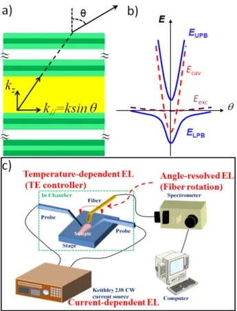
In the strong light-matter coupling regime, the cavity photons and QW excitons form a composite quantum system with two new eigenstates, upper polariton branch (UPB) and lower polariton branch (LPB), which exhibit two distinct peaks at electroluminescence spectrum. We then used three commonly experimental techniques to observe the dispersion curves of exciton-polariton in the GaN microcavity LED. The first one and second one is the temperature-dependent electroluminescence and angle-resolved electroluminescence (AREL) [23, 24]. The former technique mainly relies on the different temperature-dependent variation tendency between QW exciton energy and the cavity photon energy. The latter technique relies on the one-to-one correspondence between each internal LP at k// and each external photon emitted
increasing emission angle as well as the detuning parameter between the cavity photon and the QW exciton. The third technique is current-dependent EL, which could specify the screening of strong coupling regime through increasing injection current. The above mentioned three types of measurement could be performed in a normally used temperature-controlled EL system as shown in Figure 2c.
Figure 2. (a) Schematic sketch of one-to-one correspondence between internal exciton-polariton and external photon. (b) Schematic sketch of angle-resolved exciton-polariton dispersion curve. (c) Combined system of three types of EL measurements.
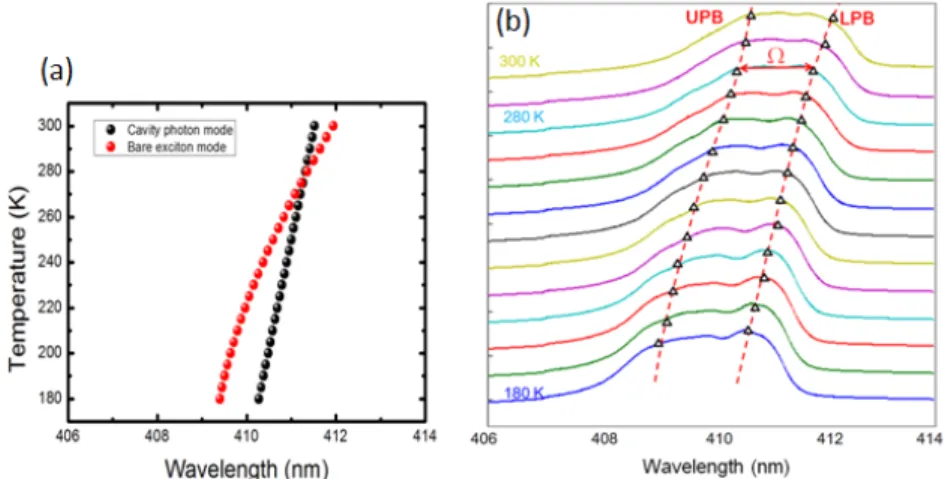
From above mentioned measurement methods, the photon-exciton detuning mechanism of the temperature-dependent EL is based on the different red-shift tendency of cavity photon mode and bared exciton mode as the operating temperature increasing. Figure 3a shows numerical simulation result of the cavity photon mode and bared exciton mode versus temperature. The red-shift of the cavity photon energy with increasing temperature is estimated to be ∼0.054 meV/K [25] due to the temperature dependent refractive index. On the other hand, the QW excitons energy depicts a steeper decreasing tendency which follows the modified Varshni formula including the localization effect:
E T
( )
=
E
m(0)
−
⎣
⎡
(
α
T
2) / (
T
+
β
)
⎤ ⎡
⎦ ⎣
−
(
σ
2) / (
k T
B)
⎤
⎦
(1) where E(T) is the emission energy at T, Em(0) is the energy gap at 0 K, α and β are Varshni’s fitting parameters, kB is theBoltzmann constant, and σ is related with localization effect [26]. After prediction from above simulation, the EL measurement was then performed in a temperature-controlled, closed-cycle, liquid nitrogen cryostat. Figure 3b shows temperature dependent EL spectra from polariton LED collected from the fiber at zero degree with 2mA driven current. The distinguishable emission peaks in spectrum denotes the upper polariton branch (UPB) and lower polariton branch (LPB). As operation temperature increased, the red shift the QW exciton energy resulted from a reduction of the bandgap energy, overwhelms the decrease in the cavity photon energy due to the temperature-dependent refractive index. The dispersion curves of exciton-polariton (red dash) which is fitted with the parameters in Figure 3a shows a
good consistency with the EL spectrum. From the simulated dispersion curves, the corresponding normal mode splitting (Ω) at zero detuning is about 6 meV at a temperature of 280 K.
Figure 3. (a) Experimentally measured temperature-dependent electroluminescence spectra from 180 to 300 K with 2 mA injection current. (b) Temperature-dependent EL spectrum together with the fitted polariton dispersion curves.
For the angle-resolved electroluminescence measurements, the operation temperature was kept at 180 K with 2 mA injection current. Figure 4a shows the measured angle-resolved electroluminescence spectra, which reveals the clearly seen upper and lower polariton modes at a slightly negative detuning. In Figure 4a the broadened spectra at large angle is due to the limitation of the collection efficiency of the optical fiber. Figure 4b shows the color map of the ARPL spectrum with the fitted polariton dispersion curve (white dash). A clearly seen anti-crossing behavior exhibits the evidence of the strong coupling regime. The corresponding normal mode splitting is about 7meV at 7.4° collection angle, and is very close to that obtained from the temperature-dependent experiment at 280 K. The value of normal mode splitting is smaller than the previously reported GaN/AlGaN MQWs MC by optical pumping experiment, which may be attributed to the longer cavity length, fewer MQWs number or weak optical field overlap with MQWs [16]. The poor p-type conductivity of AlGaN layers induces the difficulty on the electrical injection to the GaN/AlGaN MQWs. Our InGaN/GaN is still the better choice for the electrically driven polariton devices since the good conductivity of p-type GaN is easy to achieve.
Figure 4. (a) Measured ARPL spectra of exciton-polariton LED. (b) Color map of the measured polariton angular dispersion curves with a Rabi splitting (Ω) of 7 meV is observed at 7.4°
To further verify the strong coupling effect in the polariton LED, we employed the current-dependent electroluminescence spectra at zero degree of the angle and under the temperature of 240 K when the detuning was closed to the zero. From Figure 5, the normal mode splitting progressively decreased as injection current increases from 0.5 to 4mA, which could due to the dephasing of the polaritons caused by the stronger exciton-exciton scattering as polariton population increased. Then the enhanced exciton-exciton scattering would dominate the bleaching the strong coupling regime in the MC. With further increased injection current after 4mA, the device was damaged by the heat dissipation problem. For the other hand, the integrated electroluminescence intensities for both UPB and LPB show a linear increase trend with the injection current, which could be due to the fast Rabi oscillation between cavity photons and excitons that suppresses the possibility of energy loss through the nonradiative decay channel in the normal weakly coupled LED structure [14, 15].
Figure 5. The peak energy of polariton emission as a function of injection current from 0.5 to 4 mA at 240 K.
3. CONCLUSION
I
n conclusion, the RT electrically driven polariton LED was demonstrated in III-nitride based MC. The evidence of strong coupling regime in MC is confirmed by the anticrossing behavior in both temperature-dependent and angle-resolved electroluminescence spectra. The demonstration of an electrically pumped III-nitride based polariton LED atroom temperature could open a new way for the realization of various practical polaritonic devices including high efficient UV polariton LEDs and ultra-low threshold polariton laser.
ACKNOWLEDGMENTS
The authors would like to gratefully acknowledge C. K. Chen, S. W. Chen, Z. Y. Li, and Prof. H. C. Kuo at National Chiao Tung University for technical support. This work has been supported in part by the MOE ATU program and in part by the National Science Council of Taiwan under Contracts NSC99-2221-E-009-035-MY3, NSC99-2120-M-009-007, and NSC98-2923-E-009-001-MY3.
REFERENCES
[1] Weisbuch, C., Nishioka, M., Ishikawa, A. and Arakawa, Y., “Observation of the coupled exciton-photon mode splitting in a semiconductor quantum microcavity,” Phys. Rev. Lett. 69, 3314–3317 (1992).
[2] Kasprzak, J., Richard, M., Kundermann, S., Baas, A., Jeambrun, P., Keeling, J. M. J., Marchetti, F. M., Szymańska, M. H., André, R., Staehli, J. L., Savona, V., Littlewood, P. B., Deveaud, B. and Dang, L. S., “Bose-Einstein condensation of exciton polaritons,”Nature 443, 409–414 (2006).
[3] Deng, H., Weihs, G., Santori, C., Bloch, J. and Yamamoto, Y., “Condensation of semiconductor microcavity exciton polaritons,” Science 298, 199–202 (2002).
[4] Deng, H., Weihs, G., Snoke, D., Bloch, J. and Yamamoto, Y., “Polariton lasing vs. photon lasing in a semiconductor microcavity,” Proc. Nat. Acad. Sci. U.S.A. 100, 15318–15323 (2003).
[5] Balili, R., Hartwell, V., Snoke, D., Pfeiffer, L. and West, K., “Bose-Einstein condensation of microcavity polaritons in a trap,” Science 316, 1007–1010 (2007).
[6] Kéna-Cohen, S. and Forrest, S. R., “Room-temperature polariton lasing in an organic single-crystal microcavity,” Nat Photonics 4, 371–375 (2010).
[7] Christopoulos, S., Von Högersthal, G. B. H., Grundy, A. J. D., Lagoudakis, P. G., Kavokin, A. V., Baumberg, J. J., Christmann, G., Butté, R., Feltin, E., Carlin, J.-F. and Grandjean, N., “Room-temperature polariton lasing in semiconductor microcavities,” Phys. Rev. Lett. 98, 126405 (2007).
[8] Christmann, G., Butté, R., Feltin, E., Carlin, J.-F., and Grandjean, N. “Room temperature polariton lasing in a GaN/AlGaN multiple quantum well microcavity,” App. Phys. Lett. 93, 051102 (2008)
[9] Ferrier, L., Pigeon, S., Wertz, E., Bamba, M., Senellart, P., Sagnes, I., Lemaître, A., Ciuti, C., and Bloch, J. “Polariton parametric oscillation in a single micropillar cavity,” Appl. Phys. Lett. 97, 031105 (2010).
[10] Tischler, J. R., Bradley, M. S., Bulović, V., Song, J. H. and Nurmikko, A., “Strong coupling in a microcavity LED,” Phys. Rev. Lett. 95, 036401 (2005).
[11] Sapienza, L., Vasanelli, A., Colombelli, R., Ciuti, C., Chassagneux, Y., Manquest, C., Gennser, U. and Sirtori, C., “Electrically injected cavity polaritons,” Phys. Rev. Lett. 100, 136806 (2008).
[12] Tsintzos, S. I., Pelekanos, N. T., Konstantinidis, G., Hatzopoulos, Z. and Savvidis, P. G., “A GaAs polariton light-emitting diode operating near room temperature,” Nature 453, 372–375 (2008).
[13] Tsintzos, S. I., Savvidis, P. G., Deligeorgis, G., Hatzopoulos, Z. and Pelekanos, N. T., “Room temperature GaAs exciton-polariton light emitting diode,” App. Phys. Lett. 94, 071109 (2009).
[14] Khalifa, A. A., Love, A. P. D., Krizhanovskii, D. N., Skolnick, M. S. and Roberts, J. S., “Electroluminescence emission from polariton states in GaAs-based semiconductor microcavities,” App. Phys. Lett. 92, 061107 (2008). [15] Bajoni, D., Semenova, E., Lemaître, A., Bouchoule, S., Wertz, E., Senellart, P. and Bloch, “Polariton light-emitting
diode in a GaAs-based microcavity,” Phys. Rev. B 77, 113303 (2008).
[16] Christmann, G., Butté, R., Feltin, E., Mouti, A., Stadelmann, P. A., Castiglia, A., Carlin, J.-F., and Grandjean, N., “Large vacuum Rabi splitting in a multiple quantum well GaN-based microcavity in the strong-coupling regime,” Phys. Rev. B 77, 085310 (2008).
[17] Chen, J.-R., Lu, T.-C., Wu, Y.-C., Lin, S.-C., Liu, W.-R., Hsieh, W.-F., Kuo, C.-C. and Lee, C.-C., "Large vacuum Rabi splitting in ZnO-based hybrid microcavities observed at room temperature," App. Phys. Lett. 94, 061103 (2009)
[18] O zgür, Ü., Bergmann, M. J., Casey, H. C., Everitt, H. O., Abare, A. C., Keller, S. and DenBaars, S. P., “Ultrafast optical characterization of carrier capture times in InxGa1−xN multiple quantum wells,” App. Phys. Lett. 77, 109–111
[19] Malpuech, G., Carlo, A. D., Kavokin, A., Baumberg, J. J., Zamfirescu, M. and Lugli, P., “Room-temperature polariton lasers based on GaN microcavities,” App. Phys. Lett. 81, 412–414 (2002).
[20] Kalusniak, S., Sadofev, S., Halm, S., and Henneberger, F., “Vertical cavity surface emitting laser action of an all monolithic ZnO-based microcavity,” App. Phys. Lett. 98, 011101 (2011).
[21] Lu, T.-C., Chen, J.-R., Lin, S.-C., Huang, S.-W., Wang, S.-C., and Yamamoto, Y., “Room Temperature Current Injection Polariton Light Emitting Diode with a Hybrid Microcavity,” Nano Lett. 11, 2791–2795 (2011)
[22] Huang, G.-S., Lu, T.-C., Yao, H.-H., Kuo, H.-C., Wang, S.-C., Lin, C.-W., and Chang, L., “Crack-free GaN/AlN distributed Bragg reflectors incorporated with GaN/AlN superlattices grown by metal-organic chemical vapor deposition,” Appl. Phys. Lett. 88, 061904 (2006).
[23] Houdré, R., Weisbuch, C., Stanley, R. P., Oesterle, U., Pellandini, P. and Ilegems, M., “Measurement of cavity-polariton dispersion curve from angle-resolved photoluminescence experiments,” Phys. Rev. Lett. 73, 2043–2046 (1994).
[24] Sellers, I. R., Semond, F., Leroux, M., Massies, J., Zamfirescu, M., Stokker-Cheregi, F., Gurioli, M., Vinattieri, A., Colocci, M., Tahraoui, A. and Khalifa, A. A., “Polariton emission and reflectivity in GaN microcavities as a function of angle and temperature,” Phys. Rev. B 74,193308 (2006).
[25] Wang, S.-C., Lu, T.-C., Kao, C.-C., Chu, J.-T., Huang, G.-S., Kuo, H.-C., Chen, S.-W., Kao, T.-T., Chen, J.-R. and Lin, L.-F., “Optically Pumped GaN-based Vertical Cavity Surface Emitting Lasers: Technology and Characteristics,” Jpn. J. Appl. Phys. 46, 5397–5407 (2007).
[26] Eliseev, P. G., Perlin, P., Lee, J. and Osiński, M., ““Blue” temperature-induced shift and band-tail emission in InGaN-based light sources,” App. Phys. Lett. 71, 569–571 (1997).
[27] Tawara, T., Gotoh, H., Akasaka, T., Kobayashi, N. and Saitoh, T., “Cavity polaritons in InGaN microcavities at room temperature,” Phys. Rev. Lett. 92, 256402 (2004).