Dynamic chirp control of all-optical
format-converted pulsed data from a
multi-wavelength inverse-optical-comb injected
semiconductor optical amplifier
Gong-Ru Lin1*, Ci-Ling Pan2 and Kun-Chieh Yu2
1Graduate Institute of Electro-Optical Engineering and Department of Electrical Engineering, National Taiwan University
No.1 Roosevelt Road Sec. 4, Taipei 106, Taiwan R.O.C. 2
Department of Photonics and Institute of Electro-Optical Engineering, National Chiao Tung University
1001 Ta Hsueh Road, Hsinchu 300, Taiwan, R.O.C. *Corresponding and Reprint Author: [email protected]
Abstract: By spectrally and temporally reshaping the gain-window of a
traveling-wave semiconductor optical amplifier (TWSOA) with a backward injected multi- or single-wavelength inverse-optical-comb, we theoretically and experimentally investigate the dynamic frequency chirp of the all-optical 10GBit/s Return-to-Zero (RZ) data-stream format-converted from the TWSOA under strong cross-gain depletion scheme. The multi-wavelength inverse-optical-comb injection effectively depletes the TWSOA gain spectrally and temporally, remaining a narrow gain-window and a reduced spectral linewidth and provide a converted RZ data with a smaller peak-to-peak frequency chirp of 6.7 GHz. Even at high inverse-optical-comb injection power and highly biased current condition for improving the operational bit-rate, the chirp of the multi-wavelength-injection converted RZ pulse is still 2.1-GHz smaller than that obtained by using single-wavelength injection at a cost of slight pulsewidth broadening by 1 ps.
©2007 Optical Society of America
OCIS codes: (060.2330) Fiber optics communications; (250.5980) Semiconductor optical amplifiers; (200.4560) Optical data processing; (320.5540) Pulse shaping
References and links
1. D. Norte and A. E. Willner, “Demonstration of an all-optical data format transparent WDM-to-TDM network
node with extinction ratio enhancement for reconfigurable WDM networks,” IEEE Photon. Technol. Lett. 8, 715-717 (1996).
2. A. Reale, P. Lugli, and S. Betti, “Format conversion of optical data using four-wave mixing in semiconductor
optical amplifiers,” IEEE J. Select. Topics Quantum Electron. 7, 703-709 (2001).
3. L. X. Wang, B. C. Baby, V. Glesk, and I. Prucnal, “All-optical data format conversion between RZ and NRZ
based on a Mach-Zehnder interferometric wavelength converter,” IEEE Photon. Technol. Lett. 15, 308-310 (2003).
4. C. G. Lee, Y. J. Kim, C. S. Park, H. J. Lee, and C.-S. Park, “Experimental demonstration of 10-Gb/s data format
conversions between NRZ and RZ using SOA-loop-mirror,” J. Lightwave Technol. 23, 834-841 (2005).
5. G.-R. Lin, K.-C. Yu, and Y.-C. Chang, “10 Gbit/s all-optical non-return-to-zero to return-to-zero data format
conversion based on a backward inverse-optical-comb injected semiconductor optical amplifier,” Opt. Lett. 31, 1376-1378 (2006).
6. T. Durhuus, B. Mikkelsen, C. Joergensen, S. L. Danielsen, and K. E. Stubkjaer, “All-optical wavelength
conversion by semiconductor optical amplifiers,” J. Lightwave Technol. 6, 942-954 (1996).
7. G.-R. Lin, K.-C. Yu and Y.-C. Chang, “All-optical pulse data generation in a semiconductor optical amplifier
8. G. P. Agrawal and N. A. Olsson, “Amplification and compression of weak picosecond optical pulses by using semiconductor laser amplifiers,” Opt. Lett. 14, 500-502 (1989).
9. G. P. Agrawal and N. A. Olsson, “Self-phase modulation and spectral broadening of optical pulses in
semiconductor laser amplifiers,” IEEE J. Quantum Electron. 25, 2297-2306 (1989).
10. G. Walter, A. James, N. Holonyak, Jr., and M. Feng, “Chirp in a transistor laser: Franz-Keldysh reduction of the
linewidth enhancement,” Appl. Phys. Lett. 90, 091109 (2007).
11. T. Watanable, N. Sakaida, H. Yasaka, and M. Koga, “Chirp control of an optical signal using phase modulation
in a semiconductor optical amplifier,” IEEE Photon. Technol. Lett. 10, 1027-1029 (1998).
12. A. E. Willner and W. Shieh, “Optimal spectral and power parameters for all-optical wavelength shifting: single
stage, fanout, and cascadability,” J. Lightwave Technol. 13, 771-781 (1995).
13. H. Lee, H. Yoon, Y. Kim, and J. Jeong, “Theoretical study of frequency chirping and extinction ratio of
wavelength-converted optical signals by XGM and XPM using SOA’s,” IEEE J. Quantum Electron. 35, 1213-1219 (1999).
14. N. Storkfelt, B. Mikkelsen, D. S. Olesen, M. Yamaguchi, and K. E. Stubkjaer, “Measurements of carrier lifetime
and linewidth enhancement factor for 1.5-mm ridge-waveguide laser amplifier,” IEEE Photon. Technol. Lett. 5, 657-660 (1993).
1. Introduction
Recently, the implementations of all-optical return-to-zero (RZ) data transformation in traveling-wave semiconductor optical amplifiers (TWSOAs) have been comprehensively investigated in combination with versatile techniques such as direct electrical modulation [1], four-wave-mixing [2], cross-phase modulation, waveguide coupler [3] and loop-mirror [4] based interferometry. Direct modulation technique inevitably meets bottleneck of low-bit-rate operation due to insufficient bandwidth of the TWSOA electrode. Four-wave mixing scheme exhibits all-optical and high-speed capabilities but suffers relatively low signal-to-noise ratio and conversion efficiency. The interferometric configurations bear problems of either the complicated device fabrication or the requirement on exact delay-time control. To achieve all-optical and high-contrast operations, a temporally gain-sliced TWSOA was employed to demonstrate RZ data-format conversion under backward single-wavelength inverse-optical-comb injection technique [5]. Such a scheme preserves the wavelength of incoming and transformed data and provides precise gain control in time domain, thus leading to an enhanced on/off extinction ratio at bit-rate higher than modulation bandwidth of the TWSOA electrode. However, an extremely large frequency chirping effect usually accompanies with the cross-gain depletion based all-optical conversion due to large carrier density changed during the signal processing, which inevitably degrades the bit-error-rate performance and reduces the transmission distance without proper wavelength dispersion compensation during propagation [6]. In principle, the dynamic frequency chirp of the RZ data signal from TWSOA is affected not only by the intense gain modulation in time domain, but also by the reshaped gain profile of the TWSOA in spectral domain. It is thus worthy of investigating the dynamic gain and chirp behaviors of such a TWSOA under broadband and large duty-cycle optical injection induced cross-gain depletion situation. The theoretical and experimental studies on spectral and temporal gain-shaping of the TWSOA facilitate a precise control of the dynamic frequency chirp at the RZ data-stream. In this work, we establish a dynamic chirp model for the backward inverse-optical-comb injected TWSOA to compare the effect of single- or multi-wavelength injection on both the duty-cycle and the dynamic frequency chirp of the RZ data all-optical converted by the TWSOA. By temporally and spectrally reshaping the gain profile of the TWSOA with such a backward injected multi-wavelength inverse-optical-comb, the converted pulse data reveals a smaller frequency chirp than that obtained under the single-wavelength inverse-optical-comb injection case. The temporal and spectral dependencies of the TWSOA gain under single- and multi-wavelength inverse-optical-comb injection are derived to elucidate experimental results.
2. Experimental setup
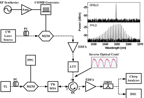
The all-optical RZ data-format converter is schematically shown in Fig. 1, in which a TWSOA DC-biased at 350 mA with a maximum gain at 1530 nm and an amplified spontaneous emission linewidth of 38 nm at 3-dB decay is employed. The inverse-optical-comb is generated by passing a continuous-wave laser source through an electrical-comb driven Mach-Zehnder intensity modulator (MZM) to temporally reshape the gain-window of the TWSOA, while the DC-level of the amplified electrical comb pulse at repetition frequency of 10 GHz is slightly offset from zero to obtain the maximum modulation depth of the inverse-optical-comb. Either a single-wavelength distributed feedback laser diode (DFBLD, Mitsubishi FU-68PDF) with a 3-dB linewidth of 1 MHz, or a multi-wavelength Fabry-Perot laser diode (FPLD, NEC 5501EH) with 3-dB linewidth of 7.3 nm is employed in our experiments for comparison, their corresponding spectra are shown in the inset of Fig. 1. A commercial electrical comb generator activated by a 10-GHz sinusoidal clock signal of 30 dBm generates electrical pulse-train of 30-ps pulsewidth, leading to the generation of an inverse-optical-comb (see inset of Fig. 1) with a duty-cycle of 70 % output from the MZM. After propagating through an erbium-doped fiber amplifier (EDFA) with 20-dB gain and an optical circulator (OC), the inverse-optical-comb is used to backward inject and then periodically deplete the gain of TWSOA for implementing non-return-to-zero to return-to-zero (NRZ-to-RZ) data format conversion. The incoming optical NRZ data-stream is simulated by encoding a tunable laser (TL) with another MZM, which is driven by a pseudo-random-bit-sequence (PRBS) data-stream generator with a pattern length of 223-1. The injection power at the port 2 of the OC is increased to saturate the gain of TWSOA for obtaining maximum on/off extinction ratio of the converted RZ data. The wavelength, input power and on/off extinction ratio (defined as the ratio of the “on level power” to the “off level power”) of the incoming optical NRZ PRBS data are 1529.2 nm, -15 dBm and 12 dB, respectively. The inverse-optical-comb is set at longer wavelength to achieve a better on/off extinction ratio of the converted signal will be obtained at the output [7]. Afterwards, the converted RZ data is analyzed by a chirp analyzer (Advantest Q7606B) to obtain its dynamic frequency chirp at different inverse-optical-comb injection power.
1530 1540 1550 1560 1570 -50 -25 -50 -25 FPLD Po w e r ( d B m ) Wavelength (nm) DFBLD
Fig. 1. Experimental setup. Amp.: amplifier.; ATT.: optical attenuator; DSO: digital sampling oscilloscope; EDFA: erbium doped fibre amplifier; OBPF: optical band-pass filter; OC: optical circulator; PC: polarization controller; PPG: PRBS pattern generator; TL: tunable laser. Electrical path: solid line. Optical path: dash line.
3. Simulation of Dynamic Chirp in Inverse-Optical-Comb Injected TWSOA
If we consider the optical signal evolution in the TWSOA under a slowly varying envelope approximation can express as [8, 9]
(
)
( )
( )
( ), 1 1 1 2 , , e g j z t out A A i gA z t A z t P z t eφ α υ ∂ + ∂ = − ∂ ∂ = , (1)where
A
is the output amplitude, υg is the group velocity, the parameter αe is a linewidthenhancement factor denoting as the ratio of the refractive-index variation to the gain variation under a transient change in pumping carrier density. Assuming the gain of TWSOA varies approximately linear with the carrier density (n) or carrier numbers (N) in a volume V, which is also a function of the spectral distribution of carriers, as described by
( )
(
)
(
)
( )
2 0 0 2 , 1 g g λ n a n n λ λ λ ⎡ − ⎤ ⎢ ⎥ = Γ − + ⎢ Δ ⎥ ⎣ ⎦ , (2) where Δλg denotes as the 3-dB spectral linewidth of the TWSOA gain, λ0 is the peakwavelength at carrier density n, a is the differential gain coefficient, Γ is the waveguide confinement factor of the TWSOA, and n0 is the carrier density required for transparency. A
transform among variables of τ=t–z/υg is introduced to simplify the solution, which leads to
dPout/dz=gPout and ∂φ/∂z=-αeg/2, and the rate equation of carrier density can be re-written as
( )
2 0 0 out c c g A gP dn I n I n d eV h V eV h Vτ
τ
= − −τ
ν
= − −τ
ν
, (3) where I is the biased current of TWSOA and τc is the spontaneous carrier lifetime. Bysubstituted Eq. (2) into Eq. (3), the transient gain of TWSOA is described as
( )
0 out c sat gP g g dg d E L τ τ τ − = − , (4) where the small-signal gain of TWSOA denotes as g0 = Γa(Iτc/e-N0)/V= Γan0(I/I0-1) with I0 =eτc/N0, Esat=hν0σ/a is the saturation energy with a modal cross-section ofσ=V/ΓL, and L is the
length of TWSOA. If we assume h(τ) as the integrated gain and define its relationship with
the input and output of TWSOA, the transient gain of TWSOA can be re-written by
( )
( )
( )
( )
( )
(
)
0 0 , ( ) ( ) 1 L h out in in in h c sat h g z dz P P e P G P g L h dh e d Eτ
τ
τ
τ
τ
τ
τ
τ
τ
= = ≡ − = − −∫
. (5)By using an inverse-optical-comb injection to deplete most of TWSOA gain within one period and leaving a narrow gain-window with a Gaussian shape in time domain, the input inverse-optical-comb waveform can be described as
( )
22 0 0 1 exp in in E P τ τ τ τ π ⎡ ⎛ ⎞⎤ = ⎢ − ⎜− ⎟⎥ ⎝ ⎠ ⎣ ⎦ , (6) where τ0 is the inverse-optical-comb pulsewidth. If we assume the decay of carriers areextremely slow as compared to the comb pulsewidth, the first term at the right-hand side of Eq. (5) can be completely subtracted to zero by the first term at the right-hand side of Eq. (6) in this case. In this case, only the stimulated recombination induced by the backward injected inverse-optical-comb dominates the gain dynamics in TWSOA. As a result, the residual gain
of TWSOA becomes an inverse shape of the injected inverse-optical-comb waveform with its peak equivalent to the saturated gain of the TWSOA. That is, the maximum backward injection energy is set as Pin = Ein/τ0π-1/2≈ [g0L/τc]Esat in our case. By substituting the Eq. (6)
into Eq. (5) and solving the rate equation, the transient power gain of TWSOA,
G(τ)=exp[h(τ)], is given by
( )
( ) 0 0 02 0 2 0 exp exp 2 4 2 h c c c c g L G τ e τ τ π τ τ erf τ τ τ τ τ τ τ ⎧ ⎛ ⎞ ⎛ ⎞⎫ ⎪ ⎪ = = ⎨− ⎜ − ⎟ ⎜ − ⎟⎬ ⎪ ⎝ ⎠ ⎝ ⎠⎪ ⎩ ⎭ . (7) where erf is an error function. Such a backward inverse-optical-comb injection eventually reshapes the continuous-wave gain of the TWSOA and confines it within a greatly shortened gain window. The dynamic frequency chirp imposed on the output of TWSOA can be derived from the phase modulation due to the carrier-induced transient variation on refractive index and gain of the TWSOA is obtained by differentiating the phase modulation as [10, 11](
)
2 0 2 2 2 2 0 0 0 2 2 4 0 0 0 0 0 0 0 4 0 0 0 4 2 2 2 0 0 2 1 2 1 1 1 2 2 ( ) 4 2 4 2 c c c c c c c c c e g c e sp g L e erf c e c c d d a n n dP R P d g L e erf g Le e τ τ τ τ τ τ τ τ τ τ τ τ τ π τ τ τ τ τ τ τ τ τ φ ν π τ α υ π τ α τ π τ τ τ τ π τ τ α π τ τ − − ⎛ ⎞ − −⎜ − ⎟ ⎛ ⎞ ⎝ ⎠ − ⎜ − ⎟ ⎝ ⎠ Δ = − ⎧ ⎡ ⎤⎫ ⎪ ⎪ = − ⎨− ⎢Γ − − ⎥⎬ ⎪ ⎣ ⎦⎪ ⎩ ⎭ ⎛ ⎞ = ⎜ − ⎟ ⎝ ⎠ ⎡ ⎛ ⎞ ⎢ ⎜ − ⎟ ⎢ ⎝ ⎠ = ⎢ + ⎢ ⎣ ( )( )
( )
1 1 2 4 in sat P f E e in sat c f P e f E τ τ α τ π τ − ⎤ ⎥ ⎥ ⎥ ⎥ ⎢ ⎥ ⎦ ⎡ ⎤ = ⎢ + ⎥ ⎣ ⎦.
(8)4. Results and discussion
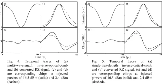
Under the injection of a multi-wavelength inverse-optical-comb pulse-train, the gain of TWSOA at those wavelengths covered by the multi-wavelength comb will simultaneously be depleted to leave a reshaped gain spectrum. If we set the injection optical spectrum at longer wavelengths, the conduction-band electrons at the bands covered by the injected spectral profile will be depleted by the inverse-optical-comb, and those at energy states higher than the injecting wavelengths can be left to give a transient gain for the input NRZ data. The simulation on transient gain and dynamic frequency chirp of TWSOA injected by inverse-optical-comb are shown in Figs. 2 and 3, respectively. These results corroborate that the dynamic frequency chirp of the TWSOA converted pulse data exhibits a strong dependence on the injected inverse-optical-comb power and pulsewidth. The reduction on the duty-cycle of injected inverse-optical-comb although shortens the pulsewidth of the converted RZ data bit, which also induces a larger frequency chirp since an equivalent gain depletion level is accomplished within a narrower time window. In experiment, the input NRZ data is converted into a RZ data with an improved on/off extinction ratio of 15.5 dB in the TWSOA under an inverse-optical-comb injection power of 16.5 dBm. Temporal traces of the inverse optical comb, the converted RZ data bit, and the corresponding dynamic frequency chirp obtained under multi- and single-wavelength injection conditions are shown in Figs. 4 and 5, respectively. The peak-to-peak frequency chirp related to the input NRZ signal, the multi- and single-wavelength inverse-optical-comb are determined as 1.0, 2.1 and 1.9 GHz, respectively. As the injection power of the inverse-optical-comb increasing from
2.4 to 16.5 dBm, the FWHM of the converted RZ signal is shortened from 41.2 to 31.6 ps, however, the peak-to-peak frequency chirp of the RZ data bit is concurrently enlarged from 6.7 to 11.1 GHz by using the multi-wavelength inverse-optical-comb injection.
-50 -25 0 25 50 0.0 0.2 0.4 0.6 0.8 1.0 g0=3 g0=5 N o rm alriz e d G a in ( a .u.) Time (ps) -50 -25 0 25 50 -5 0 5 10 g0=3 g0=5 Frequ e ncy Chirp (GHz ) Time (ps)
Fig. 2. Simulation of the transient power
gain, G(τ), of TWSOA backward injected
by inverse-optical-comb at different small-signal gain conditions.
Fig. 3. Simulation of the dynamic frequency chirp induced by the backward inverse-optical-comb injected TWSOA at different small-signal gain conditions.
In contrast to the multi-wavelength injection, the injection of single-wavelength inverse-optical-comb with same power level only consumes the carriers pumped upon the states with energy larger than injecting photons in the TWSOA. Therefore, the carriers left at low energy levels only accounts for the amplified spontaneous emission, which eventually contributes to the DC-level of the data-stream and causes a limited on/off extinction ratio of the converted RZ pulse. Under the single-wavelength inverse-optical-comb injection, the FWHM of the converted RZ signal is shortened from 37.3 to 30.8 ps as the injection power from 2.4 to 16.5 dBm, whereas the peak-to-peak frequency chirp of the RZ data bit is increased from 9.1 to 13.2 GHz. Apparently, the single-wavelength inverse-optical-comb injection shortens the converted RZ pulsewidth at a cost of enlarged dynamic frequency chirp as compared to the multi-wavelength case.
0 1 -7 0 7 0 1 -7 0 7
Fig. 4. Temporal traces of (a) multi-wavelength inverse-optical-comb and (b) converted RZ signal, (c) and (d) are corresponding chirps at injected powers of 16.5 dBm (solid) and 2.4 dBm (dashed).
Fig. 5. Temporal traces of (a) single-wavelength inverse-optical-comb and (b) converted RZ signal, (c) and (d) are corresponding chirps at injected powers of 16.5 dBm (solid) and 2.4 dBm (dashed).
Theoretically, the gain coefficient of TWSOA exhibits a Lorentzian lineshape described determined by both the pumped carrier concentration and the spectral distribution [12], as described in Eq. (2). The RZ data-format conversion occurred in TWSOA under the intense cross-gain depletion process not only results in patterning effect in time domain, but also induces a large chirp with its level proportional to the depth of gain depletion. Nonetheless,
the residual gain as well as the gain depletion depth of TWSOA can be minimized if we further shrink the gain distribution profile of TWSOA in spectral domain, since the derivative of gain coefficient to its spectral linewidth is always greater than zero, that is,
( )
(
)(
)
2( )
3(
)
2 0 0 0 , 2 g g 0 g dg n a n n d λ λ λ λ λ λ λ λ = Γ − − ⎡⎢⎣ Δ + − Δ ⎤⎥⎦> Δ . (9)Therefore, the dynamic frequency chirp of the converted RZ pulse is further reduced by shrinking the gain distribution of TWSOA in spectral domain. Temporal and spectral slicing on the gain of TWSOA can simultaneously be implemented by introducing a multi-wavelength inverse-optical-comb injection into the TWSOA.
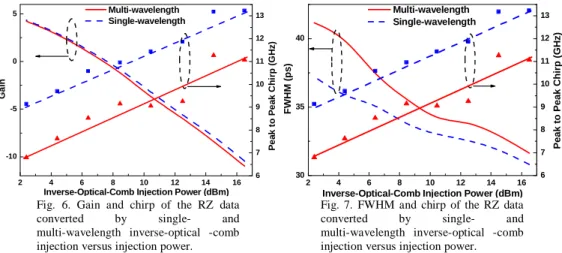
In more detail, the effect of the backward inverse-optical-comb injection power on the gain of TWSOA, the converted RZ pulsewidth, and the peak-to-peak chirp performance of the converted RZ at different injection conditions are analyzed and shown in Fig. 6 and 7. Figure 6 shows the gain and peak to peak chirp as a function of inverse-optical-comb injection power. The peak to peak chirp is increased as increasing injection power, since the phase of the converted signal rapidly increases due to carrier-induced index changes. In particular, the fluctuations on measured frequency chirp with changing injection power is due to the interference occurred between the injected and partially reflected inverse-optical-combs in TWSOA. Such an intense injection induced interference changes the carrier and gain dynamics in TWSOA and thus affects the pulse shape and dynamic frequency chirp [13]. On the other hand, for general optical time-division-multiplexing (OTDM) application, it is requisite to generate a RZ data bit with shorter duty-cycle or pulsewidth, thus enlarging the channel numbers and communication capacity. In principle, the limitation on converted RZ pulsewidth of the TWSOA-based RZ pulsed data converter is mainly determined by the effective carrier lifetime of τ= [τs-1 + d(gPin)/dn]-1 [14]. That is, the rise-/fall-time as well as the duty-cycle of the converted RZ data bit can essentially be shortened due to the decreasing carrier lifetime in a highly biased TWSOA with strong optical injection. The converted RZ pulsewidth is also plotted as a function of the inverse-optical-comb injection power and shown in Fig. 7. The observed rising time of the converted RZ pulse remain almost unchanged, however, the falling time was monotonically reduced by increasing the injection power of inverse-optical-comb. The evolution of converted RZ pulsewidth with injection power exhibits similar decreasing trend with its falling time.
2 4 6 8 10 12 14 16 -10 -5 0 5 6 7 8 9 10 11 12 13 Multi-wavelength Single-wavelength Ga in
Inverse-Optical-Comb Injection Power (dBm)
Pe a k t o Pe a k C h ir p (G Hz ) 2 4 6 8 10 12 14 16 30 35 40 6 7 8 9 10 11 12 13 Multi-wavelength Single-wavelength FWHM (ps)
Inverse-Optical-Comb Injection Power (dBm)
Peak to Peak Chirp (GHz)
Fig. 6. Gain and chirp of the RZ data converted by single- and multi-wavelength inverse-optical -comb injection versus injection power.
Fig. 7. FWHM and chirp of the RZ data converted by single- and multi-wavelength inverse-optical -comb injection versus injection power.
To provide a fast conversion speed and shortened response, the increase in both the biased current of the TWSOA and the injection power of inverse-optical-comb are mandatory. Nonetheless, the shortening of converted RZ pulsewidth inevitably results in a large dynamic frequency chirp under a same gain depletion depth of TWSOA. The increasing trend of the peak-to-peak dynamic frequency chirp with increasing gain of TWSOA (see Fig. 8) is plot
as a function of the inverse-optical-comb injection power at different biased currents of TWSOA are shown in Fig. 9. If we consider the effect of inverse-optical-comb power on the peak-to-peak frequency chirp, the first-order derivative of Eq. (8) gives an increasing trend of the dynamic frequency chirp with the inverse-optical-comb injection power Pin. That is,
( ) 1 0 0 in sat P f E in in sat in d P dC e dP E dP τ ν − Δ = ≥ , (10) where C0 is constant. It explains the lower frequency chirp of the converted RZ pulse
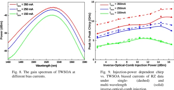
induced at lower biased current of TWSOA. As the injection power increases from 2.4 to 16.5 dBm, the increment of dynamic frequency chirp of the TWSOA converted RZ pulse data are 2.7, 3.2 and 4.4 GHz at TWSOA biased currents of 150, 250 and 350 mA, respectively. In comparison, it is observed that the multi-wavelength injection can provide better performance than single-wavelength injection on reducing the dynamic frequency chirp at higher injection powers. Since the gain spectrum of TWSOA becomes narrower at the multi-wavelength injection case, a more significant reduction on the dynamic frequency chirp with a broadband inverse-optical-comb injection can thus be expected.
1460 1480 1500 1520 1540 1560 1580 -60 -50 -40 ISOA = 350 mA ISOA = 250 mA ISOA = 150 mA Power (dBm) Wavelength (nm) 2 4 6 8 10 12 14 16 0 5 10 15 ISOA = 350mA ISOA = 250mA ISOA = 150mA P e a k t o P e a k C h ir p ( G H z )
Inverse-Optical-Comb Injection Power (dBm)
Fig. 8. The gain spectrum of TWSOA at different bias currents.
Fig. 9. Injection-power dependent chirp vs. TWSOA biased currents of RZ data under single- (dashed) and
multi-wavelength (solid) inverse-optical-comb injection.
In the practical fiber-optic communication network, even though the bit-error-rate performance of the converted RZ pulsed data during transmission is subject to the net effect of duty-cycle and frequency chirp, the receiving power penalty induced by improperly compensated chirp of the RZ pulsed data is a much more concerned factor when propagating through a fiber link. Our experiments conclude that the spectral slicing on the gain profile of TWSOA via multi-wavelength injection can thus be an efficient approach for reducing frequency chirp without seriously sacrificing the duty-cycle of the converted RZ pulse data. The BER of the input NRZ and output RZ after converting by the proposed system are measured and shown in Fig. 10. As a result, the BER performances of the back-to-back NRZ and the TWSOA converted RZ under DFBLD and FPLD based inverse-optical-comb injection reveal straightforward responses correlated well with their chirp and extinction characteristics. Due to the improvement on the on/off extinction ratio of the NRZ-to-RZ data formation conversion, there is a negative power penalty of -1 dB on the BER performance of the transformed RZ data-stream as compared to the input NRZ data at back-to-back transmission condition. In contrast, the multi-wavelength inverse-optical-comb injection also benefits from the slightly reduced chirp and enhanced extinction ratio (15.5 dB for FPLD injection and 13.5 dB for DFBLD injection), which eventually provides a BER response lower than the single-wavelength case. Even though, the BER results of two cases
tends to be coincident with each other due to the similar spontaneous emission noise characteristics. -24 -23 -22 -21 -20 -19 -18 -17 -16 -15 10-13 10-12 10-11 10-10 10-9 10-8 10-7 10-6 10-5 10-4 10-3 10-2 B it E rr o r R a te (B E R ) Receiving Power (dBm)
Fig. 10. BER performance of the back-to-back NRZ (blue circle) and the TWSOA converted RZ under DFBLD (black square) and FPLD (red diamond) based inverse-optical-comb injection.
The aforementioned results correlate well with our theoretical simulation that a multi-wavelength-injection induced gain-depletion of TWSOA can effectively reduce the dynamic frequency chirp in comparison with that obtained under single-wavelength-injection condition. Optimization of the RZ data-format conversion in the TWSOA with a temporally and spectrally sliced gain-window can thus be concluded. In comparison with the optical-optical (or all-optical) approach, the typical operation of NRZ-to-RZ conversion by using optical-electrical-optical (OEO) is currently limited by the finite bandwidth of the electronic NRZ-to-RZ IC (typically at 12.5 Gbit/s). Alternatively, the optical NRZ injection induced RZ data format conversion in a gain-switched FPLD or a gain-reshaped TWSOA via cross-gain modulation technique are currently two of the intriguing approaches. In our experiments, the problem on finite electrical modulation bandwidth of the FPLD and SOA can be overcome by employing the externally optical-injection modulation architecture. Such an approach is to transfer the bandwidth ‘bottleneck’ from the FPLD or TWSOA to the electrical comb RF amplifier and Mach-Zehnder modulator, since those devices are relatively easy to achieve higher bandwidth. Reshaping the gain profile in such a cross-gain depleted TWSOA can alternatively be achieved by using other broadband optical sources. Currently, there are two possible candidates for generating broadband dark-optical comb signal in our system. One is simply using a broadband ASE and the other is using a FPLD. Indeed, the multi-mode partition noise associated with the multi-wavelength dark-optical comb generated from the FPLD could be transferred into the converted signal. However, the use of a broadband ASE as the injection source also introduces large relative intensity noise and inevitably degrades the transmission as well as bit-error-rate performance of the converted RZ pulse. The multi-wavelength inverse-optical-comb injection with same power level are currently the best solution to benefit from advantages such as the complete carrier consumption above TWSOA bandgap and the lower dynamic frequency chirp induced during data-format conversion.
5. Conclusion
We have investigated the pulsewidth and dynamic frequency chirp characteristics of an all-optical RZ data-format converter by using a temporally and spectrally gain-sliced TWSOA,
in which cross-gain depletion is achieved by a backward single- or multi-wavelength inverse-optical-comb injection. In experiment, the effects of the inverse-optical-comb injection power on both the pulsewidth and the frequency chirp of the converted RZ pulse are theoretically elucidated. To provide a fast conversion speed and shortened response, the increase in both the biased current of the TWSOA and the injection power of inverse-optical-comb are mandatory. Reduction on duty-cycle of the injected inverse-optical-comb although shortens the pulsewidth of the converted pulsed data bit, which also induces a larger frequency chirp since the same gain-depletion level is accomplished within a narrower time window. Nonetheless, the residual gain as well as the gain depletion depth of TWSOA can be minimized if we further shrink the gain distribution profile of TWSOA by multi-wavelength inverse-optical-comb injection in spectral domain. This operation efficiently reduces the dynamic frequency chirp of the converted RZ pulse. Under the same injection power of 2.4 dBm, the multi-wavelength-injection converted RZ pulse data bit exhibits a peak-to-peak frequency chirp of 6.7 GHz, which is reduced by almost 40% as compared to the single-wavelength injection case. Such a reduction on the dynamic frequency chirp with a broadband inverse-optical-comb injection is theoretically explained due to the significant gain narrowing effect in TWSOA. A broadband inverse-optical-comb injection with an appropriate power level is expected as the best solution to benefit from advantages such as the complete carrier consumption above TWSOA bandgap and the minimized dynamic frequency chirp induced during RZ pulsed data-format conversion.
Acknowledgments
This work is partially supported by the National Science Council of Republic of China under grants NSC95-2221-E-002-448 and NSC96-2752-E-009-008-PAE.