W2E-(12)-4
COMPENSATION OF HIGHER-ORDER DISPERSION IN OPTICAL
COHERENCE TOMOGRAPHY WITH A RAPIDSCANNING OPTICAL
PHASE
DELAY LINE
I-Jen
Hsu,
Meng-Tsan Tsai, Chih-WekLu and C.
C.
Yang
Graduate Institute
of
Electro-Optical Engineering, National Taiwan University
Taipei, Taiwan, R.O.C.
(Phone) 886-2-23657624 (Fax) 886-2-23652637
(E-Mail) [email protected]
Abstract - We demonstrate a new methodfor compensating high er-order dispersion mismafch that is usually induced in afiber-based optical coherence tomography system wrth diflerent lengths offiber in the sample andreference arms.
Optical coherence tomography (OCT) is a useful technique for noninvasive biomedical imaging. For high-speed scan, a rapid-scanning optical delay line (RSODL) has been widely used in the reference arm of an OCT system. This arrangement has the advantages of high-speed linear scan, group- and phasedelay independencies, and easy group-velocity dispersion compensation. On the other hand, fiber-based
OCT
systems have been widely used with he advantages of high flexibility and stability. However, in combining a fiber-based OCT system with a phasecontrol RSODL in the reference arm, usually significant dispersion mismatch is introduced, particularly when the fiber lengths of the sample and referencearms
are different. A method of real-time dispersion compensation hy statically tilting the grating in the RSODL was proposed recently. However, this method can only compensate the dispersion that is linearly proportional to scan position and to achieve depthdependent dispersion compensation. In this paper, we proposed a new method of depth-independent compensation for higher-order dispersion mismatch in an OCT system. A wedged glass plate is placed between the grating and the lens of the RSODL Because different lengths of optical path are traced with the beams ofdifferent wavelengths in the wedged glass plate, and the refractive index of glass is dependent on wavelength in a nonlinear manner, compensation of higher-order dispersion mismatch can thus he achieved.If the signal of the center wavelength propagates along the optical axis of the lens toward the tilting mirror with its axis of rotation offset by
a.
and the grating surface is perpendicular to the optical axis of the lens, the wavelennthdeoendent Dhase delav without the existence of wedged glass d a t e can he exDressed asHere, f is the focal length of the lens, d is the grating period, c is the speed of light, and
Wf)
is the angle of the tilting mirror at time 1. When the wedged glass plate is placed between the grating and the lens, the optical beams with different wavelengths trace with different lengths of optical path viaHere,
a
is a factor dependingon
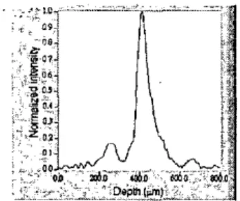
the angle and the position of the wedged glass plate. The refractive index n ( 4 is dependent on the wavelength via the Sellmeier equation. By inserting the wedged glass plate, the wavelength-dependent refractive index will result in an extra phase delay, which depends on wavelength in a nonlinear manner. In experiments, a fiber-based OCT system was built with a mode-locked Tksapphire laser (12 fsec in pulse width) as its light source. The lengths ofthe fibers in the sample and reference arms are2 m
and 1.8 m, respectively. Figure I shows the interference fringe envelope obtained by scanning a reflection mirror. The signal was highly chirped due to the dispersion mismatch between the sample and reference arms. When the wedged glass plate was inserted between the grating and the lens and rotated to an appropriate angle, the width of the interference fringe envelope was significantly reduced, as shown in Fig. 2.A l ( W ) = a n ( a , ) A W ' (2)
Fig. I The interference fringe envelope from a single reflection without dispersion compensation.
Fig. 2 The interference fringe envelope from a