An Adaptive Polling Scheme to Improve Voice Transmission over
Wireless LANs
Ashraf D. Milhim and Yaw-Chung Chen
Department of Computer Science, National Chiao Tung University, Hsinchu, Taiwan
{[email protected], [email protected]}
Abstract
Motivated by the promising voice over IP technology, and the wide availability of WLANs, the application of Voice over WLAN (VoWLAN) is expected to encounter dramatic growth in the near future. IEEE 802.11e standard was established to achieve a high level QoS, it introduced a new medium access mechanism HCF in order to solve the QoS provisioning problem in the legacy IEEE 802.11. In this work we propose an adaptive polling scheme, which works on the HC side in HCCA mode, in which HC maintains two dynamic polling lists to reduce both access delay and polling overhead. Both VBR and CBR traffic are taken into consideration. Simulation results showed that the polling overhead is reduced significantly, in addition to high throughout and low access delay comparing to the classical Round-Robin polling scheme and the reference scheme in the standard.
1. Introduction
In recent years, Voice over Internet Protocol (VoIP) became one of the most popular Internet applications. The popularity of VoIP comes from its low cost and good quality, thus, people can use their PCs instead of the traditional telephone or cellular phone to make calls.
To provide person-to-person connections anywhere and anytime, the wireless networks is essential for Internet access. However, to achieve a high level service quality, voice over 802.11 faces a lot of challenges,∗such as large interference, long latency, high loss rates, and jitter. Furthermore, the distributed coordination function (DCF) and the point coordination function (PCF) defined in basic IEEE 802.11 are unable to guarantee QoS effectively.
To solve the problems of QoS, the IEEE 802.11 working group chartered the 802.11e task group with the responsibility of enhancing the 802.11 Medium Access Control (MAC) to include bidirectional QoS to support latency-sensitive applications. The new standard of IEEE
∗ This work is sponsored in part by National Science Council under grant
no. NSC 94-2752-E009-006-PAE
802.11e [1] is expected to solve the QoS problem of real-time applications over wireless local area networks.
The rest of this paper is organized as follows: Section 2 introduces the background of IEEE 802.11e, Section 3 points to the problem definition that motivated us to do this work. In Section 4, we discuss the proposed adaptive polling scheme. We demonstrate our simulation and numerical results in Section 5. Finally the conclusion is presented in Section 6.
2. The IEEE 802.11e MAC
IEEE 802.11e features many enhancements, some are general and some are specific. The general enhancements are: the Direct Link Protocol (DLP), the introduction of negotiable acknowledgements, traffic parameterization and traffic prioritization. The major novelty developed by IEEE 802.11e is the new coordination function called Hybrid-Coordination Function (HCF). It combines aspects of the distributed coordination function and the point coordination function. HCF uses a contention-based channel access method, called the Enhanced Distributed Channel Access (EDCA), as well as a contention-free-based mechanism, called HCF-Controlled Channel Access (HCCA) for accessing to the wireless medium.
2.1. Enhanced Distributed Channel Access
EDCA is designed to enhance the DCF mechanism and to provide a distributed access method that can support service differentiation among classes of traffic. The EDCA mechanism provides differentiated and distributed access to the wireless medium for QoS-enabled stations (QSTAs) using eight different user priorities (UPs). The EDCA also defines four access categories (ACs) for supporting the delivery of traffic with UPs at the QSTAs.
2.2. HCF Controlled Channel Access
The HCCA is a centralized access mechanism controlled by the Hybrid Coordinator (HC), which resides in the QoS-enabled Access Point (QAP). Each QSTA may have several established Traffic Streams (TS), a TS is characterized by a Traffic Specification (TSPEC) which is negotiated between the QSTA and the QAP. Mandatory
fields of the TSPEC include: Mean Data Rate, Delay Bound, Maximum Service Interval, and Nominal SDU Size. For all established streams the QAP is required to provide a service that is compliant with the negotiated TSPEC under controlled operating conditions. IEEE 802.11e compliant stations must be able to process the additional frames reported in Table 1.
Table 1: QoS frames.
The QAP enforces the negotiated QoS guarantee by scheduling Controlled Access Phases (CAPs). A CAP is a time interval during which the QAP may either transmit MSDUs of established downlink TSs or poll one or more QSTAs by specifying the maximum duration of the transmission opportunity (TXOP). A QSTA is never allowed to exceed the TXOP limit imposed by the QAP, including inter-frame spaces and acknowledgments.
After a frame is received it is classified to be served by either HCCA or EDCA. In the former case, this frame must be added into the appropriate transmission queue, because each traffic stream (TS) is assigned to a unique queue. Each of those FIFO transmission queues contains packets of the station that initiated the TS.
3. Problems Definition
In this section we will focus on some scheduling problems in IEEE 802.11e HCCA. For instant, Round-Robin (RR) polling mechanism has the following problems:
Inefficient Fairness polling: when an HC enforces fair access to all stations regardless they were talking or silent, it wastes the resources that should be reserved for the talking stations with higher priority than the silent stations.
Polling overhead: overhead in HCF is due to frequent poll frames from the AP to mobile stations [2].
High delays: with the increase of network population, talking stations usually suffer long access delays, because they are forced to wait until the HC has polled all the stations, which may be silent, before them in the polling list.
4. Proposed Adaptive Polling Scheme
Based on the problems addressed earlier, in order to eliminate the problem of polling fairness, as well as to minimize both the polling overhead and delay, we propose
an Adaptive Polling Scheme (APS) to poll the VoIP stations efficiently under the HCCA mode.
4.1. Architecture of the proposed scheme
The proposed APS maintains two polling lists, a talking polling list and a silence polling list. It consists of two modules, a Silence Detector & List Manager (SDLM) module, and a Polling Decision Maker (PDM) module. Architecture of our proposed scheme is shown in Figure 2.
Frames arriving at the HC’s MAC are classified first in order to be served by either EDCA or HCCA. If a frame was classified to be served by HCCA, it should be inserted into the appropriate transmission queue.
Figure 1: Architecture of the proposed scheme.
Since each admitted stream is assigned to a transmission queue on the HC, SDLM detects the state of the source station that has sent the packet to the HC, then it updates the appropriate polling list. When a frame is removed from the transmission queue in order to be sent to the destination station, SDLM will be invoked again to update the appropriate polling list. As a result, the two polling lists are reordered according to their stations state, the number of buffered packets in the AP queues, and the number of buffered packets in the TC voice queue on the station side. Reordering those lists in this manner makes it efficient to poll them sequentially. The PDM is responsible for polling stations in the two polling lists, and determining TXOPs for traffic streams.
4.2. The talking list structure
Each element in the talking list encapsulates the following information:
QNoP: the number of packets buffered in the transmission queue of a specified TSID on the AP side.
SNoP: the number of packets buffered in the TC on the station side, and it is calculated on the AP side by our scheme using the information in the TSPEC sent by the station.
4.3. The silence list structure
Each element in the silence list encapsulates the TSID and QNoP information as described above.
4.4. Updating polling lists
SDLM updates the talking and the silence polling lists based on the events that may occur on any one of the transmission queues, the procedure of updating the two polling lists are explained in the next subsection.
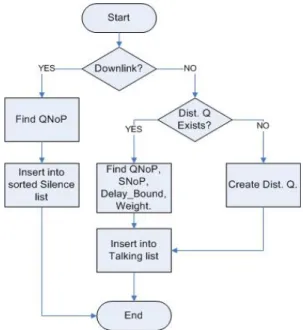
Silence detection. First of all, when a station requests a
HCCA to access the medium and the stream is admitted by the admission control policy on the AP, SDLM will check the direction field of the TSPEC, if it is uplink then SDLM will consider this station as a talking station and it checks whether the transmission queue is already existed. If it wasn’t, then a new transmission queue is created and assigned to the new TSID, SDLM then inserts this TSID to the top of the talking polling list. If the queue has already been created then SDLM calculates a weight as described in equations 1 and 2, then it inserts this TSID element into the talking polling list at the appropriate place, because the talking polling list must be sorted in descending order according to the weight. If the direction field was downlink then SDLM will consider this station as a silent station and insert its TSID into the silence polling list at the appropriate placement according to QNoP, because the silence polling list is ordered in descending order according to the QNoPs of the TSIDs. Figure 2 shows a flowchart of the initialization and silence detection procedure of SDLM.
(1)
(2)
Where R is the mean data rate, MSI is the maximum service interval, and MSDU size is the nominal packet size.
When the AP starts polling stations, and if the polled station was silent, this station will reply a null or a silent
packet depending on the codec operating on it. CBR codecs generate silent packets while VBR codecs generate null packet when the station is silent, otherwise, both codecs generate a data packet. There are two cases of the polled station:
A. If this station was in the talking list, the HC checks the reply packet type as follows:
If the reply was a NULL or silence packet, then remove this station from the talking list and add it into the tail of the silence list.
If the reply was a data packet, then keep it in talking list and reorder the list.
B. If this station was in the silence list, then check the reply packet type as follows:
If the reply was a data packet then remove this station from the silence polling list and add it into the top of the talking list.
If the reply was a NULL packet or a silence packet then update the QNoP and insert the station in the new place according to QNoP. Figure 3(a) shows a flowchart of primary silence detection for the talking list, while Figure 3(b) shows a flowchart of primary silence detection for the Silence Lists.
Figure 2: A flow chart of initial silence detection. Reordering the lists. After inserting a frame into the
appropriate queue, an update should be done on the QNoP value in the corresponding entry in the talking list or silence list, this update is done by incrementing the value of QNoP by one (QNoP=QNoP + 1). Another update happens when a frame is dequeued from the transmission queues in order to be sent, i.e. (QNoP = QNoP – 1). In the proposed scheme we use three schedule elements of TSPEC to find out the number of buffered frames on the station side (SNoP) as shown in Equation (1), then update
MSDUsize
MSI
R
SNoP
=
×
bound
Delay
QNoP
SNoP
Weight
_
2×
+
=
SNoP variable in talking list. After each update on any list it should be reordered. The talking list should be sorted according to QNoP and SNoP but by giving QNoP higher weight than SNoP, i.e. it is sorted dynamically according to the result of Equation (2), while silence list is reordered after each update according to QNoP. So now we have the talking list and the silence list sorted in descending order according to Weight and QNoP respectively. The purpose of those updates is to keep the information needed to take polling decision updated at any time, and to maximize the usage of piggybacking function.
Figure 3(a): Talking list management.
Figure 3(b): Silence list management
4.5. TXOP Calculation
Since the HC can also grant TXOPs, by sending QoS(+)CF-Poll frames, during the CP, it is not mandatory for the HC to use the CFP for QoS data transfers, therefore, in our scheduler we only use CAPs to transfer QoS data, in which the HC use a mix of EDCA and HCCA.
We distinguished between the TXOPs granted to the talking stations and that granted to the silent stations, we used the calculation method mentioned in the standard to calculate TXOPs for the talking stations, and we proposed another method to calculate TXOPs for the silent stations. It is more accurate to calculate talking stations TXOP according to TSPEC fields and to calculate silent stations TXOPs according to the current downlink flow statistics on the HC.
To calculate the TXOP intervals for the talking stations we use, the following TSPEC parameters: Mean Data Rate, Nominal MSDU size, and maximum service interval. The service period is determined as follows:
Find the minimum of maximum service intervals of admitted streams m.
SP is the maximum number no greater than m and is submultiple of the beacon interval.
Calculate the number of MSDUs that are expected to be sent with the mean data rate during the SI:
×
=
i i iL
SI
N
ρ
(3)
Where ρi is Mean Data Rate for stream i, Li is the Nominal MSDU Size of stream i.
Calculate TXOP duration for stream i:
+
+
×
=
O
R
M
O
R
L
N
TXOP
i i i i imax
,
(4)
Where Ri is the Physical Transmission Rate, O is the overhead, and M is the maximum allowable size of MSDU, i.e., 2304 bytes.
The TXOPs of silence stations are calculated as follows:
Find the transmission queue with the minimum number of buffered packets, k.
Calculate TXOP for stream i as follows:
×
+
+
=
O
R
M
O
R
L
k
TXOP
imin
,
(5)
Where R is the physical transmission rate, O is the overhead, and M is the maximum allowable size of MSDU, i.e., 2304 bytes.
4.6. Polling the talking and silence lists
Depending on the information stored in the talking list and silence list, PDM will start polling stations that reside on those lists starting from top of talking list and ending at the tail of silence list.
Polling the talking list. PDM starts polling stations in
talking polling list from the top to the tail of the list, talking list is already sorted according to QNoP and SNoP, where the stations that have the highest priority reside at the top of the list and priority is getting lower as we go down in the list.
Because the elements on the top represent the stations that have buffered packets on AP and station, then it is efficient to turn the IEEE 802.11e piggybacking feature on. As we mentioned in the previous section, CF-Poll is a control packet and it is sent using the basic data rate, this increases the polling overhead significantly comparing to the time required to send QoS Data, but when we turn the piggybacking on, then the piggybacked (QoS Data + CF-Poll) or the (QoS Data + ACK) packets are considered as data packets and could be sent at the negotiated data rate between the station and the HC. This will decrease the polling overhead, especially because of the dynamically sorted talking polling list discussed above.
Polling silence list. Silence polling list is ordered
according to QNoP, stations in this list are given priorities such as stations in talking polling list, but all stations in silence polling list has lower priority than those in the talking polling list. After polling all stations in talking polling list, PDM tells the HC to start polling stations in silence polling list from the top to the tail of the list. In the next beacon interval HC starts polling from the top of the talking list again.
5. Simulation and Numerical results
5.1. Simulation environment
The simulation environment consists of one QAP and a varying number of stations, all of those stations are initiating voice calls, and operating on IEEE 802.11b. The MAC and physical parameters are shown in Table 2.
We assumed that the channel is error-free and no hidden stations exist, thus RTS/CTS feature is turned off, while the piggybacking feature is turned on.
We used NS2 (ns-allinone-2.27) simulator to evaluate the performance of our scheme, we compared our scheme with two other schedulers, the reference scheduler
mentioned in the standard in addition to the round robin scheduler.
5.2. Simulation results
We compared the above mentioned schedulers among different criteria, we measured throughput, delay, and packet loss ratio for different network sizes, and the results are described as follows:
From Figure 4 we can find a significant increase in the throughput for APS comparing to RR and reference schedulers. Reference scheduler starts at 0.5 Mbps when the network consists of 4 mobile nodes, as well as APS and RR. Throughput keeps increasing for all schedulers when the number of mobile nodes is 8, with a little difference for RR’s and APS’s account. The gap between APS, RR, on a hand and the reference on the other hand is increased when the network size becomes larger.
Reference scheduler can support a limited number of transmission queues, which means that the number of supported voice stations is limited, when the network size increases, its performance doesn’t show any improvement.
The differentiation between the stations in the talking state and the stations in silence state, the ordered polling list according to the traffic directions and the TXOPs calculation method played an important role to make this difference.
Figure 5 shows the average transfer delay against different network sizes, it shows a significant growing gap between RR and reference schedulers on one side and APS scheduler on the other side. The higher delay in both RR and reference scheme is primarily due to the polling overheads, in addition to the fairness in polling stations, which reaches 99.98% for the reference scheduler; while APS shows a very low delay comparing to the other two schemes, this gap is explained by the unfairness and piggybacking features of the APS.
Figure 4: Total throughput against network size for Reference, APS, and RR schedulers
Figure 5: Average delay against network size for Reference, APS, and RR schedulers
Figure 6 shows the packet loss ratio, it shows a good performance for APS comparing to the two other schemes. Voice packets are generated continuously every 20 ms in G.711 codec, which means that those stations should be polled as prompt as possible to give them the chance to send their voice packets, but in RR and reference schedulers, with the increase of the network size, talking station may not be polled at the right time, thus, stations may start dropping packets from their TCs, and this is the main reason of the packet loss ratio in RR and reference schedulers. On the other hand, APS classifies stations into several types and give each type a priority to be polled, talking stations will be at the top of the priorities so the talking stations will always have the chance to send their packets, this will affect the packet drop ratio positively, and enhance the overall performance.
Figure 6: Packet loss ratio against network size for Reference, APS, and RR schedulers
5.3. Polling Overhead analysis
Now we show analytically how polling overhead is decreased in APS comparing to RR. Our analysis inputs are: fixed TXOPs of 10 ms, Beacon interval of 100 ms, and 4 mobile nodes.
The polling frame consists of 36 bytes. It should be sent at the base rate (2 Mbps), the PHY overhead is considered to be 192 µs. the total transmission time for the CF-Poll packet transmission is (36 * 8 / 2) + 192 = 336 µs. The 4 stations may be polled 2.5 times at maximum and not polled at all at minimum, so let’s say the average of the 4 stations to be polled is (0 + 2.5) / 2 = 1.25 times. For 4 stations there will be 4 * 1.25 CF-Polls per Beacon interval which is equals 6 CF-Polls. The total transmission time for those 6 CF-Poll packets is 6 * 336 = 2016 µs per beacon interval. If we run the RR for 500 second, then the total CF-Poll transmission time is 2016 * 5 = 10080 µs = 10.08 ms. From the transmission time for the voice packet of G.711 codec is 196 * 8 / 11 = 142.55 µs, we can notice how many voice packets we can send during the polling overhead.
In APS we use piggybacking, and according to the way we order the polling lists it will be much more efficient to send a QoS Data + CF-Poll than sending only CF-Poll, especially that the piggybacked packet is considered to be a data packet, and it could be sent on the negotiated data rate between station and HC, and by doing the same calculations as we did for RR, we get (36 + 160) * 8 /4 = 392 µs to send one poll and one voice packet on the data rate of 4 Mbps, for 6 polls 392 * 6 = 2352 µs and for 5 beacon intervals 2352 * 5 = 11760 µs = 11.76 ms compared to 10.08 ms for RR but with the difference that we have sent 30 voice packets piggybacked with the Poll packets. Sending the same number of voice packets that have been sent piggybacked with CF-Polls in APS without piggybacking costs (160 * 8 / 11) * 6 * 5 = 3490.9 µs on 11 Mbps data rate. By subtracting the time required to transmit those voice packets without piggybacking them with CF-Polls 11760 – 3490.9 = 8269.1 µs = 8.3 ms.
Table 3: Percentage of enhancement for APS against RR and Reference
.
Based on the previous results we can notice a significant enhancement in APS comparing to the Reference and RR polling mechanisms. Table 3 shows the enhancement percentage of APS against RR and Reference.
6. Conclusion
This paper introduces a new scheduling scheme to enhance the performance of VoIP traffic on wireless local area networks. The new scheduling scheme maintains two dynamic lists, talking polling list and silence polling list. Both of them are updated dynamically according to the state of stations depending on a silence detection mechanism as well as the queue occupancy on the AP and the stations.
The simulation results show a significant enhancement in performance using our proposed scheduling scheme comparing to the reference scheduler in the standard and the classical round-robin scheduler.
References:
[1] IEEE Standard 802.11e-2005.
[2] Ping Wang, Hai Jiang and Weihua Zhuang, “IEEE 802.11E Enhancement for Voice Service,” IEEE Wireless Communications, February 2006, pp. 30-35.
[3] Oran Sharon and Eitan Altman, “An Efficient Polling MAC for Wireless LANs,” IEEE/ACM Transactions on Networking, Vol. 9, No. 4, August 2001, pp. 439-451. [4] Jungbo Son, Hosuk Choi and Sin-Chong Park, “An
Effective Polling MAC Scheme for IEEE 802.11e,” Proceedings of International Symposium on Communications and Information Technologies 2004 (lSCIT 2004), Sapporo, Japan, October 26- 29, 2004, pp. 296-301.
[5] Jun Zheng and Emma Regentova, “An Improved Polling Scheme for Voice Support in IEEE 802.11Wireless Network,” Proceedings of the International Conference on Information Technology (ITCC’05), Vol. 2, pp. 603-608. [6] Young-Jae Kim, and Young-Joo Sun, “Adaptive polling
MAC schemes for IEEE 802.11 wireless LANs supporting voice-over-IP (VoIP) services,” Wireless Communications and Mobile Computing, Vol. 4, No. 8, December 2004, pp. 903–916.
[7] Takehiro Kawata, Sangho Shin and Andrea G. Forte, “Using Dynamic PCF to Improve the Capacity for VoIP Traffic in IEEE 802.11 Networks,” Proceedings of IEEE Wireless Communications and Networking Conference, 13-17 March 2005, Vol. 3, pp.1589 – 1595.
[8] Yaser Pourmohammadi Fallah and Hussein Alnuweiri, “A Controlled-Access Scheduling Mechanism for QoS Provisioning in IEEE 802.11e Wireless LANs,” Proceedings
of the 1st ACM international workshop on Quality of service & security in wireless and mobile networks, October 2005, pp.122-129.
[9] Zvi Ganz, Aura Ganz and Kitti Wongthavarawat,
Multimedia Wireless Networks: Technologies, Standards and QoS. 2003 Prentice Hall.