光纖光柵波長塞取多工/交接系統與 寬頻光放大技術之設計
157
0
0
全文
(2)
(3)
(4) 誌 謝 (Acknowledgments) 首先要感謝指導教授陳永光博士這些年來的悉心指導與關懷,帶領 學生進入光纖通信的領域,並時常地指導學生如何去作實驗及如何思考 問題,更讓學生有機會到國家級的研究機關–中華電信研究所來完成論文 研究。除此之外,更要感謝中華電信研究所線路研究室涂元光主任、計 畫主持人蔡福源先生,及前瞻研究室廖枝旺主任提供主要儀器設備和研 究機會讓論文得以完成,僅在此深致敬意與謝意。 在實驗方面,感謝中華電信研究所曾松齡博士、馮開明博士與李健 仲先生給予實驗上許多的幫助、江衍旭先生與盧明寬先生在電子電路上 的協助,王志益先生和吳嘉憲先生在實驗儀器上的支援。在論文的理論 模擬部分,要感謝高雄海洋技術學院梁財春教授的協助。由於這些幫助, 使本論文才能夠順利完成,特於此表示萬分感謝之意。 回想實驗期間中,得到許多人的協助,感謝蘇景弘、楊宜龍與郭萓 侑學弟在實驗和資料處理上的幫助;另外,中山光通信實驗室的學弟妹 們,所給予我的鼓勵與扶持,使本論文得以順利完成,也在此一併感謝。 最後將本論文獻給我最敬愛的父親張麗在先生及母親李碧嬌女士, 以及我的弟弟和妹妹!由於您們的關懷與支持,使我能安心完成博士學 位,特以本文表達由衷的感恩之情。. i.
(5) 中 文 摘 要. 本論文針對分波多工長距離幹線與環形網路,設計幾項重要元件與系統在分波 多工網路中的應用,如光纖光柵分波多工塞取/交接系統、多模光纖區域網路及雙向 次載波類比視訊傳輸系統,寬頻光放大器在都會區域網路之應用。光纖光柵分波多 工塞取/交接系統方面,已有許多相關性的技術研究,首先利用多個埠的光旋轉器與 光纖光柵來作為降低串音並簡化光纖光柵的架構;除此之外,也提出利用馬克-詹德 式光纖布拉格光纖光柵元件,配合光開關串接建構成一大型的多波長且不需要外加 多工或解多工器的光纖光柵波長塞取/交接多工器,來完成固定型和可動態選擇型波 長塞取/交接多工的機制。 在多模光纖區域網路及雙向次載波類比視訊傳輸系統部分,我們提出在多模光 纖區域網路上進行同時傳輸 1.55 µm 調幅視訊信號與傳輸速率為 155 Mb/s 的 1.3 µm 數據信號,研究結果證實可利用以佈放的區域網路作為視訊廣播與資料傳輸的展 示。另外,利用光旋轉器和光濾波器、多工/解多工器來達成雙向無中繼/中繼放大的 系統實驗,並且也探討如何延伸傳輸的距離與消除散射干擾,因此對類比調幅視訊 在環形區域網路與點對點雙向的都會區域網路之傳輸可能性作展示。 寬頻光放大器在都會區域網路之應用方面,我們探討不同雙向泵激架構混合調 幅視訊/數位系統傳輸之研究的摻鉺光纖放大器,以及展示結合拉曼放大與半導體光 放大器的寬頻光放大器,來同時作為多個 10 Gb/s 傳輸系統的色散和傳輸損失補償, 研究結果有益於分波多工長距離幹線與環形網路的規劃和設計。. ii.
(6) ABSTRACT In this dissertation, we investigate the designs and applications of fiber Bragg grating-based. optical. add-drop/cross-connect. multiplexing. systems. for. WDM. long-distance trunk and ring networks, multiple AM-VSB signals transmission systems, and wideband optical amplifiers in metropolitan area network. In fiber Bragg grating-based optical add-drop/cross-connect multiplexing systems, the utilization of multi-port circulator and fiber Bragg gratings can hugely reduce the crosstalk and compact the configurations. Furthermore, we propose the utilization of Mach-Zehnder fiber Bragg grating-based devices with the associated mechanical Optical switches to construct large-dimension fixed and reconfigurable optical add-drop/cross-connect multiplexing system without the needs of additional WDM multiplexers and demultiplexers. In multiple AM-VSB signals transmission systems, we demonstrate the transmission of AM-VSB CATV video signal at 1.55-µm and 155-Mb/s data signal at 1.3-µm over a multi- mode fiber local area network (MMF-LAN) link. On the other hand, we not only demonstrate the possibility of optical circulator with optical bandpass filter, and MUX/DEMUX configurations, but also discuss the transmission distance of extension and the elimination of crosstalk for bi-directional transmission systems of multiple AM-VSB CATV signals. The system demonstration confirms the feasibility of multiple AM-VSB signals over the existing MMF-LAN and bi-directional transmission systems. For the application of wideband optical amplifiers in metropolitan area network, we also present erbium-doped fiber amplifier (EDFA) for hybrid WDM systems, and the dispersion-compensated gain-clamped 90 nm wideband optical amplifier in 10 Gb/s DWDM transmission systems. These designs, demonstrations, and results will be useful for WDM long-distance trunk and ring networks applications.. iii.
(7) List of Contents Page Acknowledgments ................................................................................................................ i Chinese Abstract...................................................................................................................ii English Abstract ..................................................................................................................iii List of Contents ................................................................................................................... v List of Tables .......................................................................................................................ix List of Figures...................................................................................................................... x List of Acronyms ................................................................................................................xv. Chapter 1 General Introduction........................................................................................... 1 1.1 Brief Introduction of WDM Architectures.......................................................... 1 1.2 Review of Fiber Bragg Gratings .......................................................................... 2 1.3 Properties of Wideband Optical Amplifier .......................................................... 4 1.4 The Dissertation Organization ............................................................................. 7 Chapter 2 Overview and Motivation................................................................................... 9 2.1 Fiber Bragg Grating- Based Multiplexing Systems .............................................. 9 2.1.1 Low-Crosstalk and Compact Optical Add-Drop Multiplexer Based on A Multi-Port Circulator and Fiber Bragg Gratings….. ...................................... 10 2.1.2 Mach-Zehnder Fiber Bragg Grating-based Fixed and Reconfigurable Optical Add-Drop Multiplexers .................................................................................. 10 2.1.3 Mach-Zehnder Fiber Bragg Grating-based Dynamic Optical Cross-Connect ................................................................................................ 12 2.2 Multiple AM-VSB Signals Transmission Systems ............................................ 12 2.2.1 Simultaneous Video and Data Signals Transmission System over Multi-Mode Fiber Local Area Network……………………………………13 2.2.2 Repeaterless Bi-directional Transmission of Multiple AM-VSB CATV Signals ........................................................................................................... 13 2.2.3 Bi-directional AM-VSB 100 km Transmission Systems .............................. 14. v.
(8) 2.3 Wideband Optical Amplifier for Metropolitan Area Network ........................... 15 2.3.1 Erbium- Doped Fiber Amplifier for Hybrid WDM Systems ........................ 15 2.3.2 Dispersion-Compensated Gain-Clamped 90 nm Wideband Optical Amplifier......................................................................................... 16 Chapter 3 Fiber Bragg Grating-based Optical Add-Drop Multiplexing and Cross-Connect Systems .............................................................................................................. 17 3.1 Low-Crosstalk and Compact Optical Add-Drop Multiplexer Using a Multi-port Circulator and Fiber Bragg Gratings .................................................................. 17 3.1.1 Optical Add-Drop Multiplexing Configurations and Experimental Setup ... 17 3.1.2 Experimental Results and Discussions ......................................................... 19 3.1.3 Summary....................................................................................................... 20 3.2 Mach-Zehnder Fiber Bragg Grating-Based Fixed and Reconfigurable MultiChannel Optical Add-Drop Multiplexers for DWDM Networks ....................... 20 3.2.1 Basic MZ-FBG Add-Drop Devices .............................................................. 21 3.2.2 Fixed MZ-OADM Architecture ................................................................... 23 3.2.3 Reconfigurable MZ-OADM Architectures .................................................. 24 3.2.4 Characteristic Comparison and Dimension Limits....................................... 26 3.2.5 Discussions and Summary............................................................................ 35 3.3 Mach-Zehnder Fiber Bragg Grating-based Dynamic Optical Cross-Connect System ................................................................................................................ 37 3.3.1 Optical Cross-Connect Architecture............................................................. 38 3.3.2 Experimental Setup and Results ................................................................... 38 3.3.3 Discussions and Summary............................................................................ 39 Chapter 4 Multiple AM-VSB Signals Transmission Systems ........................................... 41 4.1 Simultaneous Transmission of 1.55-µm Video and 1.3-µm Data Signals Transmission System over a Multi-Mode Fiber Local Area Network ................ 41 4.1.1 Network Configuration and Design.............................................................. 41 4.1.2 Experiment and Demonstration.................................................................... 43 4.1.3 Experimental Results and Discussions ......................................................... 44 4.1.4 Summary....................................................................................................... 45. vi.
(9) 4.2 Repeaterless Bi-directional Transmission of Multiple AM-VSB CATV Signals over Conventional Single-Mode Fiber ............................................................... 45 4.2.1 Experimental Setup ...................................................................................... 46 4.2.2 Experimental Results and Discussions ......................................................... 47 4.2.3 Summary....................................................................................................... 48 4.3 Bi-directional Lightwave CATV 100 km SMF and LEAF Transmission System ................................................................................................................. 49 4.3.1 Experimental Setup ...................................................................................... 49 4.3.2 Results and Discussions ............................................................................... 50 4.3.3 Summary....................................................................................................... 51 Chapter 5 Wideband Optical Amplifiers for Metropolitan Area Networks ...................... 52 5.1 Erbium- Doped Fiber Amplifier for Hybrid Digital/Analog WDM Systems ..... 52 5.1.1 H-WDM EDFA Configurations and Modeling ............................................ 52 5.1.2 Characteristic Comparison ........................................................................... 55 5.1.3 Simulation Discussions ................................................................................ 58 5.1.4 Summary....................................................................................................... 59 5.2 Dispersion-Compensated Gain-Clamped 90 nm Wideband Optical Amplifier for Metropolitan Area Network ............................................................................... 60 5.2.1 Experimental Setup ...................................................................................... 60 5.2.2 Results and Discussions ............................................................................... 61 5.2.3 Summary....................................................................................................... 62 Chapter 6 Conclusions ....................................................................................................... 63 References ......................................................................................................................... 67 Tables................................................................................................................................. 78 Figures ............................................................................................................................... 87 Biography ........................................................................................................................ 137 Publication List................................................................................................................ 138 Errata … … … … … … … … … … … … … … … … … … … … … … … … … … … … … … … . 1 3 9. vii.
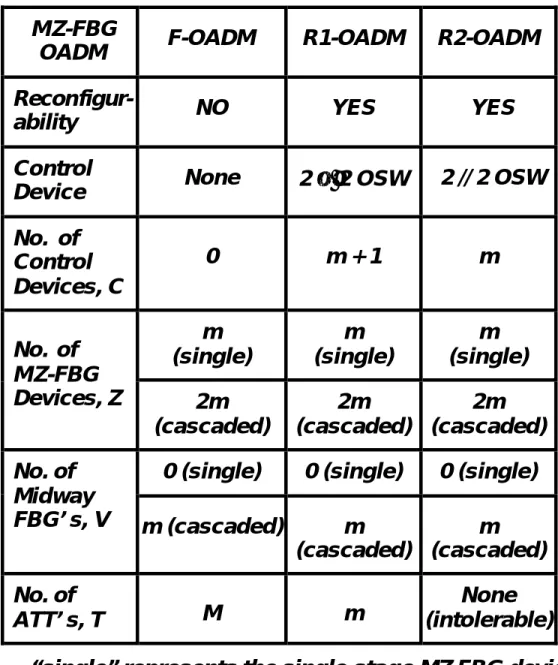
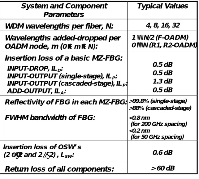
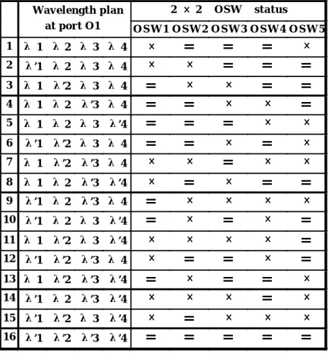
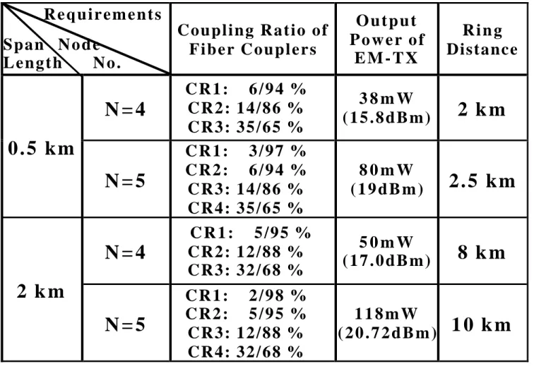
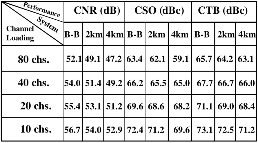
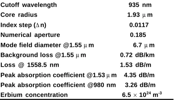
(10) List of Tables Page Table 3.1: Required constitutive elements for the proposed three MZ-FBG-based optical add-drop multiplexers (OADM’s): the fixed OADM (F-OADM), and the first and second types of reconfigurable R1-OADM and R2-OADM. ....................................................... 78 Table 3.2: System parameters and component cha racteristics with their typical values used for comparison of the MZ-FBG-based OADM’s. .................................................... 79 Table 3.3: Calculated SIL and ∆SIL for the fixed F-OADM using single-stage MZ-FBG’s without (w/o) and with (w/i) optical attenuators (ATT’s) to separately add-drop a single wavelength (m = 1) and all wavelengths (m = N). ........................................................... 80 Table 3.4: The wavelength plan at output port O1 and the required operation status for both upper and bottom OSWS of the proposed 2 × 2 dynamic OXC. . . .......................... 81 Table 4.1:The coupling ratio of each fiber coupler and the required EM-TX output power for implementing the four- and five- node MMF-LANs with 0.5-km and 2-km spans. .... 82 Table 4.2: The worst CNR, CSO, and CTB of back-to-back (B-B), 2-km, and 4-km MMF transmission cases for different loading channels. … … … … … … … … … … … … … … … 8 3 Table 5.1: Nine kinds of H-WDM EDFA configurations, their compositions using the related blocks, and their configuration symbols. … … … … … … … … … … … … . … … … . 84 Table 5.2: Characteristics of erbium-doped fiber used in this work. … … … … … … … … 8 5 Table 5.3: EDFA simulation parameters used in this work. … … … … … … … … … … … 8 6. viii.
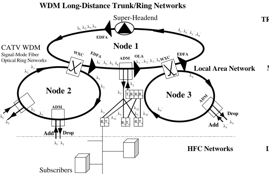
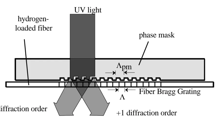
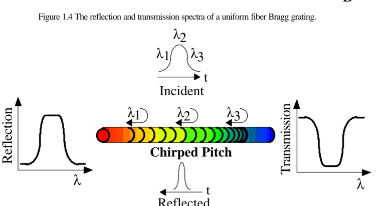
(11) List of Figures Page Figure 1.1 A WDM of multi-channel point-to-point fiber link. … … … … … … … … . . . … . 8 7. Figure 1.2 Architecture of WDM long-distance Trunk and Ring Networks. … … … … . . . 8 8. Figure 1.3 Phase mask technique for writing fiber grating. … … … … … … … . . … … … … 8 9. Figure 1.4 The reflection and transmission spectra of a uniform fiber Bragg grating. … … … … … … … … … … … … … … … … … … … … … … … … … … … … . … . . … … 9 0. Figure 1.5 A schematic diagram of a chirped fiber Bragg grating. … … … … … … … . . . … 9 0. Figure 1.6 A schematic diagram of Mach-Zehnder fiber Bragg grating. . … … … . . … … . . . 9 1. Figure 1.7(a) A typical erbium-doped fiber amplifier and (b) The gain and absorption spectra for erbium-doped fiber. … … … … … … … … … … … … … … … … … … … … ... …..92. Figure 1.8 The Raman gain profile of silica fiber. … … … … … … … … … … … … … . . . … . 9 3. Figure 2.1 A point-to-point OADM in DWDM transmission system. … … … … … . . … … 9 4. Figure 2.2 A basic OADM functions of AWG. … … … … … … … … . . … … … … . … … … . 95. Figure 3.1 Structures of (a) the conventional OADM, (b) the first and second proposed MOC-based OADMs, and (c) the third proposed MOC-based OADM. … … … … … . … .96. Figure 3.2 Experimental setup. … … … … … … … … … … … … … … … … … … … . . … … … 9 7. Figure 3.3 Output spectra of the dropped channel in (a) M(i)-type and (b) M(iii)-type OADMs. … … … … … … … … … … … … … … … … … … … … … … … … … … … … . . … … . . 9 8. Figure 3.4 Output spectra of the added channel in (a) M(i)-type and (b) M(iii)-type OADMs. … … … … … … … … … … … … … … … … … … … … … … … … … … … … . . . … … . . 9 9. ix.
(12) Figure 3.5 The intra-band crosstalk levels and power penalty of both 1554.13-nm dropped and added channels in these four OADM structures. … … … … … … … … … … . … . … … 1 0 0. Figure 3.6 Schematic diagrams of (a) the single-stage MZ-FBG device, and (b) the cascaded- stage MZ- FBG device for constructing both fixed and reconfigurable OADM’s. . … … … … … … … … … … … … … … … … … … … … … … … … … … … … . …...101. Figure 3.7 Schematic diagram of the proposed MZ-FBG-based polarization- insensitive fixed OADM (F-OADM). … … … … … … … … … … … … … … … … … … … . … . . … … … 1 0 2. Figure 3.8 Proposed first type of reconfigurable OADM (R1-OADM). … … … … … … 103. Figure 3.9 Proposed second type of reconfigurable OADM (R2-OADM). … … . . . … … . 1 0 4. Figure 3.10 The numbers of required MZ-FBG devices, midway FBG’s, and OSW’s for the reconfigurable R1-OADM and R2- OADM as a function of number of the added-dropped wavelengths, m. … … … … … … … … … … … . . … … … … … … … … … .105 Figure 3.11 The worst SIL and ∆SIL for the fixed F-OADM’s as a function of the number of added-dropped wavelengths, m. The maximum SIL and ∆SIL allowed are assumed to be 30 and 20 dB, respectively. … … … … … … … … … … … … … … … … … … … … … … .106. Figure 3.12 The worst SIL for the reconfigurable R1-OADM’s and R2-OADM’s as a function of the number of added-dropped wavelengths, m. The maximum SIL allowed is assumed to be 30 dB. … … … … … … … … … … … … … … … … … … … … … … … … ..….107 Figure 3.13 The worst ∆SIL for the reconfigurable R1-OADM’s and R2-OADM’s as a function of the number of added-dropped wavelengths, m. The maximum ∆SIL allowed is assumed to be 20 dB. … … … … … … … … … … … … … … … … … … … … … … … . . … … 1 0 8. x.
(13) Figure 3.14 Relations between the system power penalty induced separatelyby the interband and intraband crosstalk versus crosstalk level. … … … … … … … … … … … … 109. Figure 3.15 Calculated spectral response of 1, 3, 6, 10, 18, and 30 single-staged OADM’s in series to show bandwidth narrowing for the apodized Gaussian MZ-FBG-based OADM’s. The single-OADM 3-dB bandwidth was 50 GHz. … … … … … … … … … ...110 Figure 3.16 Proposed MZ-FBG-based 2 × 2 dynamic OXC and the experimental setup. … … … … … … … … … … … … … … … … … … … … … … … … … . . . … … … … … … 111 Figure 3.17 Output spectra of the 2 × 2 OXC at (a) port O1 and (b) port O2 while activating both MZ-FBG1 and MZ-FBG3. … … … … … … … … … … … … . … … … … … 112 Figure 3.18 The BER performance of the cross-connected channel λ’1 at O1-port and channel λ1 at O2-port for the back-to-back (B-B, 0 km), without intra-band crosstalk (OSWα off), and with intra-band crosstalk (OSWα on) cases. … … … . … … … … … … .113 Figure 3.19 Calculated SIL and ∆SIL characteristics and simulated intra- band crosstalk- induced power penalty (δP) of the 2×2 OXC for each MZ-FBG separately with reflectivity of R1 = 99.8% and R2 = 99.953%. … … … … … … … … … … … … … … … 1 14 Figure 4.1 The proposed four-node LAN ring configuration for simultaneously delivering the 1.55-µm CATV video signal and the 1.3-µm data signal. … … … … … … … … … … .115. Figure 4.2 The experimental setup for feasibility demonstration. … … … . 116. Figure 4.3 System performance of CNR, CSO, and CTB for 2- km and 4-km systems versus channel frequencies with 80-channel loading. … … … … … … … .117. Figure 4.4 Measured BER of the back- to-back (B- B), 2-km, and 4- km systems with/without AM-VSB video delivery. Inset: the received eye diagram of 155 Mb/s data signal of the 4-km MMF system. … … … … … … … … … … … … … … … … … … … … … 118. xi.
(14) Figure 4.5 Experimental setup of repeaterless bi- directional WDM transmission system. … … … … … … … … … … … … … … … … … … … … … … . … … … … … … … … … 119. Figure 4.6 Optical spectra of the 50-km SMF link (a) at port 3 of OC2 (indicated as C), (b) at the output port of OBPF2 (indicated as D), and (c) at the output port of MUX2 (indicated as E). … … … … … … … … … … … … … … … … … … … … … … … … … … … ...120. Figure 4.7 Measured CNR, CSO, and CTB of the system with MUX and OC configurations after 50-km transmission. … … … … … … … … … … … … … … … … … … 121. Figure 4.8 Experimental setup. … … … … … … … … … … … … … … … . . … … … … … … . 1 2 2. Figure 4.9 The optical spectra of 100-km SMF system (a) at the port 3 of OC1 (position A) for in- line amplifier without OBPFs, and (b) at the output port of OBPF1 (position B) when the in- line amplifier with insertion of OBPF1 and OBPF2. … … … … … … … … … … … … … … … … … … … … … … … … … … … … … … … 123. F i g u r e 4 . 1 0 T h e m e a s u r e d C N R , C S O , a n d C T B o f t h e A M - VSB channels. … … … … … … … … … … … … … … … … … … … … … … … … … … … … … … .124. Figure 5.1 The HFC or FTTC/FTTH trunk and access lightwave system, in which the block diagram of various 980- nm-pumped H-WDM EDFA configurations with associated optical components as shown in the insets are used to simultaneously amplify hybrid digital/analog WDM signals. … … … … … … … … … … … … … … … … … … … … … … .125. Figure 5.2 Optical channel allocation of the H-WDM signals and notation of related system parameters. … … … … … … … … … … … … … … … … … … … … … … … … … … .126 Figure 5.3 Optimal EDF length and corresponding differential channel output power ∆PD for various amplifier configurations against the digital channel spacing ∆λD of 1.6, 0.8, and 0.4 nm. … … … … … … … … … … … … … … … … … … … … … … … … … … … … … .127. Figure 5.4 Output power and noise figure characteristics of both the analog channel at 1558.17 nm and the digital channel at 1551.72 nm for various amplifier configurations xii.
(15) operated with ∆λD of 0.8 nm. … … … … … … … … … … … … … … … … … … … … … … .128. Figure 5.5 The optical spectral (a) gain and (b) noise figure characteristics of four amplifier configurations without using the midway optical isolator versus the 0.8-nm-spacing channel wavelengths. … … … … … … … … … … … … … … … … … … … .129. Figure 5.6 The optical spectral (a) gain and (b) noise figure characteristics of five amplifier configurations with a midway optical isolator in EDFA versus the 0.8-nm-spacing channel wavelengths. … … … … … … … … … … … … … . … … … … … … 130. Figure 5.7 Calculated optical output spectrum of the FB-type EDFA with a launched eleven H-WDM input signal channels, where the digital channel spacing is 0.8 nm. … … … … … … … … … … … … … … … … … … … … … … … … … … … … … … … … . 1 3 1. Figure 5.8 The effect of input signal power of each digital channel on the analog channel o u t p u t p o w e r PA and noise figure NF A characteristics of the FB- type EDFA. … … … … … … … … … … … … … … … … … … … … … … … … … … … . … … … … .132. Figure 5.9 The effect of input signal power of each digital channel on the channel output power PD,1551.72 of the FB-type EDFA for digital channel at 1551.72 nm and the differential channel output power ∆PD among digital channels. … … … … … … … … . … 133. Figure 5.10 Experimental setup. … … … … … … … … … … … … … … … … . … … … … … .134. Figure 5.11 (a) Gain spectra of SOA, Raman amplifier (RA), non-gain-clamped amplifier (SOA+RA: non-GC amp.), and gain-clamped amplifier (GC-amp.), and (b) optical gain and noise figure characteristics of non-GC amp. and GC-amp. as a function of input power. … … … … … … … … … … … … … … … … … … … … … … … … … … … … . … … … .135. F i g u r e 5 . 1 2 T h e m e a s u r e d b i t - e r r o r- r a t e c u r v e s a f t e r 1 0 0 - km SMF transmission. … … … … … … … … … … … … … … … … … . . . … … … … … … … … … … … . 1 36. xiii.
(16) List of Acronyms ∆SIL. Differential System Insertion Loss. AM-VSB. Amplitude Modulation Vestigial SideBand. APC. Angled Physical-Contact. ATTs. Optical Attenuators. AWG. Arrayed Waveguide Grating. ASE. Amplified Spontaneous Emission. B-B. Back-to-Back. BER. Bit Error Rate. BW. BandWidth. CATV. Cable Television. CFG. Chirped Fiber Grating. CNR. Carrier-to-Noise Ratio. CO. Central Office. CR. Coupler. CSO. Composite Second Order. CTB. Composite Triple Beat. DCF. Dispersion Compensated Fiber. DBF LD. Distributed-FeedBack Laser Diode. DSF. Dispersion Shifted Fiber. DWDM. Dense Wavelength Division Multiplexing. EDF. Erbium-Doped Fiber. EDFA. Erbium-Doped Fiber Amplifier. EM-TX. Externally Modulated Transmitter. FBG. Fiber Bragg Grating. FP-LD. Fabry-Perot laser diode. xiv.
(17) FRA. Fiber Raman Amplifier. FTTC. Fiber To The Curb. FTTH. Fiber To The Home. GC. Gain Clamping. HE. HeadEnd. HFC. Hybrid Fiber Coaxial. H-WDM. Hybrid Wavelength Division Multiplexing. ISO. Optical Isolator. LAN. Local Area Network. LEAF. Large Effective Area Fiber. MAN. Metropolitan Area Network. MMF. Multi-Mode Fiber. MOCs. Multi-port Optical Circulators. MSOs. Multiple System Operators. MUX/DEMUX. Multiplexer/DeMultiplexer. MZ-FBG. Mach-Zehnder Fiber Bragg Grating. NF. Noise Figure. NRZ. Non Return Zero. NTSC. National Television Standard Committee. OADMs. Optical Add Drop Multiplexers. OBPF. Optical BandPass Filter. OC. Optical Circulator. OLA. Optical Limiting Amplifier. ONU. Optical Network Unit. OSW. Optical Switch. OXC. Optical Wavelength Cross-connect. PINFET. PIN Field Effect Transistor. PRBS. Pseudo Random Bit Sequence. QAM. Quadric Amplitude Modulation. xv.
(18) RF. Radio Frequency. RIN. Relative Intensity Noise. RX. Optical Receiver. SBS. Stimulated Brillouin Scattering. SCM. Sub-Carrier Multiplexing. SDH. Synchronous Digital Hierarchy. SIL. System Insertion Loss. SMF. Single-Mode Fiber. SNR. Signal-to-Noise Ratio. SOA. Semiconductor Optical Amplifier. SONET. Synchronous Optical Network. SRS. Stimulated Raman Scattering. TX. Transmitter. VOA. Variable Optical Attenuator. WDM. Wavelength Division Multiplexing. WSC. Wavelength Selective Coupler. XGM. Cross Gain Modulation. xvi.
(19) Chapter 1 General Introduction 1.1 Brief Introduction of WDM Architectures With the unprecedented growth in telecommunication and data traffic, and the urgent demand for diverse services, the capacity increase of the transmission system is needed. Recent advances in dense wavelength-division multiplexing (DWDM) technology are expected to provide solutions to this challenge. WDM is essentially the same as frequency division multiplexing, which has been used in radio systems for more than a century. Furthermore, WDM transmission systems employing up to 40 wavelengths at 2.5 Gb/s over a single fiber are commercially available today, and system with fewer wavelengths at 10 Gb/s are becoming available. The schematic of a WDM link shown in Figure 1.1 is to transmit data simultaneously at multiple carrier wavelengths (or frequencies) over a fiber by WDM multiplexer, and then these wavelengths demultiplexed to separate the individual wavelength to its own receiver. Provided we take a look at today’s network architectures, we can find that most local and metropolitan area networks utilize very simple broadcast topologies such as point-to-point or rings. Therefore, all nodes in the network share a single channel for transmitting and receiving data. In the contrast, wide area networks use a mesh topology, with nodes having switches to forward data coming in from a node to another node. These networks not only are usually sparsely connected to reduce the link cost, but also provide spatial reuse of the network capacity. WDM network architectures can be classified into two broad categories: wavelength cross-connect architectures (WXC) and wavelength add-drop (OADM) architectures as shown in Figure 1.2. In the example shown, different nodes transmit at different wavelengths. These signals are added or dropped by a device in the middle of the network to all the nodes. In this case, the device is an optical add-drop multiplexer, which can 1.
(20) extract the desired signals (λ1 , λ2 , λ3 , λ4 ) from all the nodes and re-add the signals (λ1’, λ2’, λ3’, λ4’) on to each OADM. The number of nodes in these networks is limited because the wavelengths cannot be reused in the network, and the dimension of OADM also limited. A more sophisticated and practical architecture today is one that employs wavelength cross-connect as shown in Figure 1.2. The nodes in the network are capable of cross-connect different wavelengths at an input port to different output port. This enables us to build up many lightpaths to exchange the same wavelength in the network; that is, the system capacity can be reused spatially. Depending on the OADM and WXC functionality available at the nodes, these networks also can be classified as either fixed or reconfigurable. A fixed network does not have any desired single-and multiple-wavelength selection or switches in it. On the other hand, a reconfigurable network contains optical switches and/or wavelength converters, giving it the capability to choose any desired single-and multiple-wavelength.. 1.2 Review of Fiber Bragg Gratings The devices of fiber Bragg grating (FBG) play a very important role in fiber optic communication systems. The major applications are such as filtering, add/drop multiplexing,. gain. equalization,. laser. wavelength. stabilization,. and. dispersion. compensation for accumulated dispersion in the system. In this section, the operation principles of fiber Bragg grating will be briefly reviewed. A fiber grating is a periodic perturbation in the refractive index along the fiber by making use of the photosensitivity of certain types of optical fibers. The formation of permanent gratings in an optical fiber was first demonstrated by Hill et. al, in 1987 [1]. They launched intense argon- ion laser radiation into a germanium-doped fiber and observed an increase in the reflected light intensity. Since then, grating-writing technologies such as. phase masks have matured to produce gratings. When it is. illuminated by an ultraviolet light beam (248 nm) shown in Figure 1.3, it splits the beams into different ±1 diffractive orders, which then interfere with one another to write the grating into the fiber. 2.
(21) The fiber gratings we will discuss in this section include uniform and chirped fiber Bragg gratings, and Mach-Zehnder fiber Bragg grating.. Uniform and Chirped Fiber Bragg Gratings For uniform and chirped FBG, the index perturbation ∆n( z ) in fiber gratings can be expressed as 2π ∆ n( z) = ∆ n 0 ( z ) 1 + m cos z Λ . (1.1). Where z is the position along the grating, ∆n0 (z) is the maximum index modulation, and m is the contrast number (which is determined by the visibility of the UV fringe pattern). The strongest constructive interaction occurs at the Bragg wavelength λB , which is given by. λ B = 2neff Λ. (1.2). Where neff is the effective core index of refraction over a spatial average of n(z) and Λ is the uniform grating pitch. Since constructive interference occurs in the back-reflected wave, the grating will only reflect the spectral component that matches (1.2) but does nothing to the remaining components of the incident light, which provides the filter characteristic shown in Figure 1.4. If the grating pitch Λ(z) is not a constant but a monotonically increasing or decreasing function, the grating is called a chirped grating that reflects different wavelengths at different positions along it. The Bragg condition in a chirped grating will then be modified as. λ B ( z ) = 2neff ( z ) Λ( z ). (1.3). If λB(z) varies linearly as a function of position over the grating, such a grating is called a linearly chirped fiber Bragg grating. With this characteristic, different frequency components of an incident light are reflected at different points, depending on where the Bragg condition is satisfied locally. From Figure 1.5, it is easy to understand the operation of a chirped FBG. For conventional single- mode fiber with positive dispersion at the wavelength of 1.55-µm region, the short-wavelength (high- frequency) components of an 3.
(22) optical pulse propagate faster than the long-wavelength (low-frequency) components. The short-wavelength needs to travel further into the grating before being reflected and thus experiences more time delay than long-wavelength components. As a result, the grating induced time delay should be opposite to the fiber dispersion. The grating- induced dispersion Dg (ps/nm) can be determined by. Dg =. τg ∆λ. =. 2neff Lg c∆λ. (1.4). Where Lg is the length of the FBG, ∆λ is the Bragg wavelength differential at the two ends of the grating, c is the speed of light, and τg = 2n eff Lg / c is the round-trip time inside the grating.. Mach-Zehnder Fiber Bragg Gratings 2×2 Mach-Zehnder fiber Bragg gratings as shown in Figure 1.6 consists of three stages: an initial 3-dB directional coupler that splits the input signals, two pieces of identical FBGs photo- imprinted in the two same path- length arms to act as distributed- feedback reflection mirrors, and another 3-dB coupler that recombines the signals at the output. The first 3-dB coupler splits the WDM signals launched into the INPUT port evenly. Except the Bragg-resonant wavelength (λ2 ) the rest of signals propagate along each arm to the second 3-dB coupler, where they are coherently recombined and emerge from the OUTPUT port. The signal of Bragg-resonant wavelength is reflected back by the Bragg gratings located symmetrically at the two arms. It emerges from the DROP port rather than the INPUT port, because the double π/2 phase shift arising at 3-dB coupler [3]. Owing to the symmetrical structure of the MZ-FBG, another signal of Bragg wavelength inserted from the ADD port can be guided to the OUTPUT port.. 1.3 Properties of Wideband Optical Amplifier Speaking of optical amplification, we will discuss in this section three different types of optical amplifier in fiber optic communication system, erbium-doped fiber amplifier (EDFA), semiconductor optical amplifier (SOA), and fiber Raman amplifier (FRA). 4.
(23) Erbium-doped Fiber Amplifier (EDFA) Figure 1.7(a) shows a schematic of the EDFA, consisting of basically a short length (~ 10-20 m for C-band EDFA and ~ 60-120 m for L-band EDFA) of a single- mode fiber doped with the rare-earth element erbium, the diachronic (two-wavelength) coupler, a semiconductor pump laser that excites the erbium ions to achieve population inversion, and optical isolator [4-6]. The diachronic coupler combines either 980/1550-nm or 1480/1550-nm to couple both the pump and signal into the erbium-doped fiber (EDF). The pump light can be coupled into the EDF from either its front end (co-propagating, called forward pumping scheme) or its rear end (counter-propagating, called backward pumping scheme). Pumping simultaneously from both ends (bi-directional pumping scheme) can improve both high-power and low- noise performance. Figure 1.7(b) shows a typical gain and absorption coefficient spectrum of the erbium-doped fiber with aluminum and germanium co-doped in the core [7]. EDFA has several advantages and important features. First, the wide gain bandwidth of 30 nm (1530 nm to 1560 nm for C-band EDFA, and 1570 nm to 1600 nm for L-band EDFA) can allow near 40 WDM channel signals with 0.8-nm channel spacing to be amplified simultaneously, and thus guarantee the success of WDM technology. Second, the gain of EDFA is very high around 25 to 30 dB, and can be fiber-compatible. Third, the noise figure of EDFA, defined as the degradation of signal’s signal-to-noise ratio due to the amplifier’s spontaneous emission, is typically 4-5 dB. Fourth, the long fluorescence lifetime of the excited state about 10 ms, compared with signal’s bit time, leads to slow gain fluctuation. Fifth, owing to the modulation speed faster than the response of erbium ions, EDFA is almost a “data-transparent” amplifier. Therefore, EDFA can be used as power amplifier, in- line amplifier, and pre-amplifier applications in many fiber optic communication systems.. Semiconductor Optical Amplifier (SOA) Semiconductor optical amplifier is essentially a pn-junction. Light is amplified through stimulated emission when it propagates through the active region. Signals in the 1.3 and 1.55 µm bands can be simultaneously amplified using SOAs. We see that it is not 5.
(24) as good as EDFAs to act as amplifier, because there are two major problems in using SOAs. The first is the poor noise figure of SOA (typically 6 to 10 dB) due to the large input coupling loss in the range of 2 dB (from single- mode fiber to a semiconductor waveguide) and the residual SOA facet-reflectivity- induced relative intensity noise. The second is poor SOA linearity performance owing to its short carrier lifetime (~ several hundred picoseconds), much faster than that of an EDFA. Hence the signal- induced gain modulation can result in serious intermodulation distortion in the SCM system. To alleviate the signal- induced gain modulation, the concept of gain-clamping technique by laser oscillation in an SOA has been demonstrated successfully [8, 9] in both digital and analog WDM system. The principle consists of pinning the population inversion by forcing the amplifier to oscillate at a wavelength located far away from the useful spectral gain, and thus avoid large unsaturated gain reduction. Another method to increase the SOA stimulated rate, which results in the decreased carrier lifetime, is external light injection, and consequently increases the corresponding saturation output power.. Fiber Raman Amplifier (FRA) The fiber Raman amplifier we discuss here uses silica fiber as its amplification medium for the amplification and dispersion compensation at 1.5-µm region. Since its gain efficiency is even lower than that of EDFA, it must use a high-power Nd-doped fiber laser or 1480-nm region semiconductor laser diodes with over hundreds of mW or several W output power as the pump source. The Raman phenomenon takes place at high powers in a nonlinear optical medium. It consists of an inelastic photon scattering induced by phonons of the medium. The photon-phonon interaction gives rise to the Stokes shift from the original frequency. That is, incident light at a specific frequency can generate frequency-shifted Stokes wave. When pump power exceeds a threshold value, the Stokes waves build up almost exponentially, which is so-called the stimulated Raman scattering (SRS) phenomenon. Figure 1.8 shows the Raman gain profile of silica fiber [10]. A suitable. choice. of. nonlinear. medium,. dispersion-shifted. fiber. (DSF). or. dispersion-compensated fiber (DCF), and pump frequency, 1400 to 1500-nm pump laser 6.
(25) diode, can give a power of pump frequency shift (about 108 nm or 13.2 THz) to that of the signals at 1.5- to 1.6-µm region to be amplified. In generally speaking, the successful demonstration of 75nm Raman amplification using two spans of about 5km DCF and a total pump power of 2 W at 1420 nm and 1470 nm had been reported recently [11].. 1.4 The Dissertation Organization There are six chapters organized in this dissertation. Chapter 2 describes the overview and motivation of these three application areas, and then proposes our system applications for WDM Long-Distance Trunk/Ring Networks. In Chapter 3, we address the designs of FBG-based optical add-drop multiplexing (OADM) system for DWDM networks, inclusive of using a multi-port circulator and FBGs for low-crosstalk and compact OADMs, and MZ-FBG-based fixed and reconfigurable multi-channel OADMs. Such MZ-OADMs not only can add and drop either single or multiple wavelengths, but also need no additional WDM demultiplexers and multiplexers. We also discuss the designs of fiber Bragg grating (FBG)-based optical cross-connect (OXC) multiplexing system, especially a modified series-type architecture using Mach-Zehnder (MZ) FBGs in combination with 2×2 optical switches (OSWs). In Chapter 4, we propose simultaneous video and data signals transmission system over multi- mode fiber local area network (MMF-LAN), and the bi-directional transmission systems of multiple amplitude modulation vestigial sideband (AM-VSB) CATV signals, including a repeaterless bi-directional transmission system over 50-km single- mode fiber (SMF), and a bi-directional 100-km SMF and large effective area fiber (LEAF) transmission system. In Chapter 5, we simulate and demonstrate the optimum configuration and characteristic comparisons of wideband optical amplifier for DWDM system applications. Various configurations of erbium-doped fiber amplifier (EDFA) for simultaneously amplifying AM-VSB analog CATV signal and multiple optical digital baseband signals in hybrid wavelength division multiplexing (H-WDM) systems are proposed. Furthermore, the demonstration of such wideband amplifier not only carries out dispersion 7.
(26) compensation of the SMF spans, but also offers a good gain flatness of amplification. The nonlinear effect and improved approach within the semiconductor optical amplifier (SOA) are also addressed. Chapter 6 gives a brief conclusion of this work and research.. 8.
(27) Chapter 2 Overview and Motivation This chapter will describe the overview and motivation in three concern applications: 1) fiber Bragg grating-based OADM systems for WDM Long-Distance Trunk/Ring Networks, 2) multiple AM-VSB signals transmission systems, and 3) wideband optical amplifiers for metropolitan area network as shown in Figure 1.2.. 2.1 Fiber Bragg Grating-Based OADM Systems The dense wavelength-division- multiplexing (DWDM) technique combining with erbium-doped fiber amplifiers (EDFA’s) has shown its capability to cost-effectively, gracefully upgrade the capacity of embedded long-distance transmission systems operating in the 1550-nm wavelength region [12]. The extensive deployments of such WDM amplified point-to-point transmission systems and/or SONET/SDH ring networks open the perspective of efficiently performing network functions in the optical domain. Thus, new optical elements are required to provide additional facilities for WDM signals locally transmitting/extraction (i.e., the add/drop operation), for signal routing and network (re)configuration (i.e., the cross-connect operation) in such DWDM networks. Optical add-drop multiplexer (OADM) and optical cross-connect (OXC), two of the new network elements, will play a key role enabling greater connectivity and flexibility in DWDM networks [13-15]. The importance of OADM’s and OXC’s is that they allow the optical network to transmit/extract and exchange on a wavelength-by-wavelength basis to optimize traffic, efficient network utilization, network growth, and to enhance network flexibility.. 9.
(28) 2.1.1 Low-Crosstalk and Compact Optical Add-Drop Multiplexer Based on A Multi-Port Circulator and Fiber Bragg Grating Among FBG-based OADMs, the conventional structure using FBGs sandwiched between a pair of three-port optical circulators [16] is the simplest one. Such structure has been demonstrated over an installed 4 × 2.5 Gb/s optically amplified submarine cable system [17]. Recently, multi-port optical circulators (MOCs) with port number of ≥ 6 are commercially available and are promising for many applications to miniaturize the dimension of fiber-optic device due to the compactness of such MOC. Therefore, we propose and demonstrate three kinds of new and compact OADM structures based on using an MOC with FBGs. The intra-band interferometric crosstalk, which results from the insufficient reflectivity of the used FBG, can be hugely reduced by such MOC-based structure with cascaded FBGs. Bit-error-rate (BER) performance and power penalty, induced by intra-band and inter-band crosstalks, of these OADMs are examined and compared in a 10 Gb/s system demonstration.. 2.1.2. Mach-Zehnder. Fiber. Bragg. Grating-based. Fixed. and. Reconfigurable Optical Add-Drop Multiplexers From the viewpoint of wavelength selecting capability, OADM’s can be classified into fixed and reconfigurable configurations. The basic operation for a fixed OADM is that it can only add and drop the desired single or multiple wavelengths in a pre-assigned pattern at each optical node. So, a fixed OADM does not have any automated wavelength selecting capability. If an OADM is non-reconfigurable, then it may be obsolete or should be modified when the network grows with more WDM channels. Many fixed OADM’s have been implemented based on different technologies such as a pair of back-to-back WDM dielectric-grating multiplexers [18], the fiber Fabry-Perot filters with optical circulators [19], arrayed waveguide grating (AWG) [20, 21], the fiber Bragg gratings (FBG’s) sandwiched between a pair of optical circulators [17, 22], Mach-Zehnder-based (MZ) FBG’s [23, 24], MZ-based grating on silica [25], and FBG’s photoimprinting upon. 10.
(29) the 3-dB coupler [26]. For the reconfigurable OADM’s, it can add and drop either single or multiple wavelength channels dynamically at each optical node according to the network’s management. Therefore they offer more flexibility for efficient network utilization and customer control and management in DWDM networks. Several reconfigurable OADM’s have been proposed and demonstrated recently. One was implemented by using a pair of N × N AWG sandwiched between a pair of 1 × N mechanical optical switch (OSW) [27], and another one was realized by actively controlling the MZ-based FBG filter [28]. However, both of them only can only add-drop a single wavelength. For reconfigurably add-dropping either single or multiple desired wavelengths, some OADM’s were realized by introduction of OSW’s in such OADM architectures. For example, one was implemented by inserting the 2 × 2 mechanical OSW within each optical path of a pair of AWG multiplexers [29, 30], or by fabricating the thermo-optic switches in between the silica-based AWG multiplexers [31]. Some OADM’s were realized by introduction of OSW’s in the parallel [32] or series [33] FBG-based architectures. On the other hand, the acousto-optic tunable filter has also been shown the capability for acting as a reconfigurable OADM with its fast µs-switching speed but with undesired side lobes [34]. However, for these OADM’s reported in [35-38], additional WDM demultiplexer and multiplexer are required at the drop and add ports, respectively, to implement full add-drop functionality. This drawback makes them unpractical and expensive to be used. Recently, an InP-based OADM [39] consisting of a loop-back AWG demultiplexer integrated with MZ interferometer electro-optic switches has been demonstrated without the need of additional WDM multiplexer and multiplexer. However, the poor features of high intraband crosstalk of –20 dB, high on-chip insertion loss of 7-11 dB, and polarization-sensitive property imply that more improvements are required for such device to be capable of add-dropping multiple WDM channels. With the motivation of investigating both fixed and reconfigurable polarization- insensitive OADM’s, we first, to the best of our knowledge, utilize the Mach-Zehnder fiber Bragg grating-based (MZ-FBG) [40] devices with the associated mechanical OSW’s to construct large-dimension OADM’s without the needs of additional WDM demultiplexers and multiplexers. 11.
(30) 2.1.3 Mach-Zehnder Fiber Bragg Grating-Based Dynamic Optical Cross-Connect Fiber Bragg grating (FBG) as a cross-connecting element in OXCs is very attractive recently [41]. On the other hand, the FBG-based Mach-Zehnder Interferometer (MZ-FBGs) device [42] has sho wn its capability for optical add-drop multiplexers. Recently, a dynamic 2 × 2 OXC employing MZ-FBGs and optical space switches (OSWs) was reported [43]. However, the number of required MZ-FBGs in this structure is too large, due to the used parallel-type architecture, to limit its usage for practical application. A series-type 2 × 2 MZ-FBG-based OXC was reported [44]. It has strictly non-blocking operation at the expense of serious circulated and accumulated high-order intra-band crosstalks accompanied with basic intra-band crosstalks. These crosstalks limit its performance. Therefore, we propose a modified series-type architecture using MZ-FBGs in combination with 2 × 2 OSWs for constructing a rearrangeably non-blocking 2 ×2 OXC with not only a huge reduction of four order of required MZ-FBGs as compared with the work in [44], but also eliminating the circulated and accumulated high-order intra-band crosstalks as compared with the work in [44]. Dynamic single- and multi- channel cross-connections can be realized according to the control of OSW arrangements. Network demonstration and bit-error-rate (BER) performance of the proposed OXC are examined. The loss and crosstalk characteristics of the OXC, and thus the allowable number of DWDM channels are investigated.. 2.2 Multiple AM-VSB Signals Transmission Systems A combination of EDFA and WADM technology can provide unprecedented ability to expand transmission capacity in long-distance transmission systems or local area networks. Bi-directional transmission over a single fiber can further double the transmission capacity. However, the amplified spontaneous emission (ASE) of EDFA, crosstalk from Rayleigh backscattering, and fiber nonlinear effects in the transmission. 12.
(31) process give many constraints to system performance, especially those employing analog bi-directional transmission. In this section, we begin with simultaneous video and data signals transmission system and then propose bi-directional AM-VSB transmission links.. 2.2.1 Simultaneous Video and Data Signals Transmission System over Multi-Mode Fiber Local Area Network Delivery of AM-VSB CATV video signals through standard single- mode fiber (SMF) link using the 1.3-µm or 1.55-µm opto-electronic technology to increase the transmission distance, the number of distribution nodes, and to maintain high video quality is the trend for CATV operators in the worlds [40–44]. On the other hand, numerous high-speed lightwave local-area networks (LANs) using multi- mode fibers (MMFs) have been installed in the campus. Beside the data service, new service such as video broadcasting to buildings and classrooms is expected to implement through the existed LAN networks. However, the delivery of CATV video signals over an MMF LAN has not yet reported. The 1.55-µm video performance degraded by the intermodal dispersion of MMF and the power penalty of 1.3-µm data transmission due to the on- line video delivery are needed to study. We investigate the transmission of AM CATV video signal at 1.55-µm and the 155-Mb/s data signal at 1.3-µm simultaneously over a graded-index MMF LAN. System designs and network size for this MMF LAN are also described and investigated.. 2.2.2 Repeaterless Bi-directional Transmission of Multiple AM-VSB CATV Signals Lightwave subcarrier- multiplexed systems ha ve been widely used for cable television (CATV) networks to deliver amplitude-modulated vestigial-sideband (AM-VSB) analog video signals [50-53]. Repeaterless long distance fiber transmission systems using erbium-doped fiber amplifiers (EDFAs) have many applications, in which cases it is infeasible or impossible to have an in- line amplifier. Bi-directional transmission over a 13.
(32) single- fiber using wavelength-division- multiplexing (WDM) technique offers the advantages of capacity doubling. Several repeaterless bi-directional digital transmission systems have been reported recently [54-57], but the repeaterless bi-directional transmission of multiple AM-VSB analog signals has not yet been studied. In addition, in some countries, telecommunication operator should put out its optical cabled fiber with associated transmitters and receivers to lease to the CATV multiple system operators (MSOs) for trunk delivery of 80 channels of analog CATV signals between any two MSOs (MSO1 and MSO2) across another different CATV-operator service area. Hence, when the dummy fiber is exhausted in the fiber cable, the fiber- leased company has to face the question that is it feasible to transport multiple AM-VSB video signals bi-directionally over a single leased conventional single- mode fiber (SMF) link. Therefore, in such case, bi-directional transmission over a single- fiber using WDM technique is the simple method to solve the problem. We investigate and demonstrate bi-directional transmission of multiple AM-VSB channels over convent ional SMF. Two kinds of multiplexers, the optical circulator (OC) and the optical multiplexer (MUX) configurations, for supporting bi-directional operation are studied and compared. Extending the repeaterless bi-directional transmission distance is also addressed.. 2.2.3 Bi-directional CATV 100 km Transmission Systems When the dummy fiber is exhausted in the fiber cable, the fiber- leased company has to face the question: Is it feasible to transport multiple AM-VSB video signals bi-directionally over a single leased fiber link? Therefore, in such case, bi-directional transmission over a single- fiber is a simple method to solve the problem. In this sub-section, we demonstrate bi-directional transmission of multiple AM-VSB channels over 100-km fiber link. The conventional single- mode fiber (SMF) and large effective area fiber (LEAF) were acted as the leased fiber link separately for comparison.. 14.
(33) 2.3 Wideband Optical Amplifier for Metropolitan Area Network With the unprecedented growth of Internet network, many large capacity WDM transmission experiments with aggregate capacities of hundreds of Gb/s or Tb/s have been demonstrated using several types of wideband optical amplifiers. The gain bandwidths of EDFAs have been enlarged through the use of gain-equalizing filters, new host materials (fluoride and tellurite glasses), and two gain band configurations [58, 59] in the 1.5- to 1.6-µm region. In this section, we investigate the configurations and amplification characteristics of wideband optical amplifier.. 2.3.1 Erbium-Doped Fiber Amplifier for Hybrid WDM Systems The implementation of Hybrid WDM systems with different signal formats is still a challenge, especially for long-distance applications using erbium-doped fiber amplifiers (EDFA’s) [60]. Because different signal formats require different sensitivities for a given quality of service, for example, around 0 dBm for AM-VSB SCM signal and about –30 and –20 dBm, respectively, for an STM-16 (2.5 Gbit/s) and STM-64 (10 Gbit/s) SONET/SDH signals. Due to the difference in the required sensitivity among the various signal formats, the optical signal levels in such systems can vary greatly, up to several tens of decibels. In a typical H-WDM system employing in- line EDFA’s for AM-VSB/QAM and baseband digital signal trans missions, the input power to the EDFA for the analog channel needs to be greater than 0 dBm to operate the EDFA in deep saturation, owing to the stringent system carrier-to-noise ratio (CNR) requirement. In contrast, the input power for the digital channels is usually less than –10 dBm due to the low output power used in digital lightwave transmitters. Here we theoretically investigate and compare various EDFA configurations to simultaneously amplify hybrid digital/analog WDM signals. The configurations considered include single-stage and two-stage designs in dual- forward, dual-backward, and various bi-directional pumping schemes, each with and without the midway optical isolator. For bi-directional pumping case, the pump-power passed and un-passed. 15.
(34) arrangements are also considered. For the two-stage design with the midway isolator cases, the optimum position and the isolation effect of midway isolator on EDFA performance are studied. A total of nine EDFA configurations are examined and compared. The investigation result provides the best EDFA configuration to design both power and in-line amplifiers for hybrid WDM lightwave systems.. 2.3.2 Dispersion-Compensated Gain-Clamped 90 nm Wideband Optical Amplifier The wideband optical amplifier through the combination of Raman amplifier (RA) and erbium-doped fiber amplifier (EDFA’s) as well as parallel configurations for the three gain-bands of the EDFA’s have been intensively studied for increasing the long- haul transmission capacity in the 1.5-1.6 µm region [61, 62]. On the other hand, the semiconductor optical amplifier (SOA) is promising for in- line amplification of DWDM transmission [63, 64]. However, those experiments have not yet utilized the full gain bandwidth of the SOA to effectively satisfy the urgent need of bandwidth for future metropolitan area network. In order to utilize the full gain bandwidth of the SOA, we demonstrate a dispersion-compensated gain-clamped wideband (1500-1590 nm) optical amplifier employing a dispersion-compensated- fiber (DCF) based Raman amplifier (RA) and an SOA for wideband amplification with good gain flatness (of 3 dB) as well as dispersion compensation of 10 Gb/s DWDM signals over a 100-km single- mode fiber (SMF) link. The amplifier design and its system performance are described.. 16.
(35) Chapter 3 Fiber Bragg Grating-Based Optical Add-Drop Multiplexing and Cross-Connect Systems This chapter investigates fiber Bragg grating-based optical add-drop and cross-connect multiplexing systems for WDM long-distance Trunk and Ring Networks. They are the systems: 1) low-crosstalk and compact optical add-drop multiplexer using a multiport circulator and fiber Bragg gratings [65], 2) Mach-Zehnder fiber Bragg grating-based fixed and reconfigurable multi- channel optical add-drop multiplexers for DWDM networks [66], 3) Mach-Zehnder fiber Bragg grating-based dynamic optical cross-connect [67], respectively.. 3.1 Low-Crosstalk and Compact Optical Add-Drop Multiplexer Using a Multi-Port Circulator and Fiber Bragg Gratings Three kinds of low interferometric-crosstalk optical add-drop multiplexers (OADMs) based on a multiport optical circulator (MOC) with fiber Bragg gratings are proposed and demonstrated [65]. There is a huge intra-band crosstalk level reduction of about 37 dB and 16 dB on the dropped and added channels, respectively, for the proposed MOC-based structure as compared with the conventional structure. Bit-error-rate performance and both intra-band and inter-band crosstalk- induced power penalties of these MOC-based OADMs are examined in a 10 Gb/s system demonstration.. 3.1.1 Optical Add-Drop Multiplexing Configurations and Experimental Setup Figure 3.1 shows the structures of (a) the conventional OADM, (b) the first and second proposed MOC- based OADMs, and (c) the third proposed MOC-based OADM. The conventional structure (hereafter C-type), consists of two three-port optical circulators (OC1 and OC2), and an FBG with central wavelength matching the ITU DWDM-channel. 17.
(36) signal, which will be dropped and added at the OADM node. In the first proposed OADM structure (hereafter, M(i)-type), a six-port optical circulator, instead of two three-port OCs, is used in combination with an FBG. The port connections arranged as indicated in Figure 3.1(b) make the add-drop operation the same as that of Figure 3.1(a). In the second proposed OADM structure (hereafter, M(ii)-type), an additional FBG with the same central wavelength is cascaded in chain to reflect the leakage light (which is due to the insufficient reflectivity) of the first FBG, and thus to reduce the intra-band crosstalk on the added channel at the output port of the OADM. In the third proposed OADM structure (hereafter, M(iii)-type), an additional FBG with the same central wavelength is placed at the fifth port of the MOC to reflect the leakage light of the first FBG. The arrangement and connection in M(iii)-type structure makes it equivalent to the M(ii)-type OADM but with a midway optical isolator in-between two FBGs. The device from port 4 and port 5 is an effective optical isolator (ISO4--5 ) in MOC as shown in Figure 3.1(c). Such arrangement of M(iii)-type structure provides the capability not only to reduce the intra-band crosstalk of the added channel at the output port, but also to block the leakage of the added channel, therefore completely reduces the intra-band crosstalk of the dropped channel. The experimental setup, as shown in Figure 3.2, consists of two sets of DWDM transmitters, an OADM, and related devices was arranged. The first transmitter set was composed of four DFB lasers with central wave lengths of 1550.92-, 1552.52-, 1554.13-, and 1555.75-nm, respectively. The second transmitter set was composed of only one DFB laser with central wavelength of 1554.13 nm, which acted as the add channel. Each transmitter set was modulated by a LiNbO3 modulator with a 231 -1 NRZ PRBS data at 10 Gb/s. A PINFET receiver (RX) with a sensitivity of –17.5 dBm at a BER of 1 × 10⁻⁹ was used. Four OADMs including the C-, M(i)-, M(ii)-, and M(iii)-type structures were examined in the experiments separately. The averaged insertion loss and optical isolation between any two ports of the MOC are about 0.9 dB and >45 dB, respectively. The transmission loss, isolation, 3-dB bandwidth, and reflectivity of each FBG are about 0.8 dB, 25 dB, 0.8 nm, and 99 %, respectively.. 18.
(37) 3.1.2 Experimental Results and Discussion Figure 3.3 shows the output spectra of the dropped channels in (a) M(i)-type and (b) M(iii)-type OADMs. The upper “dark solid ” spectrum in Figure 3.3(a) corresponds to the 1554.13-nm dropped channel in M(i)-type structure, while the lower “light thin” spectrum in Figure 3.3(a) corresponds the leakage light from the add channel. Note that the intra-band and inter-band crosstalk levels of this dropped channel are about -22 and -25 dB, respectively. Such intra-band crosstalk component of the dropped channel is due to the insufficient reflectivity of the used FBG. However, such intra-band crosstalk component can be drastically reduced as shown in Figure 3.3(b) while using the M(iii)-type OADM. The intra-band crosstalk level is now improved to about -61.5 dB. Figure 3.4 shows the output spectra of the added channels in (a) M(i)-type and (b) M(iii)-type OADMs. The intra-band crosstalk level of the added channel is about -23.9 dB. Similarly, such intra-band crosstalk component can be drastically reduced as shown in Figure 3.4(b) while using the M(iii)-type OADM. The intra-band crosstalk level is now improved to about -39.3 dB. For M(ii)-type OADM, the intra-band crosstalk level of the dropped and added channels is –54.5 and -41.5 dB, respectively. The inter-band crosstalk level of the added channel demultiplexed right after the DEMUX is the same as about -28 dB, which is limited by the 28-dB adjacent channel isolation ability of the used DEMUX, in all three OADM cases. We have measured the 10 Gb/s BER performances of both dropped and added channels operated at 1554.13 nm for these four OADM structures. Fig. 3.5 summarizes the intraband crosstalk levels and power penalty of both 1554.13-nm dropped and added channels for these four OADM structures. The power penalty in all four OADM cases is defined as the degradation of receiving sensitivity at a BER of 10-9 as compared with the baseline case without OADM. The intra-band crosstalk level of the dropped channel of the C-, M(i)-, M(ii)-, and M(iii)-type structures is -24.7, -22, -54.5, and -61.5 dB, respectively. The corresponding power penalty of the dropped channel is 0.5, 0.6, 0.4, and 0.3 dB, respectively. The 0.3-dB power penalty of the dropped channel of the M(iii)-type OADM attributes to both the signal-spontaneous beat noise, induced by the amplified spontaneous emission noise power of the EDFA, and the inter-band crosstalk because the intra-band crosstalk level of -61.5 dB can be neglected. Hence, the intra-band crosstalk- induced power penalty of the dropped channel is about 0.3, 0.1, and 0 dB for the M(i)-, M(ii)-, and 19.
(38) M(iii)-type OADMs, respectively. The inter-band crosstalk- induced power penalty can be improved by using a higher adjacent channel isolation of >40 dB of the DEMUX. On the other hand, the intra-band crosstalk level of the added channel of C-, M(i)-, M(ii)-, and M(iii)-type structures is -23, -23.9, -41.5, and -39.3 dB, respectively. The corresponding power penalty of the dropped channel is 0.6, 0.6, 0.5, and 0.5 dB, respectively. The intra-band crosstalk- induced power penalty of the dropped channel is about 0.3, 0.2, and 0.2 dB for the M(i)-, M(ii)-, and M(iii)-type OADMs, respectively. In consequence, these experimental results confirm the feasibility of the proposed MOC-based OADMs. Among them, the M(iii)-type OADM offers lower crosstalk characteristic and better system performance than those of M(i)- and M(ii)-OADMs.. 3.1.3 Summary We have demonstrated the MOC-based OADMs with fiber Bragg gratings for DWDM networks. Three kinds of MOC-based OADMs have been proposed and their add-drop operations have been investigated. Compared with the conventional structure, there is a huge reduction of the intra-band crosstalk level of about 37 dB and 16 dB for the dropped and added channels, respectively, for the proposed M(iii)-type structure. Among them, the M(iii)-type OADM offers lower interferometric crosstalk characteristics and better system performance than those of M(i)- and M(ii)-type OADMs. Satisfied BER performance and low power penalty of ≤ 0.2 dB, induced by the intra-band crosstalk, of the M(iii)-type OADM have been achieved in 10 Gb/s system demonstration. The experimental results confirm the feasibility of the proposed MOC-based OADMs. Such a low-crosstalk, miniaturized, and compact OADM may find important applications in DWDM networks.. 3.2 Mach-Zehnder Fiber Bragg Grating-based Fixed and Reconfigurable Multi-Channel Optical Add-Drop Multiplexers for DWDM Networks We first utilize the Mach- Zehnder fiber-Bragg-grating (MZ-FBG) based devices with associated optical switches to construct large-dimension OADM’s without needs of wavelength demultiplexers and multiplexers at the drop and add ports, respectively [66]. 20.
數據
+7

Outline
Dispersion-Compensated Gain-Clamped 90 nm Wideband
Low-Crosstalk and Compact Optical Add-Drop Multiplexer Using a Multi-port
Characteristic Comparison and Dimension Limits
Discussions and Summary
Experiment and Demonstration
Experimental Setup
H-WDM EDFA Configurations and Modeling
Characteristic Comparison
Dispersion-Compensated Gain-Clamped 90 nm Wideband Optical Amplifier for
相關文件
Lecture 1: Introduction and overview of supergravity Lecture 2: Conditions for unbroken supersymmetry Lecture 3: BPS black holes and branes. Lecture 4: The LLM bubbling
Lecture 1: Introduction and overview of supergravity Lecture 2: Conditions for unbroken supersymmetry Lecture 3: BPS black holes and branes.. Lecture 4: The LLM bubbling
⇔ improve some performance measure (e.g. prediction accuracy) machine learning: improving some performance measure..
“Machine Learning Foundations” free online course, and works from NTU CLLab and NTU KDDCup teams... The Learning Problem What is
Overview of a variety of business software, graphics and multimedia software, and home/personal/educational software Web applications and application software for
Certified Information Systems Security Professional (CISSP). Certified Information Systems Security
In this chapter, we have presented two task rescheduling techniques, which are based on QoS guided Min-Min algorithm, aim to reduce the makespan of grid applications in batch
Jin-Jei Wu, Daru Chen, Kun-Lin Liao, Tzong-Jer Yang, and Linfang Shen, “A novel fiber sensor based on a Bragg fiber with a defect layer”, Presented in 2009 Annular Meeting of
