The 47th JEEE International Midwest Symposium on Circuits and Systems
Area Efficient Architecture for the Embedded
Block
Coding
in JPEG 2000
Hung-Chi Fang, Yu-Wei Chang, and Liang-Gee Chen
DSP/IC Design Lab
Graduate Institute of Electronics Engineering and Department of Electrical Engineering National Taiwan University
1, Sec. 4, Roosevelt Rd., Taipei 106, Taiwan {honchi, Wayne, Igchen) @video.ee.ntu.edu.tw
Abstract- An area eficient architecture for the embedded block coding is presented in this paper. A new algorithm is proposed to compute the state variables on-the-fly. Thus, the memory for the state variables are eliminated, which occupies more than 60% area in a conventional embedded block coding architecture. The area of the proposed architecture is only of conventional architectures while the throughput is the same as others. The proposed archi- tecture has the highest performance comparing with other existing architectures according to the experimental results.
1. INTRODUCTION
JPEG 2000 [ I ] [2] [3] [4] is well-known for its excellent coding performance and numerous features [5], such as region of interest, scalability, error resilience, etc. All these power- ful tools can be provided by a unified algorithm in a single JPEG 2000 codestream. For example, an image can be loss-
lessly coded for storage and then retrieved at different bit-rates by transcoding. Transcoding of the JPEG 2000 codestream can be done by parsing, reordering, and truncating the origi- nal codestream. However, the high computational complexity that gives such excellent performance and rich features corre- spondingly restricts real-time applications of JPEG 2000. In this paper, we proposed an area efficient architecture for the embedded block coding in JPEG 2000.
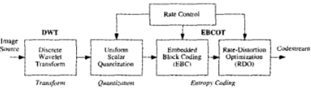
JPEG 2000 is a new still image coding standard, which is entirely different with the JPEG [6]. The functional block dia- gram of the JPEG 2000 encoder is shown in Fig. l . The Dis- crete Wavelet Transform (DWT) is adopted as the transform algorithm of JPEG 2000. The DWT has several features that are better than the Discrete Cosine Transform (DCT), such as better coding performance, easy rate control, fully embedded coding, etc. After the DWT, a uniform scalar quantization is applied to the transformed coefficient. The entropy coding al- gorithm of JPEG 2000 is the Embedded Block Coding with Optimized Truncation (EBCOT) (71 [8]. It is a two-tiered al- gorithm, in which the Embedded Block Coding (EBC) is the tier-1 and the Rate-Distortion Optimization (RDO) is the tier- 2. The EBC is based on a context-adaptive binary Arithmetic Encoder (AE). By optimized truncation of the embedded bit streams, the RDO optimizes the coded image quality at a given target bit rate.
The Embedded Block Coding (EBC) is the most complicated part of JPEG 2000 [9] and is the bottleneck for real-time appli- cations. Therefore, many EBC architectures are proposed [9] [IO] [I 11 [I21 to solve the problem. Lian et al. [9] proposed the first EBC architecture, which implements the default mode of the EBC algorithm. In this architecture, three techniques are used to skip unnecessary check-point, and the processing cy- cles are reduced by 60% comparing to [2]. To reduce the hard- ware cost, Hsiao et al. [IO] proposed a memory-saving archi- tecture that reduces the memory requirement by 4 Kbits (Kb).
Fig. I . Functional block diagram of the JPEG Zoo0 encoder. The JPEG ZOO0 encoder comprises the discrete wavelet transform, the uniform scalar quantiza- tion, and the embedded block coding with optimization truncation algorithm. On the other hand, Chiang et al. [ 1 11 proposed a pass-parallel architecture to increase the processing rate based on the parallel mode. The processing cycles are reduced by 67% comparing to [2]. The above three architectures process a code-block bit- plane by bit-plane. Fang et al. proposed a parallel architecture to process a coefficient per cycle. All the above architectures occupies more than 5.0 mm2 silicon area in 0.35 prn technology, which is too large.
In this paper, we proposed an area efficient EBC architecture for JPEG 2000. This architecture is based on the new context formation algorithm, which can accomplish the context forma- tion without storing any state variables. All the state variables are computed on-the-fly while a coefficient is read. Besides, the dataflow and controls are simplified by using the proposed algorithm. This architecture can encode all the three coding passes in a bit-plane in one scan. Therefore, it features high throughput and low area cost for the embedded block coding in JPEG 2000.
This paper is organized as follows. The proposed context for- mation algorithm is shown in Section 11. Section 111. describes the proposed area efficient EBC architecture. Experimental re- sults and comparisons are shown in Section IV. Finally, Sec- tion V. concludes this paper.
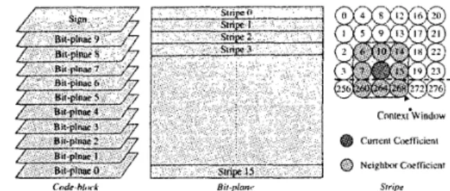
11. PROPOSED CONTEXT FORMATION ALGORITHM In this section, context formation without storing state vari- ables is proposed. Before introducing the proposed context for- mation method, let's briefly review the embedded block coding algorithm. A code-block is sign-magnitude represented for the embedded block coding, as shown in Fig. 2. The magnitude bit- planes are encoded from the Most Significant Bit (MSB) bit- plane of the code-block to the Least Significant Bit (LSB) bit- plane. A bit-plane comprises three coding passes: significant propagation pass (Pass l), magnitude refinement pass (Pass 2), and cleanup pass (Pass 3). Within a coding pass, sample coeffi- cients are divided into stripes, whose height is fixed at four and the width is equal to the code-block width. To code a sample coefficient, the sample coefficients in a 3x3 window, which is called a context window, are involved. The coding statuses of current and neighbor sample coefficients are used to generate
0-7803-8346-X/04/$20.00 02004 IEEE
Fig. 2. Decomposition of a code-block and scan order within a code-block.
A 3 x 3 context window is involved for the context formation of a sample coefficient.
TABLE I
CODING PASS CLASSIFICATION Coding Pass Condition
Pass 1
Pass 2 Significant sample Pass 3
Insignificant sample with at least one significant neighbor
Insignificant sample with all insignifi- cant neighbors
the context for the Arithmetic Encoder (AE). Two state vari- ables, U and y , are defined to summarize the coding status of a
sample coefficient. The U indicates whether a non-zero bit of
the coefficient is coded in previous bit-plane. A sample coeffi- cient is said to be significant if its U equals to one; otherwise,
it’s insignificant. The y indicates whether a sample coefficient just becomes significant in latest bit-plane. The conditions to classify a sample coefficient into one of the three coding passes are shown in Table I.
A. State Variable Computation
fine a new state variable,
ek,
asLet p denotes the magnitude of a sample coefficient, we de-
d‘
=101
>> ( k+
l)), (1) where k denotes the bit-plane number. Equation ( 1 ) checks whetherp has at least one non-zero bit at bit-planes higher than k. Thus,ek
is the significant state after the (k+l)-th bit-plane is processed. Since the significant state is updated whenever a sample coefficient is coded, 8k is not always the same as uk.Fortunately, there is only one case that the significant state of the sample coefficient is changed, which occurs when the MSB of the sample coefficient lies in the current bit-plane. To get more insight into this problem, let’s see an example. In the following discussion, c is used to denote the current sample coefficient and s is used to denote any neighbor of c for sake of simplicity. Referring to Fig. 2, if s in position 15 becomes significant in the current bit-plane, u , ~ will change to 1 (Be- ing significant) when s is coded. The question is whether U ,
changes before the coding of c or not. If s belongs to Pass 1
and c belongs to Pass 2 or Pass 3, the new U , must be used since s is coded before c (Recall that the coding order is Pass 1,
Pass 2, and then Pass 3). In other situations, is used. The same analysis can be applied to other combinations of s and c in the context widow. As a result of above analyses, the cod- ing pass of the MSB of a sample coefficient is defined as a new state variable in the proposed algorithm. This state variable is
denoted by p, which equals to one if the MSB of the sample coefficient belongs to Pass 1 and zero if the MSB belongs to Pass 3. As for the third state variable, y k , it can be computed by
r”
= $&(-ek+l).
( 2 )Note that Bk+l can be obtained by (1).
B. Coding Pass ClassiJcation
Since all the sample coefficients of a bit-plane are coded in one scan in the proposed algorithm, the sample coefficient must be first classified into one of the three coding passes. The cod- ing pass of c depends on @, and the contributions of its neigh- bors. For the neighbor, s, scanned before c, its contribution,
4
:,
is
where k is the current bit-plane and p $ is the bit value of ps
at bit-plane k. The contribution of s scanned after c is
a%,
i.e. 4% =e.
The coding pass, P:, of c is obtained by4:
= @-5I@.&p5>, ( 3 )@ = I
P: =
i
3,::
(e:
= O)&(V@t = 0 ) . (4) OtherwiseC. SigniJcant Contribution Computation
In this section, we will show how to use the three state vari- ables and the coding pass of c to compute the significant contri- bution of s for the context formation. I f s is already significant at the time that c is coded, it is said to contribute to e. The significant contributions from all the neighbors in the context window is used for the context formation of c . For s scanned before c, its contribution is
I f s is scanned after c, the contribution is
111. PROPOSED ARCHITECTURE
In this section, a low cost Embedded Block Coding (EBC) architecture is proposed. The block diagram of the architecture is shown in Fig. 3. It contains four main modules: the Context Formation (CF) module, the First-In First-Out (FIFO) module, the Arithmetic Encoder (AE) module, and the Output Buffer (OB) module. The input is the wavelet coefficient and the out- put is the embedded bit stream. The OB module is used to reduce the number of output ports while maintaining the same throughput. To prevent the buffer overflow, the number of the registers are chosen as 7.
A. Context Formation
Based on the algorithm proposed in Sec. II., a low cost CF module is obtained as shown in Fig. 4. The B k and yk are com- puted on-the-fly while reading the wavelet coefficient. The two state variables,
&-
and y k , as well as sign and magnitude bit (pk) are fed into the 2D shift registers to fit the scan order defined in the JPEG 2000 standard. The MSB coding pass, p , is then generated by the MSB pass generator, and merged into the data flow in the 2D shift registers. Therefore, each register in theCount
-
Valid.I
Fig. 3. Block diagram of the proposed EBC architecture. There are three major modules: the context formation module, the FIFO module, and the arithmetic encoder.
W.n Coeft
Fig. 4. Block diagram of the context formation module. A 2D shift register bank is used to fit the dataflow with the scan order defined in the JPEG 2000 encoder.
2D shift registers has five bits. Although only three columns of stripe are involved in a context window, four columns of stripe are required in the proposed architecture since the MSB pass generator is one column ahead of the context formation. Be- sides, a line buffer with size 64 x 5 is required to store the last row of previous stripe. The eight neighbors in the context win- dow are fed into the MSB pass generator. For a neighbor s,
C;, p s , and p: are the required information for the MSB pass generator as defined in (3).
The coding pass and significant contributions are generated in the pass & contribution generator for the context formation. In order to cope with the special run-length code, the contexts generated by the zero coding, magnitude refinement, and sign coding modules are buffered for three cycles. After deciding whether the run-length code is used or not, the final CXD pairs are generated by the run length coding module. Note that var-
ious number of Context Decision (CXD) pairs may output in one cycle. The extreme case occurs in the first sample coeffi- cient of a column when the run-length coding fails. Four CXD pairs are generated in this case: one run-length CXD pair, two uniform CXD pairs, and one sign coding CXD pair. The coding pass information is also required since the three coding passes are processed in parallel.
B. FIFO
The FIFO module is used to smoothen the input data flow of the AE module. This is because the CF module generates vari- ous number of CXD pairs, from 0 to 4, per cycle. However, the AE module can only process one CXD pari per cycle. Thus, the use of the FIFO module can alleviate the problem arisen from the throughput mismatch between the CF and AE modules. As shown in Fig. 5, there are four registers in the FIFO, in which each register has seven bits comprising two bits of coding pass and five bits of CXD pair.
Fig. 5. Block diagram of the FIFO module. There will be 0
-
4 inputs and one output per cycle.c
4
c c
Fig. 6. Block diagram of the.AE module. It has three suits of the coding status registers and one suit of processing elements.
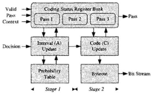
C. Arithmetic Encoder
In the proposed architecture, the three coding passes in a bit- plane is proposed in parallel. Thus, there are three embedded bit streams to be processed by the AE in parallel. Therefore, the Pass Switching AE (PSAE) [ 111 is adopted. By using the PSAE architecture, only one suit of processing unit is required to encode three coding passes in parallel as shown in Fig. 6. Two stages of pipeline is used in the proposed architecture. In this architecture, the index of the probability table can be up- dated in the first stage of pipeline. Thus, no probability look ahead is required and the hardware cost is reduced. Moreover, the re-normalization and the byteout operation can be finished in one cycle, which can ensure that one CXD pair can be con- sumed by the AE module.
IV. EXPERIMENTAL
RESULTS
A. ImplementationThe proposed EBC architecture is described by the Verilog HDL (Hardware Description Language) and synthesized by the Synopsys design analyzer. The detailed hardware requirements of the proposed EBC architecture is shown in Table 11. The logic gate count is reported in two-input NAND gate equiva- lent. Note that the area of the AE module includes the MQ- coder and three suits of the coding status registers.
The proposed EBC architecture is implemented by UMC 0.18
p m CMOS technology. The layout view of the prototype chip is shown in Fig. 7. The core area of the chip is 0.481~0.478
mm2. The target operating frequency is 100 M H z . The power consumption is 26.4 mW with 0.1 8 V supply voltage.
B. Comparison
In this section, we compare the proposed EBC architecture with others. The hardware requirement of various EBC archi- tectures are summarized in Table 111. Except Fang's architec-
TABLE 11
HARDWARE REQUIREMENTS OF THE PROPOSED ARCHITECTURE Module Gate Count Memory
(NAND2) (bits) CF 1937 320 FIFO 400 0 AE 6596 0 OB 865 0 Control 658 0 Total 10456 320 TABLE 111
HARDWARE REQUIREMENTS OF VARIOUS EMBEDDED BLOCK CODING
ARCHITECTURES
Gate Count Memory
(bits) Architecture (NAND2) ,~ ~ \ , Lian’s [9] 19000 12288 Hsiao’s [lo] 21589 8192 Chiang’s [ 1 1 ] 23927 8192 Fang’s [I21 91758 768 This Work 10456 320
Fig. 7. Layout view of the prototype chip. The core area is 0.481 x 0.478 mn?
and the target operating frequency is 100 M H z .
ture [ 121, all the architectures are sequential architectures that process a code-block in a bit-plane by bit-plane manner. Fang’s architecture is a parallel architecture that process a DWT coeffi- cient per cycle. For the sequential architectures, the processing rate depends on the number of non-zero bit-planes of a code- block. In this comparison, the number of non-zero bit-planes is assumed to be six, which is an average value of nature im- ages. The unit of the processing rate is defined as Samples per cycle (Slcycle). By Table 111, the gate count of the proposed architecture is half of that of the other sequential architectures and is only
4
of that of the parallel architecture. The memory requirement of the proposed architecture is only 4% of that of the other sequential architectures.In order to make a fair comparison, the Performance Index (PI) defined in [ 131 is adopted to compare these architectures. The PI is defined as processing rate per unit area (-).
For various technologies, the area is normalized by doubling the area per technology generation. Table IV summaries the comparisons of various EBC architectures by this metric. By Table IV, the proposed architecture is six times better than other sequential architectures and is comparable to the parallel archi- tecture. This mainly comes from the low cost context forma- tion.
v.
CONCLUSIONIn this paper, an area efficient architecture for the embedded block coding in JPEG 2000 is proposed. A new scheme is pro- posed to accomplish context formation by computing all the state variables on-the-fly. Therefore, a total number of 8 K h
state variable memory is eliminated. The area of the proposed
TABLE IV
COMPARISONS OF VARIOUS EMBEDDED BLOCK C O D I N G ARCHITECTURES PI Architecture Tech. Rate Area
Olm)
(A)
I .I._ ( m m 2 )(-1
,,.,.<Lian’s [9] 0.35 0.128 6.49 0.0197 Hsiao’s [IO] 0.35 0.128 5.52 0.0232 Chiang’s [ l l ] 0.35 0.167 5.20 0.0321 Fang’s [12] 0.25 1.000 5.50’ 0.1818
ThisWork 0.18 0.167 0.92’ 0.1815
t
Normalized by doubling per technology generation. architecture is only of other sequential architectures while the throughput is the same as others. According to the experimen- tal results, the proposed architecture is the most cost-effective among existing architectures.REFERENCES
[ I ] JPEG 2000 Part I: Final Draft International Standard (ISOfIEC FDIS15444-I).
[2] JPEG 2000 VeriJcation Model 7.0 (Technical Description). ISOjlEC
JTCI/SC29/WGl N1684, Apr. 2000.
[3] JPEG 2000 Requirements and Profiles. ISO/IEC JTCI/SC29/WG I
N1271, Mar. 1999.
[4] D. Taubman and M. Marchellin, JPEG2000: Image Compression Fun-
damentals, Standards and Practice. Kluwer Academic Publishers,
2002.
[SI A. Skodras, C. Christopoulos, and T. Ebrahimi, “The JPEG 2000 still image compression standard,” IEEE Signal Processing Mag., vol. 18, no. 5, pp. 36-58, Sept. 2001.
[6] JPEG: Still Image Data Compression Standard. W. Pennebaker and J.
Mitchell, New York Van Nostrand Reinhold, 1992.
[7] D. Taubman, “High performance scalable image compression with EBCOT,” IEEE Trans. Image Processing, vol. 9, no. 7, pp. 1 158-1 170, July 2000.
[8] EBCOT: Embedded Block Coding with Optimized Truncation. ISO/IEC
JTCI/SC29/WGl N 1020R, Oct. 1999.
[91 C.-J. Lian, K:F. Chen, H.-H. Chen. and L.-G. Chen, “Analysis and ar- chitecture design of block-coding engine for EBCOT in JPEG 2000,”
IEEE Trans. Circuits Syst. video Terhnol., vol. 13. no. 3, pp. 219-230,
Mar. 2003.
IO] Y.-T. Hsiao, H.-D. Lin, and C.-W. Jen, “High-speed memory saving ar- chitecture for the embedded block coding in JPEG 2000,” in Proc. IEEE
Int. Svmp. Circuits and Systems, Scottsdale, Arizona, May 2002, pp.
133-1 36.
I I] J.-S. Chiang, Y.3. Lin, and C Y . Hsieh, “Efficient pass-parallel for EBCOT in JPEG 2000,” in Proc. IEEE Int. Symp. Circuits and Systems,
Scottsdale, Arizona, May 2002, pp. 773-776.
121 H.-C. Fang,T.-C. Wang, C.-J.Lian,T.-H. Chang, and L.-G.Chen, “High speed memory efficient ebcot architecture for JPEG2000,” i n Pror. IEEE
Int. Synip. Circuits and Systems. Bangkok, Thailand. May 2003, pp.
7 3 6 7 3 9 .
131 H.-C. Fang, C.-T. Huang, Y.-W. Chang, T.-C. Wang, P.-C. Tseng, C.-J. Lian, and L.-G. Chen. “81 MS/s JPEG 2000 single-chip encoder with rate-distortion optimization.” in ISSCC Dig. Tech. Papers, San Fran- cisco, CA, Feb. 2004. pp. 328-329.
ISO/IEC JTCI/SC29/WGl N1855, Aug. 2000.