IEEE 802.11 Link-Layer Handoff Optimization Scheme
8
0
0
全文
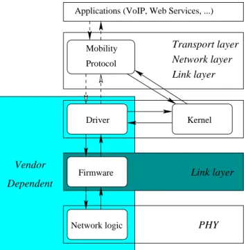
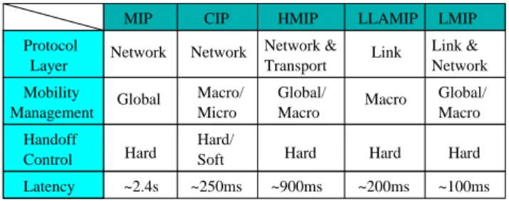
(2) 2. off was made in Section III which indicates that link-layer handoff was becoming the bottleneck to real time applications. Section IV introduces the proposed optimization scheme to reduce the latency of link-layer handoff procedure. The comparisons with IEEE 802.11 standard to evaluate performance enhancement are presented in Section V. In Section VI the compatibility of the proposed scheme and the phase of handoff execution are discussed. Finally, Section VII evaluates the research and the conclusions are presented.. MIP. CIP. HMIP. LLAMIP. LMIP. Network. Network. Network & Transport. Link. Link & Network. Mobility Management. Global. Macro/ Micro. Global/ Macro. Macro. Global/ Macro. Handoff Control. Hard. Hard/ Soft. Hard. Hard. Hard. Latency. ~2.4s. ~250ms. ~900ms. ~200ms. ~100ms. Protocol Layer. Table 1. Comparison of different Mobility Protocols.. II. MOBILITY PROTOCOL In the last few years, several Mobility Protocols have been proposed to support mobility-enabling nature of wireless LANs. It can be broadly classified into three categories: Micromobility (intrasubnet mobility), Macromobility (intradomain mobility) and Global mobility (interdomain mobility) due to its administrative domain [12]. In general, the primary goal of Mobility Protocol is to ensure continuous and seamless connectivity between micromobility and macromobility, which occur over short timescales. Global mobility involves longer timescales, where the goal is to ensure that MNs can reestablish communication after a move rather than provide continuous connectivity. In a cellular environment there are two kinds of handoff: intracell and intercell. Intracell handoff occurs when a user, moving within a cell, changes radio channels to minimize interchannel interface under the same network. On the other hand, intercell handoff occurs when an MN moves into an adjacent cell. Intercell handoff may be performed in two ways: soft and hard. If two networks simultaneously handle the interchange between them while performing the handoff, it is a soft handoff. Soft handoff is achieved by proactively notifying the new network before actual handoff. Thus, it minimizes packet loss, but delay incurred may be more. In hard handoff, one network takes over from another in a relay mode, so delay as well as signaling is minimized, but it does not guarantee zero packet loss. In infrastructure mode wireless LANs, the handoff is hard since a MN can communicate with exactly one AP before and after a handoff. And it is forward since the MN cannot communicate with the old MA during the handoff and has to carry out the handoff by reestablishing a connection with the new MA in the new network. These limits make many proposed Mobility Protocols cannot be implemented correctly or achieve the performance it expects in the actual network environment. The earliest Mobility Protocol is Mobile IP (MIP) [10]. It provides IP level mobility to allow MNs to roam across wireless LANs without loss of network-layer connectivity and disrupting transport sessions. In MIP, there are home agents (HAs) and foreign agents (FAs) running on the wired network. These MAs periodically broadcast MIP advertisements on the wireless LANs. Whenever a MN migrates from one subnet to another, it will receive MIP advertisements from the corresponding FA. The MN intercepts these advertisements and sends a registration request to the newly discovered FA. There is an IP-over-IP tunnel between FA and HA be established after due authentication. Finally, the MN sent a Binding Update message to its HA. From this point onwards, the data transferred between MN and servers can through the bidirectional tunnel. If the MN migrates. to a new foreign subnet, it needs to bind with the FA of the new foreign subnet, and needs to dismantle the association with the FA in the previous subnet. This procedure is performed every time the MN enters a new wireless IP subnet. The entire process of switching from one MA to another as a MN moves across adjacent wireless IP subnets is called MIP handoff. Most of the following Mobility Protocols are referring to MIP. Some of these improving protocols are described as follows. Cellular IP (CIP) [15] is a technique to use proprietary control messages for location management. The messages will be routed in a regional area therefore speeding up the registrations and reducing the handoff delay. Hierarchical MIP (HMIP) [3] is an extension of MIP, it employs a hierarchy of FAs to locally handle MIP registrations. Registration messages establish tunnels between neighboring FAs along the path from the MN to a gateway FA. The method proposed by Yokota et. al. [16] named LLAMIP is use an AP and a dedicated MAC bridge to reduce packet transmission interruptions in both the forward and reverse directions. Another improvement proposed by Sharma et. al. [13] named LMIP use some information from network card driver to speed up the movement detection. It also designed a MIP advertisement caching and relay proxy to reduce the handoff time. Table 1 makes a brief comparison of these different Mobility Protocols. From Fig. 1, it presents that Mobility Protocol is transparent to applications. Although some Mobility Protocols can reduce handoff by took advantage from driver directly, most of them must be triggered by the information provided from system kernel. No matter which layer the Mobility Protocol operated, it cannot break away from the influence of firmware since the firmware controls the link-layer handoff in the lower-layer. Thus, if there is a scheme can reduce the latency of link-layer handoff, all Mobility Protocols should get advantage from it. Next section will describe the influence of link-layer handoff in detail.. III. LINK-LAYER HANDOFF To analyze the link-layer handoff procedure, it is split into three sequential phase: potential, probe and auth. The goal of the potential phase is the detection of the need for the handoff. Following, the probe phase collects the acquisition of the information necessary for the handoff. Finally, the handoff is performed during the auth phase..
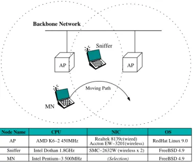
(3) 3. potential Orinoco 802.11b Silver Backbone Network. AP. 11 00. Total. 1021. 71. 1. 1093. 1702. 273. 2. 1977. ZoomAir 4100. 894. 265. 2. 1161. Symbol LA−2400. 1267. 102. 3. 1372 (ms). D−Link DWL−520 Sniffer. probe auth. AP. Table 2. The duration of link-layer handoff for selected cards. Moving Path. AMD K6−2 450MHz. Sniffer MN. Intel Dothan 1.8GHz Intel Pentium−3 500MHz. NIC Realtek 8139c(wired) Accton EW−3201(wireless) SMC−2632W (wireless x 2) (Selection). OS. Beacon. Old AP. Weak Signal. RedHat Linux 9.0 FreeBSD 4.9 FreeBSD 4.9. .... A. Experiment In this subsection, the duration of each handoff phase was measured in an experimental network environment as shown in Fig. 2. The wired LAN portion was constructed with 100BaseT and the wireless LAN portion was constructed with 802.11b. The version 0.3.9 of Host AP driver [4] was used in each AP to make them have AP functions and set their channel as 1 and 6 respectively. Host AP driver also installed on Sniffer to make it has a monitor mode which enables a designed program to read raw IEEE 802.11 frames on one particular channel. Thus by capturing traffic from two WNICs (on channel 1 and 6) on Sniffer, it is able to sniff all frames transmitted by participating entities in the common RF medium. The open system was used to be the default authentication algorithm. During the experiment, the only traffic in the network was a flow of packets generated by the MN which was transmitting 64 bytes of UDP packets at 100 ms intervals. Four commercial IEEE 802.11b WNICs with different chipsets were selected to measure their handoff time as average of 30 repetitions. From the experiments, it is noted that all commercial WNICs take advantage of the information provided by the physical layer and completely skip the potential phase. These cards start the probe phase when the strength of the received radio signal degrades below a certain threshold. Since the handoff measurements using physical layer information have already been reported by Mishra et. al. [8], this paper prefer to provide readers an advanced and a detailed measurement (i.e., without support from the physical layer). The handoff was forced by abruptly switching off the radio transmitter of the AP to which the MN was connected. This allows assessing the importance of using the signal strength in deciding to start the handoff. Thus, the handoff time in the experiments was measured from the first non-acknowledged data frame until the transmission of the first frame via the new AP. The measuring results are presented in Table 2. All APs within range on all channels. Fig. 2. Experiment network.. Failed Frame Transmission. Probe Request Probe Response Probe Request. .... Link−Layer Handoff. CPU. AP. MN. potential phase. Node Name. New AP. probe phase. 11 00. Authentication Authentication Reassociation Request. auth phase. MN. Reassociation Response. Mobility Protocol Fig. 3. The link-layer handoff procedure.. B. Analysis The Fig. 3 illustrates the common case of link-layer handoff procedure. The analyses of experiment are divided into three parts depending on the definition of handoff phase and detailed below. B.1 potential phase The handoff can be classified into two categories due to which one initiated the handoff. The actions during the potential phase vary depending on which entity initiated the handoff. When the.
(4) 4. handoff is initiated by network, the potential phase consists of a single disassociation message sent by an AP to the MN. However, the most common handoff is the one initiated by the MN due to its mobility-enabling nature, in which MNs have to detect the lack of radio connectivity based on weak received signal reported by the physical layer or failed frame transmissions. The observed results were quite startling - none of the analyzed cards used the lack of beacon reception to discover that the AP was not in range. All cards decide the need for the handoff by failed frame transmissions. From Table 2, it shows the duration of potential phase is the longest in all cases and widely varies among different cards. This was expected since the IEEE 802.11 standard only specifies the mechanisms to implement the handoff, but their combination and duration are left unspecified. The purpose was to allow the manufacturers some freedom to balance between different tradeoffs such as fast reaction or low power consumption. The main factor in controlling the duration of potential phase is the number of allowed failed frames. It varies with each card because when a frame is not acknowledged, the MN can not differentiate whether the reason was a collision, congestion in the cell or the AP being out of range. Different cards use different assumptions depending on their purpose. For instance, the D-Link DWL-520 is designed for a desktop PC, thus it assumes that the AP is always in range and retransmits for a longer period than the ZoomAir 4100 designed for laptops.. new AP first. Authentication consists of two or four consecutive frames depending on the authentication method used by the AP. Since the open system used in the experiment, there are only two authentication frames exchanged between the MN and the AP. Following, the MN sends a reassociation request to the new AP to associate with the new AP. After AP confirms the reassociation, it will send a reassociation response to the MN. Upon successful auth phase, the handoff is completed and the Mobility Protocol can take over the following handoff progress. B.4 Conclusions of experiment From the experiments, the following conclusions can be drawn. First, the potential phase is the primary contributor to the overall link-layer handoff latency. Fortunately, all cards can take advantage of the information provided by the physical layer to skip it completely. Second, different cards presented different performance, but none matched the delay requirements of real time applications during handoff (e.g., the guidelines for jitter in VoIP applications is recommended the overall latency not to exceed 50 ms [7]) even though the potential phase can be ignored. The probe phase becomes the bottleneck in link-layer handoff process. An optimization scheme is needed to reduce the latency of link-layer handoff within acceptable bounds. Then, the whole handoff latency (i.e., includes link-layer and Mobility Protocol) can have a chance to reach the requirements of real time applications.. B.2 probe phase The probe phase consists of serial actions performed by the MN to find the APs in range. Since the IEEE 802.11 standard specifics that APs can operate in any channel of the allowed set, all allowed channels must be searched in probe phase. There are two methods to search a channel, active and passive searching. In passive searching, MNs listen to each channel for the beacon frames from APs. The main problem of this method is how to calculate the time to listen to each channel. This time must be longer than the beacon period, but the beacon period is unknown to the MN until the first two beacons are received. Another problem is its performance. Since the whole set of allowed channels must be searched, MNs need over a second to discover the APs in range with the default 100 ms beacon interval. There are 11 and 13 allowed channels in USA and most of Europe respectively, thus it would take 1.1 and 1.3 seconds in probe phase when MNs perform passive searching. If the faster searching is needed, MNs must perform active searching. From analyzing captured frames, all cards performed active searching. It means that MNs will broadcast a probe request frame on each allowed channel and wait for the corresponding probe response generated by the AP. The variance of duration in experiment is due to the different number of probe requests sent per channel and more significantly due to the time to wait for probe responses. The reason to make this is the same as the one in potential phase - The IEEE 802.11 standard left the combination and duration of the mechanisms unspecified. B.3 auth phase The auth phase is the execution of the handoff. To perform the handoff, the MN must exchange authentication frames with the. IV. LINK-LAYER OPTIMIZATION SCHEME A. Preliminary IEEE 802.11-based wireless LANs which consist of APs and WNICs have been set in many places. It may be impractical to make any incompatible modifications with existing devices as the result of doing this may mean an extensive change in the backbone of the networks. The proposed scheme can be achieved through firmware upgrade, no extra cost is needed. Since the potential phase can be skipped completely via taking advantage of the information provided by the physical layer and the latency in auth phase is not significant, the probe phase becomes the main contributor to the overall link-layer handoff latency. A designed field is used to optimize the interactions between AP and WNIC. With the optimized parameters, whole link-layer handoff latency can be reduced to an acceptable level. B. Link-Layer Optimization Scheme B.1 Optimizing operations To optimize the operations of link-layer handoff, the proposed scheme focuses on probe phase and designs a novel field. This field has been appended to the beacon which AP broadcasts usually to avoid all channels being searched in probe phase. The details of this field are presented in Fig. 4. The Order of this field in beacon is set to 11 which is unused in the IEEE 802.11 standard. The Element ID is 65 and the Length is 4. The Status is used to represent the channel usage status. B0 to B12 are used to represent the status of channel 1 to 13 respectively, and B13 to B15 are reserved. If AP uses channel.
(5) 5. Order:11. B 15. Element ID. B0. Length. Status. 1. 2. Moving path. Stage. Channel_Register changing B 15. Octets:. 1. Element ID Length. 65 (reserved in standard) 4. I MN. Status B 0 ~ B 12 Channel 1~13. B 13 ~ B 15. Reserved. II. 11 00 MN. Fig. 4. The designed field appended to beacon.. n to make communications, it will set Bn−1 to 1 and keep other subfields to 0. On AP, there is a message exchange mechanism must be implemented to overcome the physical limitation of signal receiving when different channels are used on AP and MN. The Status subfield should include the channel usage status of neighboring APs. This can be done by a centralize server that periodically exchanges channel usage status with all APs in a regional network (e.g., in a building). Since the position of AP usually is fixed, the interval of this message exchange can be set to large (e.g., 5 minutes). In addition, the size of exchange message is very small. Therefore, no observable traffic load will appear in the network. On WNIC, there is a 2-bytes register - Channel_Register used to collect the received channel usage status of APs in range. The register upgrade can be completed in a very short time since the WNIC can take the received Status subfield to make a simple logic instruction "OR" with Channel_Register to renew, no significant load generated. In probe phase, the WNIC can depend on the records of Channel_Register to send probe request to specific channels. After link-layer handoff completed, the WNIC will reset its Channel_Register to avoid the influences from expired information. For the compatibility reason, a special case must be considered. If all subfields in the Channel_Register are 0 or there are no responses from the recorded channels, the WNIC should send the probe request following the IEEE 802.11 standard. Since it may mean there is no AP supports the proposed scheme in range. The previously discussed scheme is demonstrated in Fig. 5. AP1 and AP2 use channel 6 and 11. After channel usage status exchanged, they will set B5 and B10 to 1 in their broadcasting beacon respectively. The detailed actions are described below: (i) After MN enters the transmission range of AP1 , it can receive periodically broadcasting beacon from AP1 . Then, the WNIC can fetch the field Order 11 from received beacon and update its Channel_Register with Status subfield. After update, the Channel_Register will the same as the case in Stage II. (ii) When MN detects the lack of radio connectivity of AP1 (from Stage III moves to Stage IV), probe phase has been triggered. The WNIC can depend on the records of Channel_Register to only send the probe request to channel 6 and 11. This can eliminate the unnecessary channel searching operations in probe phase. (iii) After link-layer handoff completed, MN has associated. B0. 0 0 0 0 0 0 0 0 0 0 0 0 0 0 0 0. 11 00 00 11. B 15. Channel 6. B0. 0 0 0 0 0 1 0 0 0 0 1 0 0 0 0 0. AP 1. III. MN. B 15. 11 00. B0. 0 0 0 0 0 1 0 0 0 0 1 0 0 0 0 0. Channel 11 AP 2. IV MN. 11 00 00 11. B 15. B0. 0 0 0 0 0 1 0 0 0 0 1 0 0 0 0 0. Fig. 5. Link-layer handoff with the proposed optimization scheme.. with AP2 and reset its Channel_Register. Subsequently, MN receives the beacon from AP2 and sets its Channel_Register as the case in Stage IV. B.2 Tuning parameters Besides optimizing operations, there are two parameters (MinChannelTime and MaxChannelTime) must be tuned to speed up the probe phase. Since after MN broadcasts probe request to specific channels, it still needs to wait for the probe response generated by the AP. The time to wait for responses depends on the channel activity after the probe request sent. If the channel is idle during MinChannelTime (i.e., there is neither response nor any kind of traffic in the channel), the searching is finished and the channel is declared idle. If there is any traffic during this time, the MN must wait MaxChannelTime. Note that searching MNs might not be able to sense other MNs communicating with the AP, but they will always receive the acknowledgement sent from the AP and thus they will wait MaxChannelTime for probe responses. The IEEE 802.11 standard does not define the values of MinChannelTime and MaxChannelTime even they control the duration of the channel searching. Both parameters are measured in Time Units (TUs) and the IEEE 802.11 standard defines a TU to be 1024 µs. To minimize them, the proposed scheme finds out the reasonable values for them. First, MinChannelTime which is the maximum time an AP would need to answer given that the AP and channel are idle is calculated. If the probe response generation time and the propagation time are ignored, the IEEE 802.11 medium access function establishes that the maximum response time is given by the following equation. MinChannelTime = DIFS + (aSlotTime × aCWmin) In this equation, DIFS is the Distributed InterFrame Space, aSlotTime is the length of a slot, and aCWmin is the maximum.
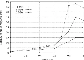
(6) 6. C. Optimized Results When a channel is searched, a probe request is broadcasted and then the MN waits for the probe response. Since the probe request is sent to the broadcast address, there is no acknowledgement responded. Therefore, at least two consecutive probe requests must be sent to reduce the influence of possible collision. Each probe request must follow the same channel access procedure as the data packets, thus they will experience the transmission delay. Let Td be the transmission delay, Tb be the time needed to search a busy channel (i.e., with traffic) and Ti be the time to search an idle channel. Then, Tb and Ti can be calculated as follows. Tb = 2Td + MaxChannelTime Ti = 2Td + MinChannelTime Each channel searching operation spent Tb or Ti . Let n be the number of nonzero subfields in Channel_Register, and o be the number of APs which are already out of range. With the proposed optimization scheme is used, the WNIC does not need to search all channels in probe phase. The optimized duration of probe phase Tp could be concluded by the following equation. Tp = (n-o)Tb + oTi. V. SIMULATION AND ANALYSIS Since the proposed optimization scheme must modify the firmware of WNIC and AP to achieve, no real devices experiments could be made without vendors’ support. Simulations are performed by ns-2 2.28 [14] with some necessary modifications (e.g., beacon transmission and designed field processing were added to IEEE 802.11 module). In this section the simulations of the proposed optimization scheme are presented and compared with the IEEE 802.11 standard. The wireless link speed. 50 45 Latency of probe response (ms). number of slots in the minimum contention window. These values are defined in the IEEE 802.11 standard. After inserting them in the equation, the value 670 µs can be obtained. Since MinChannelTime must be expressed in TU, its value could be concluded to be 1 TU. The definition of MaxChannelTime is more complicated. Since MaxChannelTime is the maximum time to wait for a probe response when the channel is busy, it should be large enough as to allow the AP to compete for the medium and send the probe response. This time is a variable since it depends on the cell load and number of MNs competing for the channel. In order to find a reasonable value for MaxChannelTime, a simulation was ran to measure the time to transmit the probe response. The simulation results are presented in Fig. 6. The results confirm that the transmission time of a probe response depends on the traffic load and the number of MNs. In addition, they also show that MaxChannelTime is not bounded as long as the number of MNs can increase. A value for MaxChannelTime that would prevent overloaded AP to answer in time is suggested. Since 10 MNs per cell seems to be an appropriate number to achieve a good cell throughput [1], Fig. 6 indicates that 10 TUs would be a reasonable choice for MaxChannelTime.. 1 MN 5 MNs 10 MNs. 40 35 30 25 20 15 10 5 0 0. 0.2. 0.4 0.6 Traffic load. 0.8. 1. Fig. 6. Latency of probe response.. is based on IEEE 802.11b. The effect on radio interference of closed channels in the IEEE 802.11 standard is more obvious than in the proposed optimization scheme. This is because the proposed scheme can prevent unnecessary probe requests being sent, so the possibility of collision could be reduced. Therefore, for the reason that the results can be compared clearly, the effect on radio interference of closed channels is ignored in this simulation. A. Latency of Probe Response The purpose of this experiment is to find out a reasonable value for MaxChannelTime, the number of MNs 1, 5, and 10 are simulated. Fig. 6 illustrates the results. The probe response time shown is the average of 30 transmissions for each load level with channel bit rate set to 2Mbps, the maximum possible rate for the probe response in IEEE 802.11b. In the most situations, the probe response can be responded in 10 ms. After analyzed, the proposed optimization scheme defines MaxChannelTime as 10 TUs. B. Duration of probe phase In this experiment, the improvements of the proposed optimization scheme can be observed clearly in Fig. 7. The IEEE 802.11 standard is compared with the proposed scheme when there are 5 and 10 MNs in the WLAN. After tuning parameters, MinChannelTime and MaxChannelTime used in the proposed scheme are 1 TU and 10TUs respectively. But these parameters are not specified in the IEEE 802.11 standard. By analyzing the transmission logs generated from the experiments in Section III, the parameters of Orinoco 802.11b Silver are 3 TUs and 30 TUs for MinChannelTime and MaxChannelTime, respectively. This experiment takes these two parameters of Orinoco card as the parameters in the IEEE 802.11 standard and sets the traffic load to 50%. From Fig. 7, the curves after the number of MNs in the WLAN reached are very stable. It is because MNs have more chances to distribute to the different channels, the possibility of idle channel be distinguished becomes higher when channel searching. But it will different in the actual network environ-.
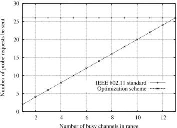
(7) 7. 30. 5 MNs Number of probe requests be sent. 180 Duration of probe phase (ms). 160 140 120 IEEE 802.11 standard Optimization scheme. 100 80 60 40. 25 20 15 10 IEEE 802.11 standard Optimization scheme. 5. 20 0. 0 2. 4 6 8 10 Number of available channels in range. 12. 10 MNs. 2. 4 6 8 10 Number of busy channels in range. 12. Fig. 8. Number of probe requests be sent.. Duration of probe phase (ms). 350 300. channels must be searched in the IEEE 802.11 standard, no matter how many busy channels in range the results are the same. The proposed scheme, however, can depend on the records of Channel_Register to do a smart search, so the results are increasing with the busy channels in range. In a WLAN with three independent channels, it is 77% less than the one in the IEEE 802.11 standard during probe phase.. 250 200 IEEE 802.11 standard Optimization scheme. 150 100 50. VI. DISCUSSION. 0 2. 4 6 8 10 Number of available channels in range. 12. Fig. 7. Duration of probe phase.. ment. The differences between the proposed scheme and IEEE 802.11 standard will become larger. Since the closed channels will interfere in radio signal transmission of each other. In the IEEE 802.11 standard, a channel searching operation must spend MaxChannelTime even the searching channel is idle if there are any signal transmission during MinChannelTime in the closed channel. This situation can be eased since not all channels must be searched in the proposed scheme. In an arranged WLAN, there are usually three independent channels which should not interfere with each other be set (e.g., channel 1, 6 and 11). By observed the simulation results, the proposed scheme could reduce the duration of probe phase to only 33 ms which is only 24.1% of the one in the IEEE 802.11 standard even there are 10MNs in the high traffic load WLAN. This makes whole handoff latency has a chance to meet the high requirements of real time applications. The design goal of the proposed scheme is accomplished. C. Power consumption The power consumption is a key issue in the wireless research area. The less packets transmitted, the more power saved and lower possibility of collision got. The number of probe requests are sent during probe phase when the proposed scheme and IEEE 802.11 standard are used is shown in Fig. 8. Since all. A. Compatibility When a novel scheme presented, the compatibility is another important thing besides its contributor. The proposed optimization scheme endeavors to reduce the latency of linklayer handoff and make compatible with existing devices. It can be achieved through firmware upgrade which supported by the most of commercial products. The signaling to perform the linklayer handoff is specified in the Medium Access Control protocol of the IEEE 802.11 standard and is common to the IEEE 802.11a/b/g supplements. Therefore, the proposed optimization scheme can apply to all of them in general. In AP, a designed field is appended to the broadcasting beacons. This 4-bytes attachment will not cause the beacon be fragmented. AP only needs to depend on its channel usage status to set the corresponding subfield before encapsulation of beacon. The main problem is on WNIC, since it needs an extra register as Channel_Register. Fortunately, most of devices reserved some free registers when leave the factory. Take ADM8262 which is a controller of WLAN Base Band Processor/Medium Access Control (BBP/MAC) as an example [6]. There are two 4-bytes registers RR_CSR13A and TOFS_CSR17 reserved in its data sheet. Each of them can be used to as the Channel_Register in the proposed scheme. B. Reduction of auth phase From the experiments in the Section III, auth phase is the shortest phase in the whole link-layer handoff procedure. The measurements show that the auth phase using open system authentication is 3 ms at most for an empty cell, thus reducing the.
(8) 8. auth phase will not obviously reduce the overall link-layer handoff time. Furthermore, there are more complicated authentication schemes which are not the researching ambit in this paper that require querying an external agent. In these cases, the authentication must be completed before the handoff execution [9] to reduce the handoff latency. VII. CONCLUSIONS In this paper, an optimization scheme which can reduce the latency of link-layer handoff has been presented. To analysis the details of link-layer handoff procedure, a real environment experiment is made. It concludes that the requirements of real time applications are not meet and points out where the bottleneck is. The proposed optimization scheme endeavors to reduce link-layer handoff latency and make it more acceptable. A novel designed field is appending to the beacon AP broadcasts usually and wireless interface card can depends on the records of its special register to search specified channels. Two important parameters during probe phase are also being tuned. These modifications can be achieved through firmware upgrade in the existing devices, and no compatibility problems occurred. By using the proposed scheme, no matter which Mobility Protocol is used in the upper-layer, it can be triggered early and the duration of handoff procedure can be reduced. REFERENCES [1] [2] [3] [4] [5] [6] [7] [8] [9] [10] [11] [12] [13] [14] [15] [16]. G. Bianchi, “Performance analysis of the IEEE 802.11 distributed coordination function,” IEEE Journal on Selected Areas in Communication, Vol. 18, No. 3, pp. 535-547, March 2000. R. Caceres and V. N. Padmanabhan, “Fast and Scalable Wireless Handoffs in Support of Mobile Internet Audio,” Mobile Networks and Applications, pp. 180-188, December 1998. E. Gustafasson, A. Jonsson and C. Perkins, “Mobile IP regional registration,” Internet draft, draft-ietf-mobileip-reg-tunnel-09.txt, June 2004. “Host AP driver,” http://hostap.epitest.fi IEEE, “Part11: Wireless LAN Medium Access Control (MAC) and Physical Layer (PHY) Specifications,” IEEE Standard 802.11, 1999. Infineon technology, “ADM8262 PCI/Cardbus/Mini-PCI WLAN MAC/BBP Controller Preliminary Data Sheet, Rev. 1.1,” Mar. 2005. International Telecommunication Union, “General Characteristics of International Telephone Connections and International Telephone Circuits,” ITU-TG. 114, 1988. A. Mishra, M. Shin and W. Arbaugh, “An Empirical Analysis of the IEEE 802.11 MAC Layer Handoff Process,” ACM SIGCOMM Computer Communication Review, Vol. 33, Issue 2, April 2003. S. Pack and Y. Choi, “Pre-authenticated fast handoff in a public wireless LAN based on IEEE 802.1x Model,” IFIP TC6 Personal Wireless Communications 2002, October 2002. C. Perkins, “IP Mobility Support for IPv4,” RFC3344, IETF, August 2002. J. Rosenberg et.al., “SIP: Session Initiation Protocol,” RFC 3261, IETF, June 2002. D. Saha, A. Mukherjee and M. Chakraborty, “Mobility Support in IP: A Survey of Related Protocols,” IEEE Network, pp. 34-40, November/December 2004. S. Sharma, N. Zhu and T. Chiueh, “Low-Latency Mobile IP for Infrastructure-Mode Wireless LANs,” IEEE Journal on Selected Areas in Communication, Vol. 22, No. 4, pp.643-652, May 2004. “The Network Simulator - ns-2,” http://www.isi.edu/nsnam/ns/ A. G. Valkó, “Cellular IP: A New Approach to Internet Host Mobility,” ACM SIGCOMM Computer and Communication Review, Vol. 29, No. 1, pp. 50-65, January 1999. H. Yokota, A. Idoue, T. Hasegawa and T. Kato, “Link Layer Assisted Mobile IP Fast Handoff Method over Wireless LAN Networks,” in MOBICOM’02..
(9)
數據
+3
相關文件
NETs can contribute to the continuing discussion in Hong Kong about the teaching and learning of English by joining local teachers in inter-school staff development initiatives..
massive gravity to Ho ř ava-Lifshitz Stochastic quantization and the discrete quantization scheme used for dimer model and crystal melting. are
5 Economic Benefits of the Independent Visitor Scheme for Hong Kong:How Large are
Schools participating in the Pilot Scheme on Promoting Interflows between Sister Schools in Hong Kong and the Mainland (the “Pilot Scheme”) have been organising various
While Scheme-KGs may have flexibility in maintaining the current arrangements in learning and teaching activities 1 , they are required to appoint teachers to meet the
Microphone and 600 ohm line conduits shall be mechanically and electrically connected to receptacle boxes and electrically grounded to the audio system ground point.. Lines in
Since the sink is aware of the location of the interested area, simple greedy geographic routing scheme is used to send a data request (in the form of
The schematic diagram of the Cassegrain optics is shown in Fig. The Cassegrain optics consists of a primary and a secondary mirror, which avoids the generation of
