VLSI Implementation of Memory-Efficiency Multiplierless DCT and IDCT Processors
6
0
0
全文
(2) One may take the iteration sequence: {0, 0, 0, 1, 2, …., n } for the CORDIC algorithm in the circular coordinate system to expand the convergence range of angles as follows. n. θ max = arctan( 2 − n ) + 2 ⋅ arctan( 2 0 ) + ∑ arctan 2 − j j =0. (6). ≅ 3 .3141 (189 o ) > 180 o Thus, the convergence range of angles is expanded to ± 180◦, and the input angle can be unlimited [26]-[27].. 3: THE CORDIC-BASED DCT AND IDCT ALGORITHM The N-point 1-D DCT is defined as 1 N −1 ⎡ ( 2 n + 1) m π ⎤ (7) Y (m) = ∑ 2 K m cos ⎢ ⎥ ⋅ x(n) 2N ⎣ ⎦ N n =0 1 where m = 0,...., N − 1, K m = for m = 0 , and 2 K m = 1 for m > 0 . For image applications, a separable 2-D DCT can be obtained by using the tensor product of two 1-D DCTs. Specifically, the M × N -point 2-D DCT is defined as 2 ⋅ c (u ) c ( v ) Z (u , v ) = ⋅ M ⋅N (8) M −1 N −1 ⎡ ( 2m + 1)uπ ⎤ ⎡ ( 2n + 1)vπ ⎤ ∑ ∑ x ( m, n) ⋅ cos ⎢ ⎥ ⋅ cos ⎢ ⎥ 2M 2N m =0 n =0 ⎣ ⎦ ⎣ ⎦ 1 where u = 0,...., M − 1, v = 0,...., N − 1 , c(k ) = for 2 k = 0 , and c(k ) = 1 for k > 0 . Equation (8) can be rewritten by. Z (u, v) =. ⎡ (2m + 1)uπ ⎤ ∑ 2c(u) ⋅ cos⎢ ⎥⋅ ⎣ 2M ⎦ M m=0. 1. M −1. ⎫ ⎧ 1 N −1 ⎡ (2n + 1)vπ ⎤ ⋅ x(m, n)⎬ ∑ 2c(v) ⋅ cos⎢ ⎨ ⎥ ⎣ 2N ⎦ ⎭ ⎩ N n=0. (9). For 8× 8 DCT, let ⎡1 ⎢a ⎢ ⎢b ⎢ 1 ⎢c T = ⋅ 8 ⎢1 ⎢ ⎢d ⎢e ⎢ ⎣⎢ f. 1. 1. 1. 1. 1. 1. c. d. f. − f. −d. −c. e. −e. −b. −b. −e. e. − f −1. −a −1. −d 1. d 1. a −1. f −1. −a. f. c. −c. − f. a. −b. b. −e. −e. b. −b. −d. c. −a. a. −c. d. 1 ⎤ − a ⎥⎥ b ⎥ ⎥ −c⎥ 1 ⎥ ⎥ −d⎥ e ⎥ ⎥ − f ⎦⎥. (10). a=. Z = TY t. (11). where Y = TX t . As a result, the separable 2-D DCT computation can be obtained by using 1-D DCT computations as follows. 2-D DCT(X) = 1-D DCT((1-D DCT(X))t. (12). Similarly, a separable M × N -point 2-D IDCT can be obtained, which is given by 2 ⋅ c (u ) c ( v ) ⋅ x ( m, n ) = M ⋅N (13) M −1N −1 ⎡ ( 2m + 1)uπ ⎤ ⎡ ( 2n + 1)vπ ⎤ ⋅ cos ∑ ∑ Z (u , v ) ⋅ cos ⎢ ⎥ ⎢ ⎥ 2M 2N u =0 v =0 ⎣ ⎦ ⎣ ⎦ 1 where µ = 0,...., M − 1,ν = 0,...., N − 1 , c(k ) = 2 for k=0, and c(k ) = 1 for k>0. Thus, the 2-D IDCT computation using 1-D IDCT computations is as follows. 2-D IDCT(Z)=1-D IDCT((1-D IDCT(Z))t ) (14) t t t In which, X=T ZT, Y = T Z , and therefore X= TtYt. (15). 3.1: FAST 1-D DCT ALGORITHM Equation (10) can be further decomposed to obtain a fast algorithm for 1-D DCT [28]. Specifically, 8-point fast DCT is as follows. 1 1 ⎤ ⎡ x (0) + x (7 ) ⎤ ⎡Y ( 0 ) ⎤ ⎡1 1 ⎢Y ( 2 ) ⎥ ⎢b e − e − b ⎥ ⎢ x (1) + x ( 6 ) ⎥ ⎥ ⎥⎢ ⎥=⎢ ⎢ (16) ⎢Y ( 4 ) ⎥ ⎢1 − 1 − 1 1 ⎥ ⎢ x ( 2 ) + x (5) ⎥ ⎥ ⎥⎢ ⎥ ⎢ ⎢ ⎣Y ( 6 ) ⎦ ⎣ e − b b − e ⎦ ⎣ x (3) + x ( 4 ) ⎦ ⎡ Y (1) ⎤ ⎡ a − c d − f ⎤ ⎡ x (0) − x (7 ) ⎤ ⎢Y (3) ⎥ ⎢ c f − a d ⎥⎥ ⎢⎢ − x (1) + x (6) ⎥⎥ ⎥=⎢ ⎢ (17) ⎢Y ( 5 ) ⎥ ⎢ d − c ⎥ ⎢ x ( 2 ) − x (5) ⎥ a f ⎥ ⎥⎢ ⎥ ⎢ ⎢ d c a ⎦ ⎣ − x (3) + x ( 4) ⎦ ⎣Y (7 ) ⎦ ⎣ f Based on equations (16) and (17), the data flow of 8-point DCT can be determined, which is shown in Figure 1. It is noted that CORDIC(2) and CORDIC(5) involved in Figure 1 have the same structure with rotation angle of. ⎛π ⎞ ⎛π ⎞ b = 2 cos ⎜ ⎟ , 2 cos ⎜ ⎟ , 16 ⎝ ⎠ ⎝8⎠ ⎛ 5π ⎞ ⎛ 3π ⎞ , , c = 2 cos ⎜ d = 2 cos ⎜ ⎟ ⎟ 16 ⎝ 16 ⎠ ⎝ ⎠ ⎛ 7π ⎞ ⎛ 3π ⎞ e = 2 cos⎜ ⎟ , and f = 2 cos ⎜ ⎟ .The transform ⎝ 16 ⎠ ⎝ 8 ⎠ coefficients Z (u , v ) of 8 × 8 DCT can be arranged. where. and grouped into an array denoted by Z, which can be written by. π. 16. ; CORDIC(3) and CORDIC(4). have the same structure with rotation angle of. 5π . 16. 3.2: FAST 1-D IDCT ALGORITHM By further decomposing equation (10), 8-point fast IDCT can be obtained, which is given by. - 118 -.
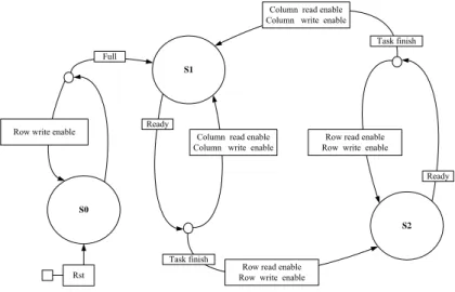
(3) ⎡ x(0)⎤ ⎡1 ⎢ ⎥ ⎢ ⎢ x(7)⎥ = ⎢1 ⎢ x(4)⎥ ⎢1 ⎢ ⎥ ⎢ ⎣ x(3) ⎦ ⎢⎣1. ⎡Y (0) + Y (4)⎤ ⎥ ⎢ Y (2) ⎥ f b e a c d ⎤⎢ ⎥ ⎢ Y (6) ⎥ b e − f − a − c − d⎥⎢ ⎥ (18) ⎢ Y (1) ⎥ ⎥ f c −d ⎢ −b −e a ⎥ Y (7) ⎥ ⎥ − b − e − a − f − a c ⎥⎦ ⎢ ⎢ Y (3) ⎥ ⎢ Y (5) ⎥ ⎦ ⎣. ⎡ x(1) ⎤ ⎡1 e − b c ⎢ x(5) ⎥ ⎢ ⎢ ⎥ = ⎢1 − e − b − d ⎢ x(2)⎥ ⎢1 − e b d ⎢ ⎥ ⎢ ⎣ x(6)⎦ ⎢⎣1 e − b − c. −d −c c d. −f a −a f. ⎡Y (0) − Y (4)⎤ ⎥ ⎢ Y (2) ⎥ − a ⎤⎢ ⎢ Y (6) ⎥ − f ⎥⎥ ⎢ ⎥ (19) Y (7 ) ⎥ f ⎥⎢ ⎥ ⎢ Y (1) ⎥ ⎥ a ⎥⎦ ⎢ ⎢ Y (3) ⎥ ⎢ Y (5) ⎥ ⎦ ⎣. Based on equations (18) and (19), the data flow of 8-point IDCT can be determined, which is shown in Figure 2. It is noted that the processor-R0 (with rotation π 5π and ) and the proceesor-R2 (with angles of 16 16 π 5π rotation angles of and ) have the same 16 16 6π . structure; and the processor-R1 rotates by angle of 16. 3.3: THE PROPOSED CORDIC-BASED 2-D DCT AND IDCT ARCHITECTURES Multiplication is the key operation for both DCT and IDCT. In the CORDIC-based processor with rotation mode in the circular coordinate system, multipliers of DCT and IDCT can be replaced by simple shifters and adders. Moreover, the arithmetic unit (AU) obtained by the use of double-rotation CORDIC algorithm has been taken into account to develop fast DCT and IDCT architectures. In comparison to the conventional CORDIC-based arithmetic unit, the proposed double-rotation CORDIC-based arithmetic unit can improve the latency more than 30% [29]. Thus, the hardware of arithmetic unit can be significantly saved and low-power consumption can be achieved. The overall relative error is less than 10 −3 provided that the length of registers is 16 bits, and the number of micro-iterations in the double-rotation CORDIC processor is set to 4 [27].. DCT/IDCT processors, two multiplexers and control unit are involved. Specifically, the 8-point 1-D DCT/IDCT input-processor, which is denoted by P1, writes the intermediate result into the row and column of SRAM bank alternately. The 8-point 1-D DCT/IDCT output-processor, which is denoted by P2, reads data from the column and raw of SRAM bank alternately and outputs the final result. The control unit manages the data flow and arranges the timing for 2-D operations. Figure 4 shows the finite state machine (FSM) of control unit.. 4.1: IMPLEMENTATION PROPOSED 1-D DCT PROCESSORS. Based on equations (11) and (15), an efficient parallel-pipelined architecture has been developed for both 2D DCT and IDCT. Figure 3 shows the proposed architecture for 8 × 8 DCT and IDCT processors. In which, one SRAM bank (64 words), two 8-point. THE IDCT. The implemented 8-point DCT/IDCT processor utilizes five CORDIC processors obtained by using the double-rotation CORDIC arithmetic [29]. Figure 5 and 6 show the proposed 8-point DCT processor and IDCT processor, respectively. As the transformation matrices involved in 1-D DCT and IDCT are column symmetry and row symmetry, respectively, the shuffle structures of DCT/IDCT processor are therefore simplified, and no multipliers are needed.. 4.2: IMPLEMENTATION PROPOSED 2-D DCT PROCESSORS. OF AND. THE IDCT. Figure 3 shows the proposed 2-D DCT/IDCT processor. In which, the latencies of the constituent 1-D DCT/IDCT processors are 64 clocks, hardware complexity is O(N- log 2 N ), and the throughputs are 8 outputs per cycle. As no multiplier is utilized in the proposed architecture, many desirable properties such as small area, low-power and high throughput are achieved. Table 1 shows the comparison of the proposed 2-D DCT/IDCT architecture to other commonly used architectures [9]-[13]. The proposed parallel-pipelined architectures for 2-D DCT and IDCT processors have been written in Verilog® and synthesized by TSMC 0.18 µm 1P6M CMOS cell libraries [30]. Their core sizes and power consumptions can be obtained from the reports of Synopsys® design analyzer and PrimPower® [31], respectively. The reported core sizes of 2-D DCT and and IDCT processor are 2372 × 2372 µ m 2 2396 × 2396 µ m 2. 4: THE PROPOSED 2-D DCT AND IDCT PROCESSORS. OF AND. ,respectively, and the power dissipations for 2-D DCT and IDCT processors are 127.7 mW at 1.8V with clock rate of 34.4MHz and 116.7 mW at 1.8V with clock rate 35.7MHz, respectively. Due to the limitation of paper size, the reports and layout view of the proposed 2-D IDWT processor are not presented here. Figure 7 and 8 show the layout views of the implemented 2-D DCT processor and IDCT processor, respectively. The proposed 2-D. - 119 -.
(4) DCT and IDCT processors are much suited to the applications of both JPEG and MPEG standards.. 5: CONCLUSION By taking into account the symmetry properties of the fast DCT/IDCT algorithm, high efficiency architectures with a parallel-pipelined structure have been proposed to implement DCT and IDCT processors. For image applications, a separable 2-D DCT/IDCT can be obtained by using the tensor product of two 1-D DCT/IDCT operations. Thus, the proposed 2-D DCT/IDCT processor is composed of two successive 1-D DCT/IDCT kernels. In the constituent 1-D DCT/IDCT processors, the double-rotation CORDIC algorithm with rotation mode in the circular coordinate system has been utilized for the arithmetic unit (AU) of both DCT and IDCT, i.e. the multiplication computation. The proposed DCT/IDCT architectures are not only regularly structured but also highly scalable and flexible as well. Thus, they are much suited to VLSI implementation with design trade-offs.. REFERENCES 1. Elliott, D. F., Kao K. R., “Fast Transforms Algorithms, Analysis, Applications,” Chapter 8, Walsh-Hadamard Transform, Prentice-Hall, (1982), 301-303. 2. Clarke, R. J., “Relation between the Karhenen Loeve and Cosine Transform,” IEEE Proceedings, Part F, Vol. 128, No. 6, (1981), 359-360. 3. Narasimha, M. J., Peterson, A. M., “On the Computation of the Discrete Cosine Transform,” IEEE Transactions on Communications, Vol. 26, No. 6, June 1978, pp. 934-936. 4. Haralick, R. M. “A Storage Way to Implement the Discrete Cosine Transform,” IEEE Transactions on Computers, (1976), 764-765. 5. Chen, W. H., Smith, C. H., Fralick, S. C., “Fast Computational Algorithm for the Discrete Cosine Transform,” IEEE Transactions on Communications, Vol. 25, No. 9, (1977), 1004-1009. 6. Sung, T. Y., “VLSI Parallel and Distributed Computation Algorithms for DCT Processors,” Proceedings IEEE International Phoenix Conference on Computer and Communications, Scottsdale, Arizona, USA, (1990), 121-125. 7. Sung, T. Y., “VLSI Parallel and Distributed Processing Algorithms for Multidimensional Discrete Cosine Transforms,” 1990 A Two-Track International Conference on Databases, Parallel Architectures, and their Applications, Miami Beach, Florida, USA, (1990), 36-39. 8. Sung, T. Y., “Novel Parallel VLSI Architectures for Discrete Cosine Transforms,” Proceedings IEEE International Conference on Acoustics, Speech and Signal Processing, Albuquerque, New Mexico, USA, (1990), 998-1001. 9. Lee, Y. P., Chen, T. H., Chen, L. G., Ku, C. W.,“ A Cost-Effective Architecture for 8×8 two-dimensional DCT/IDCT Using Direct Method,” IEEE Transactions on Circuits Systems for Video Technology, Vol. 7, No. 1, (1997), 459-467. 10. Chang, Y. T., Wang, C. L., “New Systolic Array Implementation of the 2-D Discrete Cosine Transform and. Its Inverse,” IEEE Transactions on Circuits Systems for Video Technology, Vol. 5, No. 1, (1995), 150-157. 11. Hsiao, S. F., Shiue, W. R., “A New Hardware-Efficient Algorithm and Architecture for Computation of 2-D DCTs on a Linear Array,” IEEE Transactions on Circuits and Systems for Video Technology, Vol. 11, (2001), 1149-1159. 12. Hsiao, S. F., Tseng, J. M., “New Matrix Formulation for Two-Dimensional DCT/IDCT Computation and its Distributed-Memory VLSI Implementation,” IEE Proc.-Vis. Image Signal Process, Vol. 149, No. 2, (2002), 97-107. 13. Hsiao, S. F. , Hu, Y. H., Juang, T. B., Lee, C. H., “Efficient VLSI Implementations of Fast Multiplierless Approximated DCT Using Parameterized Hardware Modules for Silicon Intellectual Property Design,” IEEE Trans. Circuits and Systems, Part-I: Regular Papers, Vol. 52, No. 8, (2005), 1568-1579. 14. Srinvasan, V., Liu, K. J. R., “VLSI Design of High-Speed Time-Recursive 2-D DCT/IDCT Processor for Video Applications,” IEEE Transactions on Circuits Systems for Video Technology, Vol. 6, No. 1, (1996), 87-96. 15. Kuroda, T., “A 0.9-V, 150-MHz, 10-mW, 4mm2, 2-D Discrete Cosine Transform Core Processor with Variable Threshold-Voltage(VT) Scheme,” IEEE Journal of Solid-States Circuits, Vol. 31, No. 11, (1996), 1770-1778. 16. Rambaldi, R., Uguzzoni, A., Guerrieri, R., “A 35 µ W 1.1 Processor for V Gate Array 8 × 8 IDCT Video-Telephony,” Proceedings IEEE International Conference on Acoustics, Speech and Signal Processing, (1998), 2993-2996. 17. Chen, T. H., “A Cost-Effective 8 × 8 2-D IDCT Core Processor with Folded Architecture,” IEEE Transactions on Consumer Electronics, Vol. 45, No.2, (1999), 333-339. 18. Sung, T. Y., Sung, Y. H., “A Novel Implementation of Cost-Effective Parallel- Pipelined 8×8 DCT Processor,” The Fourth IEEE Asia-Pacific Conference on Advanced System Integrated Circuits (AP-ASIC) 2004, Fukuoka, Japan, (2004), 200-203. 19. Hu, Y. H., Wu, Z., “An Efficient CORDIC Array Structure for the Implementation of Discrete Cosine Transform”, IEEE Transactions on Signal Processing, Vol. 43, No. 1, (1995), 331-.336. 20. Jeong, H., Kim, J, Cho, W. K., “Low-Power Multiplierless DCT Architecture Using Image Data Correlation,” IEEE Transactions on Consumer Electronics, Vol. 50, No. 1, (2004), 262-267. 21. Gong, D., He, Y, Gao, Z., “New Cost-Effective VLSI Implementation of a 2-D Discrete Cosine Transform and Its Inverse”, IEEE Transactions on Circuits and Systems for Video Technology, Vol. 14, No. 4, (2004), 405-415. 22. Dimitrov, V., Wahid, K., Jullien, G., “Multiplication-Free 8 × 8 2D DCT Architecture Using Algebraic Integer Encoding”, Electronics Letters, Vol. 40, No. 20, (2004). 23. Alam, M., Badawy, W., Jullien, G., “A New Time Distributed DCT Architecture for MPEG-4 Hardware Reference Model”, IEEE Transactions on Circuits and Systems for Video Technology, Vol. 15, No. 5, (2005), 726-730. 24. Volder, J. E., “The CORDIC Trigonometric Computing Technique,” IRE Transactions on Electronic Computers, Vol. EC-8, (1959), 330-334. 25. Walther, J. S., “A Unified Algorithm for Elementary Functions,” Spring Joint Computer Conference Proceedings, Vol.38, (1971), 379-385.. - 120 -.
(5) 26. Hu, X., Harber, R. G., Bass, S. C., “Expanding the range of the Convergence of the CORDIC Algorithm”, IEEE Transactions on Computers, Vol. 40, No. 1, (1991), 13-21. 27. Sung, T. Y., Sung, Y. H., “The Quantization Effects of CORDIC Arithmetic for Digital Signal Processing Applications”, The 21st Workshop on Combinatorial Mathematics and Computation Theory, Taiwan, (2004), 16-25. 28. Sung, T. Y., “A Memory-Efficient and High-Speed Split-Radix FFT/IFFT Processor Based on Pipelined CORDIC Rotations,” to appear in IEE Proceedings – Vision, Image and Signal Processing, (2006).. 29. Sung, T. Y., Chen, C. S., Shih, M. C., “The Double Rotation CORDIC Algorithm: New Results for VLSI Implementation of Fast Sine/Cosine Generation,” 2004 International Computer Symposium (ICS-2004), Taipei, Taiwan, (2004), 1285-1290. 30.“TSMC 0.18 µm CMOS Design Libraries and Technical Data, v.3.2,” Taiwan Semiconductor Manufacturing Company, Hsinchu, Taiwan, and National Chip Implementation Center (CIC), National Applied Research Labs., Hsinchu, Taiwan, R.O.C., (2006). 31. Synopsys FPGA Express, http://www. synopsys.com/ products.. Table 1 Comparison of the proposed architecture to other commonly used architectures Hsiao[12]. Hsiao[13]. This Work. -. 10. 14. 36. 64. -. -. -. -. -. -. -. -. 3. 5. Complex-multipliers. -. -. 3. 3. -. -. Delay elements (Words). 256. 114. -. 171. -. -. Memory(Words). ~384. ~200. ~370. -. -. 70. Lee[9]. Chang[10]. Hsiao[11]. Real-adders. 134. 88. Real-multipliers. 28. Rotators. 8x8 2-D DCT/IDCT. Hardware complexity (AUs) Throughput (outputs/cycle). 2. O(NlogN). O(N ). O(logN). O(logN). O(logN)). O(N-logN). 16. 8. 2. 2. 2. 8. Pipelinability. no. no. no. no. yes. yes. Parallelism. yes. yes. yes. yes. yes. yes. x (0 ). -1. x (2). -1. x (4). C O RD IC (1). x (7 ). -1. CO R D IC (2). Y(0). Y (4). Y(4). Y (6). Y(3). Y(5). Y (2). -1. x (6 ). Y (0). +1. Y (1). +1. -1. +1. +1. +1. +1. x(0). x(6). R0 R_u. +1. R_d. +1. Y(2). x(7) -1 -1. -1. +1. -1. +1. +1. -1. -1. -1. x(1). x(4). R1. x (5). -1. CO R D IC (3). x (3). -1. CO R D IC (4). x (1). -1. CO R D IC (5). +1. +1. Y(6). Y (7 ) Y (5). Y(7). R2 R_u. Y (3). Y(1). -1. Fig. 1. Data flow of 8-point 1-D DCT. R_d. Fig. 2. Data flow of 8-point 1-D IDCT. P1. P2 Data Bus R/W. Control Unit. SRAM. Address Bus Fig. 3. The proposed architecture for 2-D DCT/IDCT processor. (P1and P2: 1-D DCT/IDCT processor). - 121 -. x(5). x(3). x(2).
(6) Column read enable Column write enable Task finish Full S1. Ready. Row write enable. Column read enable Column write enable. Row read enable Row write enable Ready. S0 S2. Task finish. Row read enable Row write enable. Rst. Fig. 4. The finite state machine of control unit. Y. x. (ADD/SUB)S & SHUFFLES. R0 (ADD/SUB)S & SHUFFLES. CORDIC(2). CORDIC(3). CORDIC(4). R1. (ADD/SUB)S& SHUFFLES. R2. CORDIC(5). (ADD/SUB)S&SHUFFLES. ADD/SUB. CORDIC(1). ADD. ADD. SUB. ADD. (ADD/SUB)S& SHUFFLES. (ADD/SUB)S& SHUFFLES. Y(0) Y(4). Y(6) Y(2). Y(1). Y(7). Y(5). Y(3). x(2) x(3) x(5) x(4). x(1) x(7) x(6) x(0). Fig. 6. The proposed 8-point IDCT processor. Fig. 5. The proposed 8-point DCT processor. SRAM. SRAM. Fig.7. The layout view of the implemented 2-D DCT processor. Fig.8. The layout view of the implemented 2-D IDCT processor. - 122 -.
(7)
數據


相關文件
“For Mother Tongue Education to be successful we need to help CMI students learn English
Type case as pattern matching on values Type safe dynamic value (existential types).. How can we
• Yeast are usually applied in baked goods with presence of wheat (gluten), so that porous and rigid structure can be formed.. Raising Agents in
implementation of public safety for the buildings under comprehensive reviews on fire prevention and evacuation and compares with related literature to establish the check items
Singleton,”A methd for computing the fast Fourier Transform with auxiliary memory and limited high-speed storage”, IEEE Trans. Audio
Iwai , “A self-aligned emitter base NiSi electrode technology for advanced high-speed bipolar LSIs” , in IEEE Bipolar/BiCMOS Circuits and Technology Meeting , pp..
Huan Liu and Dan Orban, “Cloud MapReduce: a MapReduce Implementation on top of a Cloud Operating System,” IEEE/ACM International Symposium on Cluster, Cloud and
D.Wilcox, “A hidden Markov model framework for video segmentation using audio and image features,” in Proceedings of the 1998 IEEE Internation Conference on Acoustics, Speech,
