Development of panel loudspeaker system: Design, evaluation
and enhancement
Mingsian R. Baia)and Talung Huang
Department of Mechanical Engineering, National Chiao-Tung University, 1001 TaHsueh Road, Hsin-Chu 300, Taiwan, Republic of China
共Received 10 July 2000; accepted for publication 13 March 2001兲
Panel speakers are investigated in terms of structural vibration and acoustic radiation. A panel speaker primarily consists of a panel and an inertia exciter. Contrary to conventional speakers, flexural resonance is encouraged such that the panel vibrates as randomly as possible. Simulation tools are developed to facilitate system integration of panel speakers. In particular, electro-mechanical analogy, finite element analysis, and fast Fourier transform are employed to predict panel vibration and the acoustic radiation. Design procedures are also summarized. In order to compare the panel speakers with the conventional speakers, experimental investigations were undertaken to evaluate frequency response, directional response, sensitivity, efficiency, and harmonic distortion of both speakers. The results revealed that the panel speakers suffered from a problem of sensitivity and efficiency. To alleviate the problem, a woofer using electronic compensation based on H2model matching principle is utilized to supplement the bass response. As indicated in the result, significant improvement over the panel speaker alone was achieved by using the combined panel-woofer system. © 2001 Acoustical Society of America.
关DOI: 10.1121/1.1371544兴
PACS numbers: 43.38.Ja, 43.38.Ar 关SLE兴
I. INTRODUCTION
For decades, the design concept of conventional loud-speaker has been centered at the principle of rigid piston. The common practice is to make the diaphragm of the speaker as light and stiff as possible such that the loud-speaker behaves as a rigid piston. Furthermore, the surface is generally made conical to further increase rigidity as well as on-axis sensitivity at low frequency. Although the technol-ogy is well established, conventional loudspeakers suffer from a problem: the sound generated by conventional loud-speakers becomes increasingly directional for high frequen-cies. This ‘‘beaming’’ effect results in the drop of sound power at the high frequency region. Consequently an audio system generally requires crossover circuits and multi-way loudspeakers to cover the audible frequency range, which makes the entire system unnecessarily large.
Panel speakers are based on a philosophy contradicting conventional design共Azima, 1998兲. A panel loudspeaker pri-marily consists of a panel and an inertia exciter共Fig. 1兲. The exciter is essentially a voice-coil driver with the coil attached to the panel. The magnet serves as a proof mass to produce inertia force. In lieu of a rigid diaphragm as used in conven-tional loudspeakers, flexible panels are employed as the pri-mary sound radiators. Resonance of flexural motion is en-couraged such that the panel vibrates as randomly as possible. The sound field produced by this type of distributed mode loudspeaker共DML兲 is very diffuse at high frequency. As claimed by the supporters of panel speakers, DML pro-vide advantages over the conventional counterpart such as compactness, linear on-axis, attenuation, insensitivity to
room conditions, bi-polar radiation, good linearity, and so forth 共Azima, 1998兲. Of particular interest is that the DML has a less pronounced beaming problem at high frequencies than conventional loudspeakers, which bypass the need for crossover circuits and multi-way high frequency speakers. DML began to find applications in multimedia, notebook computers, mobile phones, high-fidelity audio systems, pub-lic addressing systems, projection screens, pictures, and decorations共Azima, 1998兲.
Although commercial panel speakers may have been around for more than a decade, only recently has this concept been subjected to scientific analysis devoted to electroacous-tics design. In this paper, the operating principles of DML are investigated in terms of structural vibration and acoustic radiation. Simulation tools are developed prior to integration of a DML system. Specifically, electro-mechanical analogy is employed for modeling the panel-exciter system. Finite element analysis is used in the determination of aspect ratios of the panel and calculation of panel vibration. Two-dimensional fast Fourier transform 共FFT兲 is utilized to pre-dict the acoustic radiation. In order to compare DML with conventional loudspeakers, experiments were undertaken to evaluate frequency response, directional response, sensitiv-ity, efficiency, and harmonic distortion of both speakers.
It was found in the comparison that the DML produced desirable omni-directional response, even at high frequency. Nevertheless, the DML suffered from the problem of poor sensitivity and efficiency. This price that DML have to pay is mainly due to the hydrodynamic short circuit of flexible pan-els vibrating below coincidence 共Cremer and Heckl, 1988兲. To overcome the physical constraint, a woofer using elec-tronic compensation based on the H2model matching prin-ciple is used to supplement the bass response. Electronic a兲Electronic mail: [email protected]
compensation was realized by a digital signal processor 共DSP兲. Experimental investigation showed that significant improvement of the combined system over the panel loud-speaker was achieved.
II. RATIONALES OF PANEL LOUDSPEAKERS
The operating principle of DML is based on acoustic radiation of modal bending waves. In contrast to conven-tional loudspeaker design, resonance of flexural motion is encouraged such that the panel will vibrate as randomly as possible. When excited, the flexible panel of a DML devel-ops complex and dense vibration modes uniformly distrib-uted over its entire surface and operating frequency range. The beaming effect of DML is generally not as pronounced as the coherent field of a rigid piston because the sound field radiated by a DML is very diffuse at high frequency. The panel of a DML can be modeled as a thin plate described by
dⵜ4w⫹ 2w
t2 ⫽0, 共1兲
where w is the normal displacement,is mass per unit sur-face area, ⵜ4⫽
冉
2 x2⫹ 2 y2冊
2is the bi-harmonic operator, and
D⫽ Eh
3
12共1⫺2兲 共2兲
is the bending stiffness per unit width of the plate共E,, and h are Young’s modulus, Poisson ratio, and thickness, respec-tively兲. If there exists only a time-harmonic bending wave traveling in x-direction, Eq.共1兲 admits the general solution
w共x,t兲⫽共C1E⫺ jkbx⫹C2ejkbx⫹C3e⫺kbx⫹C4ekbx兲ejt, 共3兲 where kb⫽
冑
4 2/D 共4兲is called the free bending wave number, is angular fre-quency, and C1, C2, C3, and C4 are constants to be deter-mined by boundary conditions. Note that the first two terms in Eq. 共3兲 correspond to traveling components and the last two terms are evanescent components.
On the other hand, the sound pressure generated by the vibrating panel satisfies the linear wave equation
ⵜ2p⫺ 1 c2
2p
t2 ⫽0, 共5兲
where p is sound pressure and c is sound speed. For time-harmonic field, this reduces to the Helmholtz equation
ⵜ2p⫹k2p⫽0, 共6兲
where k⫽/c is the wave number of sound wave.
The fundamental difference between a DML and a con-ventional loudspeaker lies in that the mechanical impedance of a point-excited infinite panel is a frequency-independent real constant 共Morse and Ingard, 1986兲:
zm⫽8
冑
D. 共7兲This property enables us to derive a constant driving-point velocitycfrom a constant force fe, which is approximately
true for an electro-magnetic exciter driven by a constant cur-rent. In addition, it can be shown that the sound power WRof
a randomly vibrating panel is proportional to the time and space averaged square velocity
具
¯2典
which is also propor-tional to the driving-point velocity c 共Morse and Ingard,1986兲. As a consequence, the panel would radiate constant sound power when driven by a constant force, i.e., WR
⬇constant.
However, this is not the case for a conventional moving-coil loudspeaker. At the mass-controlled region, its cone ac-celeration is nearly constant with respect to frequency, i.e., the cone velocity is inversely proportional to frequency (c ⬃⫺1). In the high frequency range (kaⰇ1), the radiation resistance RR of a rigid piston is nearly constant共Beranek,
1996兲. Thus the sound power radiated by a conventional loudspeaker has the frequency dependence as
WR⫽
1
2RR兩c兩2⬃0⫺2⫽⫺2. 共8兲
The radiation power drops as frequency increases 共⫺20 dB/ decade兲, even though the on-axis sound pressure remains constant. The main contributing factor to this power drop is the beaming effect resulting from the coherent phase motion of a rigid piston. In the case of a DML, the beaming effect would not be as pronounced because the sound field gener-ated by the random panel vibration is ‘‘quasi-diffuse.’’
On the basis of panel velocity, the radiated sound pres-sure from the planar source can be calculated using the Ray-leigh’s integral 共Kinsler et al., 1982兲:
p共x,y,z兲⫽⫺ jk0c
冕
⫺⬁ ⬁冕
⫺⬁ ⬁ ejkR R 共x0,y0兲dx0dy0, 共9兲 where 0 is the density of air, 共x,y,z兲 and (x0,y0,0) are the field point and the source point, respectively, and R FIG. 1. Schematic of a DML.共a兲 The panel loudspeaker consisting of a⫽
冑
(x⫺x0)2⫹(y⫺y0)2⫹(z⫺z0)2. In the far field, this inte-gral can be rewritten as共Morse and Ingard, 1986兲p共x,y,z兲⬇⫺ jk0c ejkr
r V共kx,ky兲, 共10兲
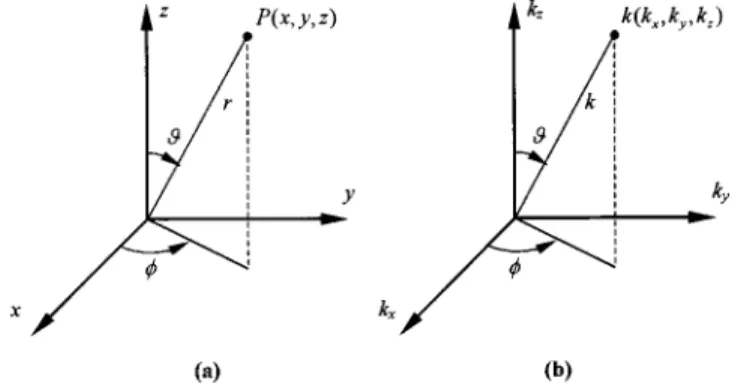
where kx⫽k sincos, ky⫽k sinsin, kz⫽k cos, r
⫽
冑
x2⫹y2⫹z2, r, , and are spherical coordinates 共Fig. 2兲, and V(kx,ky) is the spatial Fourier transform of(x,y ):V共kx,ky兲⬅
冕
⫺⬁ ⬁冕
⫺⬁ ⬁ 共x,y兲e⫺ j共kxx⫹kyy兲dx dy . 共11兲Equation 共10兲 implies that the far-field directivity of the source depends on the velocity spectrum on the wave num-ber space. Only the propagating modes inside the radiation circle (kx2⫹ky2⭐k2) contribute to the far-field radiation.
Classical theory of plate radiation has suggested a hy-drodynamic short circuit phenomenon: a flexible infinite panel has no acoustic output at frequencies below the coin-cidence frequency共Cremer and Heckl, 1988兲
c⫽c2
冑
D 共12兲
at which the speed of sound matches the speed of bending wave in a panel. However, this is not true for a ‘‘finite’’ panel and it is possible to have sound radiation below coin-cidence due to the aperture effect. A finite panel can be de-scribed by an aperture function
a共x,y兲⫽
再
1, 共x,y兲 inside aperture
0, 共x,y兲 outside aperture. 共13兲
By decomposing the flexural standing waves into traveling waves, the velocity distribution of the finite panel
⬘
(x, y ) can be approximated in terms of the velocity distribution of an infinite panel(x, y ),
⬘
共x,y兲⫽共x,y兲a共x,y兲. 共14兲In wave number space, this amounts to
V
⬘
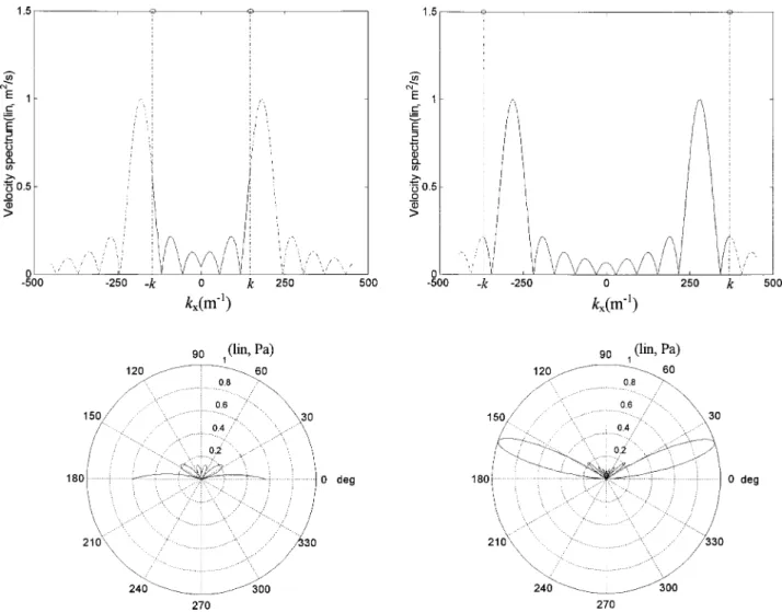
共kx,ky兲⫽V共kx,ky兲*A共kx,ky兲, 共15兲where ‘‘*’’ denotes convolution. Hence the aperture effect results in leakage of the wave number spectrum such that the panel could have nonzero acoustic output into the far field below coincidence共Panzer and Harris, 1998a兲. For example, a one-dimensional surface velocity distribution (x)
⫽cos(kbx) 共expressed as a standing wave due to boundary
effects兲 corresponds to the velocity spectra in wave number space and the radiation patterns shown in Fig. 3. Even though ideal hydrodynamic short circuit no longer exists in such case, the acoustic radiation at low frequency remains not as efficient as rigid pistons because of cancellations of volume velocity on the surface. In addition, it was pointed out by the reviewer that the presence of boundaries will cause only evanescent waves. The boundary effects are not considered in the above arguments in that the differences in the subsonic portion of the wave number spectra of the finite and infinite plate responses have no effect on the far-field radiation 共Junger and Feit, 1986兲.
III. SYSTEM MODELING AND SIMULATION
Simulation tools were developed to facilitate the design and integration of DML. These tools encompass two aspects: electro-mechanical modeling and acoustic radiation predic-tion.
A. Electro-mechanical modeling
Electro-mechanical equivalent circuit technique is em-ployed for modeling the panel-exciter system of a DML. The equivalent circuit 共mobility analogy兲 of a DML system is shown in Fig. 4共a兲. Although the equivalent circuit in Fig. 4共a兲 is in the form of graphic language, it is entirely based on Newton’s second law, Lorentz force, and Kirchhoff’s circuit laws. The details of how this circuit is derived are tedious but standard in literature, e.g., text by Beranek 共1996兲 and are thus omitted for brevity. In this figure, Zc⫽Rc⫹ jXc is
the electrical impedance of voice coil. Bl is the motor con-stant of the voice coil. Cs and Rs are the compliance and
damping, respectively, between the magnet and the panel. Mmis the mass of the magnet assembly. Mcis the mass of
the voice coil. Zmis the mechanical impedance of an infinite
panel at the driving point. Mf is the mass of the frame. Cp
and Rp are the compliance and damping of the suspension
between the panel and frame. Note that the constant real driving point impedance of Eq. 共7兲 for an infinite plate is used and radiation loading is neglected in the modeling. It has been pointed out by the reviewer that the force on the plate should be dependent on the impedance predicted by the finite element model. The ‘‘coupled’’ electrical-mechanical-acoustical systems should be solved simultaneously. For the present, this is somewhat impractical from the engineering standpoint. In this work, we are merely content with the frequency-independent impedance of an infinite plate. This is a reasonable simplification because only far-field radiation is of interest共so that evanescent waves due to boundary effects are negligible兲 and also the panel is much heavier than the diaphragms of cone speakers共so that acoustic loading is neg-ligible兲.
The equivalent circuit can be simplified into a Thevenin circuit of Fig. 4共b兲, where Vsis the voltage source, Zs is the source impedance reflected to the mechanical side, and ZLis
the mechanical impedance of the load including the panel and the exciter assembly. The force is determined with the attached driver assembly taken into account. In terms of the Laplace transform,
FIG. 2. Coordinate system for sound radiation analysis.共a兲 Spatial domain;
Vs共s兲⫽ N1共s兲 D1共s兲, 共16兲 where N1共s兲⫽Bl•Cs•Eg•Mms and D1共s兲⫽CsMmMcXcs3⫹共CsMmMcRc⫹CsMmRsXc ⫹CsMcRsXc兲s2⫹共Bl2CsMc⫹Bl2CsMm ⫹CsMmRsRc⫹CsMcRsRc⫹MmXc⫹McXc兲s ⫹共Mm⫹Mc兲Rc, 共17兲 Zs共s兲⫽ N2共s兲 D2共s兲, where N2共s兲⫽CsMmXcs3⫹共CsMmRc⫹Xc⫹CsRsXc兲s2 ⫹共Bl2C s⫹CsRsRc兲s⫹Rc and
FIG. 3. Sound radiation of a vibrating panel with an aperture 0.2 m. The figures in the upper part are the velocity spectra in wave number domain, while the figures in the lower part are the polar radiation patterns.共a兲 Below coincidence 共f ⫽8 kHz, kb⫽180 m⫺1, k⫽148 m⫺1兲; 共b兲 above coincidence 共f ⫽18 kHz,
kb⫽294 m⫺1, k⫽368 m⫺1兲.
FIG. 4. Electro-mechanical analogy of a DML.共a兲 Equivalent circuit 共mo-bility analogy兲; 共b兲 simplified circuit. The symbols f and u in the figures denote, respectively, the force and the velocity of the panel.
D2共s兲⫽s关CsMcMmXcs3⫹共CsMmMcRc⫹CsMmRsXc ⫹CsMcRsXc兲s2⫹共Bl2CsMm⫹Bl2CsMc ⫹CsMmRsRc⫹CsMcRsRc⫹MmXc⫹McXc兲s ⫹共Mm⫹Mc兲Rc, 共18兲 ZL共s兲⫽ 1 Zm p共s兲.
Thus the power delivered to the load ZL(⫽RL⫹ jXL) can be calculated as
WL⫽
兩Vs兩2RL
共Rs⫹RL兲2⫹共Xs⫹XL兲2
. 共19兲
In the work, a DML intended for multi-media applica-tion is examined. The parameters of the panel and exciter are listed in Table I. The simulation result of the exciter force f with a sinusoidal input of 1 V rms is shown in Fig. 5.
B. Prediction of acoustic radiation
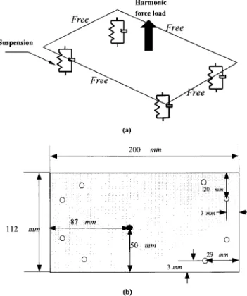
After the exciter force output f is determined, the surface velocity of the panel is calculated by the finite element method. A 200 mm⫻112 mm rectangular polyurethane 共PU兲 foam panel is examined. The locations of exciter and suspen-sions are shown in Fig. 6. From the finite element analysis, a sample surface velocity
⬘
(x,y ) of the panel is shown in Fig. 7共a兲.Having obtained surface velocity, one shall proceed with the calculation of far-field sound pressure p(x,y ,z) through the use of Eq. 共10兲. In this step, two-dimensional FFT is employed to obtain the surface velocity spectrum V
⬘
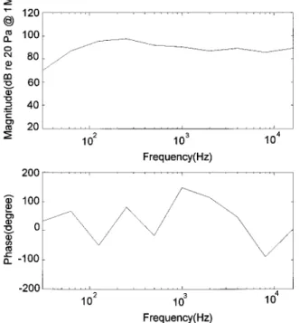
(kx,ky)in the wave number domain 关Fig. 7共b兲兴. In this step, zero-padding 共indicated in the figure兲 is used to improve resolu-tion in the wave number space. The frequency response of the vibrating panel between the force input and sound pres-sure output at 1 m distance is calculated共Fig. 8兲. Combining the frequency response functions in Figs. 5 and 8 leads to the overall frequency response from the voltage input to the sound pressure output at 1 m distance 共Fig. 9兲. In addition, directional response can also be calculated共Fig. 10兲. In some cases, the rms pressure within a band is required. This can be done by a straightforward integration:
prms⫽
冉
冕
f1 f2 兩p共 f 兲兩2•G xxd f冊
1/2 , 共20兲where f1and f2are the lower and the upper frequency limits, respectively, p( f ) is the frequency response between the voltage input and the sound pressure output, and Gxx is the
power spectrum density of the input voltage. TABLE I. Parameters of the panel and the exciter.
Parameters Panel Bending stiffness D⫽1.672 N•m
Area density⫽0.492 kg/m2 Dimension⫽0.2 m⫻0.112 m⫻0.002 m Poisson ratio⫽0.33
Mass of frame Mf⫽0.06 kg Panel mobility Zm p⫽7.255 N•s/m Damping of panel suspension Rp⫽0 N•s/m Compliance of panel suspension Cp⫽900⫻10⫺6m/N Exciter Impedance of voice coil Zc⫽4⫹ j•32⫻10⫺6⍀
Motor constant Bl⫽1.54 Wb/m
Compliance of coil suspension Cs⫽170⫻10⫺6m/N Damping of panel suspension Rs⫽0.257 N•s/m Mass of magnet Mm⫽37⫻10⫺3kg
Mass of coil Mc⫽0.35⫻10⫺3kg
FIG. 5. Predicted force response of the exciter with 1 V rms electrical input.
FIG. 6. Panel configuration for finite element analysis.共a兲 Panel driven by a harmonic concentrated force input. The panel is flexibly suspended with free boundaries;共b兲 dimensions of the panel and locations of the driving point
On the other hand, if sound power is of interest, the following formula can be utilized to calculate the power fre-quency response共Cremer and Heckl, 1988兲:
W共 f 兲⫽0ck 82
冕
⫺k k冕
⫺k k 兩V⬘
共k x,ky兲兩2冑
k2⫺kx 2⫺k y 2dkxdky, 共21兲 which entails again the surface velocity spectrum. A sample result of sound power is shown in Fig. 11. The total power within a band can be obtained from the following integra-tion:Wtotal⫽
冕
f1 f2
W共 f 兲•Gxxd f . 共22兲
IV. DESIGN PROCEDURE AND PERFORMANCE EVALUATION
A. Design procedures
The design procedures of DML are outlined as follows: 共1兲 Choose the area A of panel according to the specific application. In theory, a large area is preferable if effi-ciency is the major concern. In practice, however, the
choice relies largely on packaging or artistic consider-ation for the applicconsider-ation of interest. In our case, A ⫽0.0224 m2, which is typical for multimedia or note-book applications.
共2兲 Choose D/ ratio to achieve the fundamental frequency f0that is sufficiently low to produce reasonable low fre-quency response. The fundamental frefre-quency of an iso-tropic vibrating plate can be approximated by 共Leissa, 1993兲 f0⬇ A
冑
D . 共23兲 In our case, D/⫽3.3984 N•m3/kg, f0⫽258 Hz, c⫽64 177 rad/s. Small D, or small , should be selected for a small panel.
共3兲 Minimize the panel mechanical impedance Zm to
achieve acceptable efficiency by choosing appropriate density and Young’s modulus E. Note that
Zm⫽8
冑
D⫽16D
冑
3共1⫺2兲 3E. 共24兲
For good acoustical efficiency, the chosen panel should be stiff共large E兲 and light 共small兲, e.g., composite and FIG. 7. Surface velocity of the panel excited by a 1 N harmonic 共4 kHz兲 concentrated force. 共a兲 Spatial do-main;共b兲 wave number domain. Interior of the marked rectangle is the panel area; exterior of the marked rect-angle is padded with zeros for improving resolution in the wave number space.
honeycomb materials. Note thatis more critical than E in that Zmis inversely proportional to
冑
E/3.共4兲 Choose the aspect ratio of the panel. As mentioned pre-viously, flexural resonance is encouraged to excite as many as possible complex vibration modes in a panel. To this end, the vibration modes of panel are approxi-mated by the product of two sets of ‘‘beam’’ modes along each side of the panel 共Harris and Hawksford, 1997兲. For an Euler beam of length l, material constants D,, free at both ends, the resonance frequencies are
i⫽
冑
1 4D , i⫽1,2,3¯ , 共25兲 with i⫽冉
共2i⫺1兲 2l冊
, 1,2,3¯ .Complex vibration modes of a DML can be achieved by selecting an aspect ratio such that the beam modes along each side are best interleaved.
共5兲 Choose the driving point and suspension points of the panel. This can be done by a finite element based modal analysis. The driving point should be chosen at where the least nodal lines are, while the suspension points should be chosen at where the most nodal lines cross. 共6兲 Choose an exciter that matches the panel. A common
practice is to choose a large Bl constant for ensuring sufficient output level. This is preferably achieved by using strong magnet rather than increasing the length of coil because the latter approach has an adverse effect of increasing resistance and inductance. Next, choose a
FIG. 8. Predicted frequency response of the vibrating panel between the force input and sound pressure output at 1 m on-axis distance.
FIG. 9. Predicted overall frequency response of the DML between the volt-age input and sound pressure output at 1 m on-axis distance.
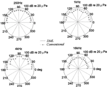
FIG. 10. Predicted directional response of the DML at 250, 1000, 4000, and 16 000 kHz for 1 W input.
FIG. 11. Predicted sound power frequency response of the DML for 1 V rms electrical input.
large magnet mass Mm and a small coil mass Mc
be-cause the bandwidth is dependent of the ratio Mm/ Mc
共Panzer and Harris, 1998b兲.
共7兲 Calculate the response by the aforementioned simulation procedures. From the simulation, one can get an idea of the performance of a DML before it is practically imple-mented.
B. Performance evaluation
To compare the DML with the conventional loud-speaker, experimental investigations were undertaken. A conventional multimedia loudspeaker共4⍀, 2 W, 6 cm diam-eter兲 for a desktop computer was used in the comparison. The area ratio between the DML and the conventional speaker is approximately 8 to 1. Both speakers are embedded in a 1.5 m⫻2.0 m baffle. The enclosure of the multimedia speaker has been removed. The use of baffle is to meet the requirement of far-field calculation using Fourier transform, where rigid baffled planar sources are assumed. The perfor-mance indices to be measured are summarized as follows 共Borwick, 1994兲.
1. Frequency response
The on-axis pressure responses at 1 m•W condition from the conventional speaker and the DML were measured in a semi-anechoic room such that the effect of room response can be minimized. Random noise band-limited to 16 kHz was used as the input. From the result of sound pressure spectral levels共Fig. 12兲, a significant gap 共maximum 15 dB re: 20 Pa at 1 m•W兲 can be seen between the response levels.
2. Directional response
The microphone is positioned along a semi-circle at angles from 0° to 180° with 10° increments. Figure 13 shows the measured directional response of the DML versus the conventional speaker. Only data in half space are shown be-cause both speakers are embedded in the baffle. The result indicates that DML yields an omni-directional response, even at high frequency共16 kHz兲. The conventional speaker does not show the kind of high frequency beaming because it is very small. If a larger DML were compared with a larger cone speaker, the contrast would be more apparent.
3. Sensitivity
The sensitivity of a speaker is defined as the free-field sound pressure level produced by 1 W electrical input, mea-sured at the on-axis distance 1 m. In our case, a random noise input of 2 V rms 共band-limited to 16 kHz兲 and nominal im-pedance of 4⍀ in the coil was used. The measured sensitivi-ties of the DML and the conventional speaker are 80.7 dB and 90.6 dB, respectively, re: 20Pa over a 16 kHz band.
4. Efficiency
The efficiency of a speaker is defined as the ratio of the radiated acoustic power to the electrical power input. In the work, ISO 3745 was employed for measuring the sound power in the semi-anechoic room共ISO standard, 1977兲. The
measured efficiencies of the DML and the conventional speaker are 0.039% and 0.089%, respectively. The result in-dicates the DML has a problem of sensitivity and efficiency in comparison with the conventional speaker. Poor radiation efficiency below coincidence frequency is a physical con-straint of flexible panels.
FIG. 12. The sound pressure spectral levels of the conventional speaker and the DML. The measurements are under 1 m•W condition. 共a兲 Bandwidth ⫽25.6 kHz; 共b兲 bandwidth⫽1.6 kHz.
FIG. 13. Directional responses of the DML and the conventional speaker at 250, 1000, 4000, and 16 000 kHz, respectively. The radial scales are in dB with a full scale 100 dB re: 20Pa.
5. Harmonic distortion
Harmonic distortion represents the ratio of the rms dis-tortion to the rms total signal. It can be calculated by mea-suring the rms total signal, using the same setup as for fre-quency response measurements and also that obtained when the driving frequency is filtered out. The harmonic distor-tions of the DML and the conventional loudspeaker mea-sured with a 2 V rms and 1 W electrical input at three fre-quencies are summarized in Table II. The DML appears to have higher harmonic distortion than the conventional speaker does. A possible explanation is that the DML relies on resonant modes of the panel, where nonlinearity may arise due to an exceedingly large amplitude of motion at resonance.
V. SYSTEM ENHANCEMENT
The foregoing comparison between the DML and the conventional speaker reveals that the DML suffers from the problem of poor sensitivity and efficiency. In this work, a practical solution is adopted in an attempt to alleviate the problem. Such approach involves the use of an electronically compensated woofer to supplement the low frequency re-sponse.
The system consists of a woofer cascaded with a feed-forward controller. The complete DML-woofer system is shown in Fig. 14共a兲. The design of the controller is based on a H2 model matching idea. The system block diagram is shown in Fig. 14共b兲, where T1is the desired response model,
the plant T2 is the woofer, and Q is the feedforward control-ler. In general, a low-pass filter with linear phase character-istics is selected as the model T1, which is essentially similar to the low frequency crossover in conventional woofer de-sign. The design problem is to find a proper and stable 共de-noted as RH⬁兲 transfer function Q such that the following cost function is minimized
J⫽ min
Q苸RH⬁
储T1⫺T2储22, 共26兲
where ‘‘储 储2’’ denotes the 2-norm defined as 储G共z兲储2,
冉
1 2冕
⫺ 兩G共ej兲兩2d冊
1/2 , 共27兲where z andare z-transform variable and digital frequency, respectively. It can be shown that the optimal solution of this problem is共Doyle et al., 1992兲
Q⫽T2m⫺1共T2a⫺1T1兲s, 共28兲
where T2m is the minimum phase part of T2, Ta2 is an all
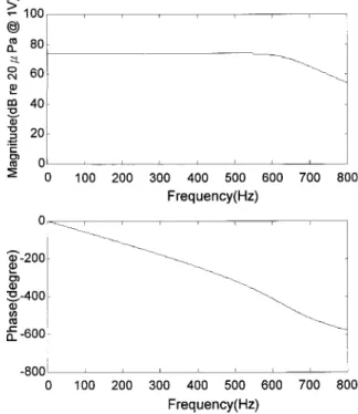
pass function and the subscript s denotes the ‘‘stable part.’’ In the paper, a ninth-order low-pass filter with cutoff frequency 600 Hz is chosen as the model T1 共Fig. 15兲. The frequency response of the plant is shown in Fig. 16. The
plant model was found by MATLAB command invfreqz
共Grace and Laub, 1992兲 and regenerated in the same plot. By using H2 modal matching, the optimal controller is calcu-lated, as shown in the frequency response of Fig. 17. The controller was then implemented on the platform of a floating-point DSP, TMS320C31, with a sampling rate of 2 kHz. Figure 18 compares the sound pressure frequency re-sponses of the DML alone, the DML with woofer, and the DML with bass-enhanced woofer. The experimental result demonstrated the significant improvement of overall perfor-mance by using the woofer and electronic compensation. TABLE II. Harmonic distortion of panel loudspeaker in comparison with
conventional loudspeaker. 250 Hz 1 kHz 4 kHz Conventional speaker 1.96% 0.91% 1.02% Panel speaker 3.25% 10.6% 12.6%
FIG. 14. The DML system enhanced by electronic compensation.共a兲 Inte-grated system of the DML and a woofer;共b兲 block diagram of the H2model matching method.
VI. CONCLUSIONS
In the paper, panel speakers were analyzed in terms of structural vibration and acoustic radiation. Simulation tools were developed to facilitate system integration of DML. The driving point impedance for an infinite plate is used and radiation loading is neglected in the modeling. Although this may be sufficient for the present study, a more sophisticated modeling approach dealing with the frequency dependent mechanical impedance and the associated radiation loading of a flexible finite plate should be developed in the future to improve the accuracy of response prediction.
In order to compare the DML with the conventional speaker, an objective evaluation regarding frequency re-sponse, directional rere-sponse, sensitivity, efficiency, and har-monic distortion was undertaken. Experimental results re-vealed that the DML suffered from an inherent problem of sensitivity and efficiency. To alleviate the problem,
elec-tronic compensation based on the H2model matching prin-ciple was developed. The experimental result demonstrated the improvement of overall performance by using the woofer and electronic compensation. Alongside with the other ad-vantages of DML, the enhanced efficiency should improve its practicality in applications where high audio quality is demanded.
Although the compensated woofer proved to be a prac-tical solution to the improvement of the overall efficiency, the bulky size of the woofer offsets somewhat the merits of DML. Furthermore, it should be noted that the efficiency problem of the DML alone has not been fundamentally changed in the present approach due to the physical con-straint of flexible panels imposed by the sub-coincidence phenomenon. To further improve the efficiency of panel speakers, planar radiators without resort to the mechanism of flexural waves should be sought in the future. To summarize, the major limitations of the present work are: the use of impedance of infinite plate, the neglect of acoustic loading in circuit modeling, and the bass compensation by a conven-tional woofer. Research is currently on the way to circum-vent these limitations.
ACKNOWLEDGMENTS
Special thanks are due to the illuminating discussions with New Transducers Limited, U.K. We also wish to thank Dr. William Thompson, Jr. of Applied Research Laboratory 共ARL兲, Penn State University for lectures on acoustic trans-ducers. The work was supported by the National Science Council 共NSC兲 in Taiwan, Republic of China, under the Project No. NSC 89-2212-E009-057.
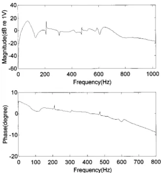
FIG. 16. Frequency response function of the plant. Solid line denotes the measured response and dash line the response regenerated from the curve fit model.
FIG. 17. Frequency response function of the H2feedforward controller.
FIG. 18. Frequency response function of the DML system before and after enhancement: DML共solid line兲, DML with woofer 共dash line兲, DML with enhanced woofer共dotted line兲. The measurements are under 1 m•W condi-tion.
Azima, H.共1998兲. ‘‘NXT Up against wall,’’ Audio Magazine, September, pp. 34–41.
Beranek, L. L.共1996兲. Acoustics 共Acoustical Society of America, Wood-bury, NY兲.
Borwick, J.共1994兲. Loudspeaker and Headphone Handbook 共Focal Press, Oxford, U.K.兲
Cremer, L., and Heckl, M.共1988兲. Structure-borne Sound 共Springer-Verlag, Berlin兲.
Doyle, J. C., Francis, B. A., and Tannenbaum, A. R. 共1992兲. Feedback Control Theory共Macmillan, New York兲.
Grace, A., and Laub, A. J.共1992兲.MATLABControl System Toolbox共Math Works, Natick, MA兲.
Harris, N., and Hawksford, M. O.共1997兲. ‘‘The Distributed-Mode Loud-speaker共DML兲 as a Broadband Acoustic Radiator,’’ The 103rd Conven-tion of Audio Engineering Society Preprint, New York, September 1997, No. 4526共D6兲.
ISO standard共1977兲. ‘‘Basic Array of Microphone Positions in Free Field over a Reflecting Plane,’’ ISO-3745-1977共E兲.
Junger, M. C., and Feit, D.共1986兲. Sound, Structures, and Their Interaction 共The MIT Press, Cambridge, MA兲.
Kinsler, L. E., Frey, A. R., Coppens, A. B., and Sanders, J. V. 共1982兲. Fundamentals of Acoustics共Wiley, New York兲.
Leissa, A. 共1993兲. Vibration of Plates 共Acoustical Society of America, Woodbury, NY兲.
Morse, P. M., and Ingard, K. U.共1986兲. Theoretical Acoustics 共Princeton University Press, Princeton, NJ兲.
Panzer, J. W., and Harris, N.共1998a兲. ‘‘Distributed-Mode Loudspeaker Ra-diation Simulation,’’ The 104th Convention of Audio Engineering Society Preprint, New York, No. 4783.
Panzer, J. W., and Harris, N. 共1998b兲. ‘‘Distributed Mode Loudspeaker Simulation Model,’’ The 104th Convention of Audio Engineering Society Preprint, New York, No. 4739.