Wavelength Tunable Semiconductor Laser with a Liquid Crystal Pixel
Mirror
Ru-Pin Pan
a, Hsiu-Chi Tung
a, Chia-Rong Sheu
a, Ci-Ling Pan
b, and Ming-Jay Huang
b,
aDepartment of Electrophysics, Institute of Electro-Optic Engineering, and the Lee-MTI Center
National Chiao Tung University, 1001 Ta-Hsueh Rd., Hsinchu, Taiwan 30010, R.O.C.
contact: [email protected]; [email protected]
ABSTRACTTunable semiconductor lasers are compact, versatile sources used extensively in dense-wavelength-division-multiplexing (DWDM) optical communication systems, precision metrology, environmental monitoring, and laser spectroscopy. We have developed a twisted nematic liquid crystal device, the liquid crystal pixel mirror (LCPM), successfully as electronically tunable spectral filters for wavelength selection in external cavity semiconductor lasers. In this talk, we report recent advances in this class of electronically tunable single- and multiple-wavelength semiconductor lasers at 650 and 830 nm. Preliminary results of operating the laser at 1.5 microns will also be shown. The laser output can be locked to the ITU grid at 100 GHz intervals. Output power of the laser is as high as several hundred milliwatts, with a tuning range of several tens of nanometers. The laser can be operated either in the continuous-wave (CW) or mode-locked configuration. The linewidth of the laser in the free-running CW mode is about 30 MHz. Fine-tuning of the cw output wavelength can be achieved by changing the driving voltage to the desired pixels of the LCPM. In the mode-locked configuration, the laser design allows intra-cavity dispersion compensation and pulse compression.
Keywords:
Laser tuning, Semiconductor Laser, Liquid crystal devices, Narrow LinewidthINTRODUCTION
Tunable semiconductor and fiber lasers are compact, versatile sources used extensively in dense-wavelength-division-multiplexing (DWDM) optical communication systems, precision metrology, environmental monitoring, and laser spectroscopy. These lasers were typically tuned with bulk and fiber-type gratings, Fabry-Perot Etalon or
interference filters, as well as electro-optic or acousto-optic tunable filters.1 In particular, a number of liquid crystal (LC)
devices have been developed successfully as electronically tunable spectral filters for wavelength selection in lasers and
related WDM system components.2-7 These LC devices are either of the birefringent filter type2,4,5 or have the
Fabry-Perot structure3,7. The other approach, reported by Parker and Mears6, employed holographic gratings electro-optically
written on a ferroelectric liquid crystal spatial light modulator together with a fixed phase grating to tune the wavelength of a fiber laser to discrete wavelength spaced by 1.3 nm. We reported electronic tuning the wavelength of
a laser diode in a pointer over 3 nm by using a liquid crystal pixel mirror (LCPM)8 in a folded telescopic
grazing-incidence grating-loaded external cavity9,10. Narrow-band (< 0.1 nm, instrument limited) digital wavelength tuning
and switching of an AR-coated red semiconductor laser over 14 nm was realized.11, 12 We also presented dual- and
triple-wavelength generation from this laser. Employing a broad-area semiconductor laser as the gain medium, we
demonstrated relatively high-power multiple-wavelength generation successfully.13 Our laser cavity design can also be
adapted to construct a wavelength-selective optical filter or switch.14 In this paper, the basic laser configuration and
operation principles are reviewed. We will also present recent advances such as fine-tuning of the laser wavelength, injection amplification and mode locking. The same laser configuration can be modified for operation in the 1550 nm band, which is important for optical communication. Preliminary results are shown.
BASIC LASER CONFIGURATION
A schematic of the laser is shown in Fig.1. This is a folded telescopic grazing-incidence grating-loaded external cavity. A laser diode (LD) with AR-coated front facet and HR-coated back facet was used as the gain
medium. In mode-locked operation, the LD was biased both with a DC current and modulated with RF signal from a frequency synthesizer at a frequency optimized for active mode-locking (f ~ 600 MHz) and a power of about 0.5 W. Output from the AR-coated front facet of the LD was collimated and incident on a grating (2400 , 1800 or 1200 lines/mm for LD’s with gain center wavelengths of 650 nm, 830 nm and 1550 nm respectively) at the grazing angle. The retro-reflected first-order-diffracted light from the grating, which was collected by a lens (f = 15 cm) and focused on the liquid crystal pixel mirror (LCPM), provides the wavelength-selective optical feedback required for laser operation.
The LCPM is based on the design of a normally off-state twisted nematic liquid crystal (NLC) cell (See Fig.2). The cell was
constructed with a 6-µm-thick NLC (E7+1% 0f
C15 from E. Merck) layer sandwiched between indium-tin-oxide (ITO) glass plates. One of the ITO-electrodes was patterned. The pattern
consisted of fifty 100 µm × 2 cm stripes with 5
µm spacing. The back mirror was an Au-coated
silicon substrate. The width of the pixel was chosen such that only one mode of the bare diode chip was selected. The polarizer was aligned to transmit light parallel to that of the incident laser polarization. The laser is electronically tuned and switched by biasing the individual pixels,
with wavelength steps ∆λ determined by
center-to-center separation of the adjacent pixels ∆x,
∆λ = Λcosθr ∆x/f, (1) where Λ is the grating period; θr is the first-order diffraction angle; f is the focal length of the lens. The primary laser output is the zeroth-order reflection of the grating (~ 60% of the incident light from the diode chip).
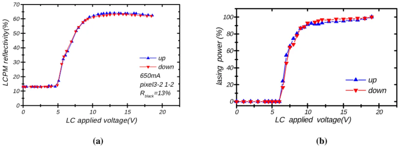
The contrast ratio and on state reflectivity of the homemade LCPM were about 5:1 and 64% respectively. The reflectivity of the LCPM itself and the corresponding relative laser output power with the LCPM in the cavity are plotted as a function of the applied voltage in Fig.3(a) and (b). Upright and inverted triangles correspond to data obtained when the applied voltage was ramped up or down. The light source was an AR -coated broad-area laser diode
(λ = 830 nm)
operating below threshold (i.e., LED mode). Because of high gain of the semiconductor media, thereflectivity and contrast of the LCPM are sufficient achieve the desired spectral filtering function. The threshold
switching voltage of the LCPM is 5 Vpp (peak-to-peak) at 1 kHz. Complete switching from off-state to on-state is
achieved at 10Vpp.
Our laser cavity design has several advantages: In contrast to conventional designs such as Littrow and Littman types, it allows selective feedback and generation of multiple wavelengths. The output at different wavelengths are co-axial and of the same polarization. Further, the grating-lens-LCPM combination is just a folded telescopic dispersive delay line used extensively for ultrafast laser pulse shaping. Zero dispersion corresponds to the case of gratings and lens configured in a 4-f imaging setup. By adjusting the gratings relative to the lens, either positive or negative dispersion can be generated to compensate for group velocity dispersion in the cavity and shorten
Fig.1 A schematic of the basic configuration of the laser. LCPM: liquid crystal pixel mirror.
Gold-coated silicon substrate (mirror)
Polarizer Glass
Incident laser beam Patterned ITO
NLC
W/SA ITOW/SA
Fig.2 Configuration of the LCPM: ITO: indium-tin-oxide coating; NLC: nematic liquid crystal; SA: surface alignment layer.
the laser pulses. Amplitude and phase masks in the form of a spatial light modulator placed at the image plane of the lens allow compensation of higher-order chirp in the laser pulse and generation of arbitrary pulse shapes for applications such as coherent control of quantum states.
ADVANCES IN CW TUNABLE OPERATION
In this section, we summarize the salient features of the laser operating in the cw mode. First of all, the laser
performance of a system using a low-power AR-coated red laser diode (Sacher-650-3, λ≈ 650 nm, 3 mW before
AR-coating) is presented. Figure 4 illustrate the narrow-band (< 0.1 nm, instrument limited) output of the laser as measured by an optical spectrum analyzer (Anritsu, model MS9030). The laser wavelength can be tuned discretely in 0.21 nm steps by biasing sequentially the 50 pixels. At I
= 72.3 mA (or 1.54 Ith), the tuning range was
10.4 nm with λ = 650.8 nm for pixel #1 and λ =
661.24 nm for pixel # 50. The tuning range was limited by the number of pixels available for the
present LCPM. At I = 1.54 Ith, the shortest and
longest wavelengths that could be operated were 650.04 nm and 664.04 nm, respectively. The side-mode-suppression-ratio (SMSR) of the laser was better than 25 dB throughout this range. In Fig.5, we plot the lasing wavelength as a function of the pixel number. It is in good agreement with the theoretical prediction according to Eq. (1). The wavelength repeatability of the present laser is excellent. After switching to a different pixel, the laser wavelength is reset. Realignment of the laser cavity is not necessary.
In the wavelength-switching experiment, the 10kHz biasing signal was alternately applied to pixel # 13 (λ1= 653.2
nm) and # 25 (λ2= 658.48 nm). These switching waveforms are shown as trace 1 and 3 of Fig.6. A second grating
was used to angularly disperse the co-axial laser output at λ1 and λ2, which were monitored by two photodiodes.
These are shown as traces 3 and 4 in Fig.6. Wavelength switching is clearly demonstrated. The switch-on time, the time it takes for a pixel to change from an off state to an on state, is ~ 13.6 ms. The switch-off time was ~ 54.6 ms. these time constants were primarily determined by the dynamic characteristics of the twisted NLC cell.
0 5 10 15 20 0 10 20 30 40 50 60 70 up down 650mA pixel3-2 1-2 Rblack=13% LC P M r e fl e c ti v ity (% ) LC applied voltage(V) 0 5 10 15 20 0 20 40 60 80 100 up down la si ng pow e r (% ) LC applied voltage(V) (a) (b)
Fig. 3 (a) The reflectivity of LCPM vs. applied peak to peak voltage (Vpp), and (b) the relative lasing power vs. Vpp..
0.650 0.655 0.660 -60 -50 -40 -30 -20 Re la ti v e P o w e r (d Bm ) Wavelength (µµµµm)
Fig.4 Typical narrow-linewidth (< 0.1 nm, instrument-limiteed) output spectra of the tunable laser diode (λ = 650m) by biasing one of the pixels (50 in total) of the LCPM.
Figure 7 illustrates tunable dual-wavelength generation with wavelength separation tunable from 0.21 nm to 10. 4 nm. The two wavelengths are symmetric with the line center of the gain profile. Triple-wavelength generation with symmetric wavelength separation is shown in Figs.8. An example of generation of three arbitrary wavelengths is given in Fig.9.
Next, we show results obtained by using an AR-coated broad-area laser diode (LD, SDL2360, nominal
wavelength, λ≈ 830 nm) as the gain element. With the LD biased at a current of I = 450 mA (or 1.25 Ith), the single
wavelength digitally tunable range of the laser was from 828.48 nm (pixel #1) to 836.6 nm (pixel #50) in 0.16 nm steps with an average power of 25 mW. This is shown in Fig.10. The numbers of pixels in the LCPM limited the tuning range to 8.12 nm for the case presented here. As can be seen from Fig.10, the laser linewidth is less than 0.1 nm as determined by an optical spectrum analyzer. The side-mode-suppression-ratio (SMSR) of the laser was better than 25
dB throughout this range. The maximum possible tuning range at I = 1.54 Ith was 19 nm. The wavelength
repeatability of the present laser is also excellent. Figure 11 shows a high-resolution spectrum of the single-wavelength laser using a confocal Fabry-Perot Interferometer with a free spectral range of 2 GHz and resolution of 8.5 MHz. The laser linewidth was ~ 35 MHz. This is comparable to conventional external-cavity semiconductor lasers
0 5 10 15 20 25 30 35 40 45 50 652 654 656 658 660 662 664 theoretical curve experimental values W a v e le ngth ( n m) pixel number
Fig.5 Lasing wavelength as a function of the pixel number. The solid line is the theoretical curve according to Eq. (1). The solid squares are experimental data.
Fig.6 Wavelength-switching performance of the laser. Trace 1 and trace 2 are switching voltage waveforms applied to two pixels of the LCPM. Trace 3 and 4 are laser output
0.645 0.650 0.655 0.660 0.665 0.670 -100 -90 -80 -70 -60 -50 -40 -30 -20 I=1.54Ith ∆λmax=10.4nm ∆λmin=0.2nm Rel a ti ve P o w e r( d B m ) Wavelength(µµµµm)
Fig.7 Tunable dual-wavelength performance of the laser with symmetric wavelength separation between the two lasing wavelengths. 0.645 0.650 0.655 0.660 0.665 0.670 -100 -90 -80 -70 -60 -50 -40 -30 -20 I=1.54Ith R e la ti v e P o w e r (d B m ) Wavelength (µµµµm)
Fig.8 Triple wavelength generation with the two outer wavelengths symmetric with respective to the center wavelengths.
without active cavity control. We were able to fine-tune the laser wavelength by varying the voltage applied to the pixel. This changes the index of refraction of the liquid crystal and therefore the cavity length. The differential tuning rate was ~ 83.3 MHz/volt. The laser output power fluctuation is less than 1 dB over a period of several hours. The present laser is cable of generating single-wavelength output with hundreds of milliwatts. With the LD biased at
3.24 Ith, the output power was as high as 118 mW. The SMSR remained higher than 20 dB ( See Fig.12).
By biasing two pixels at the same time, we obtain dual-wavelength output with wavelength separation, ∆λ,
tunable from 0.16 nm (for the neighboring pixels, #25 and #26) to 8.12 nm (for the two outermost pixels, #1 and #50). This is shown in Fig.13. As an alternative approach to high-average power generation, we have also demonstrated injection amplification. The dual-wavelength case is illustrated in Fig.15. In this experiment, the master laser was biased at 500 mA, while the slave laser was biased at 766 mA. Because of a mismatch in the center wavelengths of gain profiles of the master and slave lasers, the output powers of the two wavelengths after injection amplification were not equal. Generation of tunable triple wavelengths with the two outer wavelengths symmetric with respect to the center wavelength was also realized (see Fig.16).
0.645 0.650 0.655 0.660 0.665 -90 -80 -70 -60 -50 -40 -30 I=1.54Ith R e la ti ve P o w e r (d B m ) Wavelength (µµµµm)
Fig.9 Generation of triple-wavelengths with arbitray wavelength separation. 0.826 0.828 0.830 0.832 0.834 0.836 0.838 -40 -35 -30 -25 -20 -15 -10 -5 0 I=1.25Ith Re la ti v e Po we r( d B m ) Wavelength(µµµµm)
Fig.10 Narrow-linewidth output spectra of the tunable broad-area laser diode (biased at 1.25 Ith) by turning on successive
pixels (50 in total) of the LCPM.
0.01 0.02 0.03 0.04 0.05 0.06 0.07 -0.015 -0.010 -0.005 0.000 0.005 0.010 0.015 0.020 V o lt age ( V ) F a b ry -Pe ro t Si g n a l (V ) time (sec) 4 6
Fig.11 Laser output spectrum as measured by a confocal Fabry-Perot Interferometer. The triangular waveform is that of the scanning voltage of the FPI.
826.26 828.26 830.26 832.26 834.26 -55 -50 -45 -40 -35 -30 -25 -20 -15 Re la ti v e P o w e r (d Bm) wavelength(nm)
Fig.12 High-power single-wavelength generation by biasing the LD at 3.24 Ith. The SMSR remains better than
We have also demonstrated operation of this laser configuration at 1550 nm. General characteristics are similar to that of the visible and near IR lasers. Figure 17 illustrates single-wavelength tuning behavior. The side-peaks are due to lasing by the chip mode, because of the relative poor AR-coating of the laser diode used. Dual-wavelength and triple-wavelength operations are shown in Fig.18 and 19, respectively. The wavelength separation for the dual-wavelength case was 0.67 nm. This is less than the 100 GHz frequency separation required by the ITU grid. In the
0.826 0.828 0.830 0.832 0.834 0.836 0.838 -35 -30 -25 -20 -15 -10 -5 0 R e la ti ve O u tput P o w e r (d Bm ) Wavelength (µm)
Fig.13 Dual-wavelength output spectra of the tunable laser diode. The two wavelengths are arranged to be symmetric with respect to the center wavelength of the gain bandwidth.
1-D stage Master Laser System Cylindrical Lens f=10cm Cylindrical Lensf=5cm to diagnostic Isolator OFR IO-5-NIR-HP
half wave plate PBS (Polarization Beam Splitter)
Slave Laser Diode to diagnostic
Ag mirror Ag mirror Ag mirror 40X Objective Lens Newport F-L40B pinhole Beam Splitter T=55%
pinhole Cylindrical Lens f=10cm Cylindrical Lensf=7.5cm
Fig.14 Experimental setup of the injection
amplification experiment. Both the master and slave lasers employed broad-area devices.
824 826 828 830 832 834 1E-11 1E-10 1E-9 1E-8 1E-7 m aster 500m A wavelength(nm ) pow er (d Bm ) 824 826 828 830 832 834 1E-8 1E-7 1E-6 slave 766m A wavelength(nm ) pow er (d Bm ) 824 826 828 830 832 834 1E-11 1E-10 1E-9 1E-8 1E-7 master 500mA wavelength(nm ) pow er (d Bm ) 824 826 828 830 832 834 1E-8 1E-7 1E-6 slave 766m A wavelength(nm ) pow er (d Bm )
case of dual-wavelength output, we found that the power stability of the laser, Δp/p was better than 1 part in 104 over a period of two hours. The data are shown in Fig.20.
0.826 0.828 0.830 0.832 0.834 0.836 0.838 -35 -30 -25 -20 -15 -10 -5 Re la ti v e O u tp u t P o we r( d B m ) Wavelength (µm)
Fig.16 Triple-wavelength output spectra of the tunable laser diode. The two outer wavelengths are arranged to be symmetric with respect to the center wavelength of the gain bandwidth.
1525 1530 1535 1540 1545 1550 -90 -80 -70 -60 -50 -40 Iop=130mA=2 Ith Top=21o c out pu t power ( d B m ) wavelength (nm)
Fig.17 Single-wavelength tuning characteristics of a 1550nm laser. 1520 1525 1530 1535 1540 1 -90 -80 -70 -60 -50 -40 ∆λ=0.67 nm λshort=1532.02 nm λlong =1532.69 nm o u tput pow er ( d B m ) wavelength (nm)
Fig.18 Dual-wavelength operation of a 1550nm laser. The wavelength difference was 0.67 nm.
1525 1530 1535 1540 1545 -90 -85 -80 -75 -70 -65 -60 -55 Iop=110mA=1.75Ith λ1=1531.82 nm λ2=1533.54 nm λ3=1536.69 nm λ1=1528.18 nm λ2=1533.54 nm λ3=1536.66 nm λ1=1528.18 nm λ2=1534.42 nm λ3=1535.02 nm λ3 λ2 λ1 out put p o w e r (d B m ) wavelength (nm)
Fig.19 Triple-wavelength generation of the laser with arbitrary wavelength separation.
MODE-LOCKED TUNABLE OPERATION
Electronically tunable, single-and multiple-wavelength mode-locked operations of the laser have been realized for
the first time, to our knowledge. We employed the broad-area LD (λ = 830 nm) as the gain element and the laser was
actively mode-locked. With the LD biased at a DC current of 460 mA (Ith = 380 nm) and injected with 2 W of AC
signal at ~ 600 MHz (the 5th harmonic of the cavity resonance), the single-wavelength mode-locked tuning range was 5.
94 nm (6.16 nm for the CW case). The laser pulse waveform and spectrum are shown in Fig.21 and 22 respectively. The shortest laser pulse width generated by adjusting the intra-cavity dispersion was 23.4 ps. The time-bandwidth product was 0.614, or 1. 23 times of the transform-limited value assuming Gaussian pulse shapes. Generation of as many as 20 different wavelengths simultaneously was achieved (See Fig.23).
-500 0 500 1000 1500 2000 2500 3000 3500 4000 -0.20 -0.15 -0.10 -0.05 0.00 0.05 0.10 λ1=1529nm λ2=1547.36nm ( ∆ P/ P )λ1 (% ) time (sec) -0.20 -0.15 -0.10 -0.05 0.00 0.05 0.10 ( ∆ P/ P )λ2 (% )
Fig.20 Stability of the output power of the 1550 nm laser over a period of one hour.
823 824 825 826 827 828 829 830 831 832 833 834 -75 -70 -65 -60 -55 -50 -45 -40 IDC=460mA RF Power=34dBm RF Frequency=595.1MHz λc=828.85nm SMSR>25dB Opt ic a l Pow e r( dBm ) wavelength(nm)
Fig.21 Output spectrum of the single-wavelength actively mode-locked laser (λ = 826.86 nm). The SMSR of the laser was better than 25 dB.
Fig.22 The waveform of the pulse train generated by the single-wavelength actively-mode-locked laser. A NewFocus 1006 high speed detector and a HP54740A Oscilloscope were used for detection. 824 826 828 830 -70 -65 -60 -55 -50 -45 -40 20λ O p ti c a l p o we r(d B m ) wavelength(nm) pixel #=10-29 ∆λ=0.11nm
Fig.23 Output spectrum of the mode-locked broad-area laser simultaneously generating 20 wavelengths by biasing pixels 10 through 29. The wavelength separation was 0.11 nm.
For the experiment described above, the laser output power was 10 mW. To realize higher average power, injection amplification was pursued. The experimental setup is shown in Fig.14. Over a period of 10 nm around the line center, the amplifier gain was wavelength-independent. This is shown for the case of slave laser biased at 800 m A (See Fig.24). Pulse broadening due to amplification was also negligible. Results of injection amplification of a triple-wavelength master laser are presented in Fig.25. Note that the SMSR’s of the pulse spectra at the three wavelengths are all about 25 dB. This is in contrast to that of the master laser, of which the SMSR were 15, 33 and 33 dB respectively. Apparently, this approach allows spectral gain equalization of the signal. For optical communication systems, it is a very useful feature. After amplification, the average laser output power can be as high as several hundred mW. This laser source is therefore potentially useful for many applications in ultrafast optics and nonlinear optics.
SUMMARY
Recently, we have developed a twisted nematic liquid crystal device, the liquid crystal pixel mirror (LCPM), successfully as electronically tunable spectral filters for wavelength selection in external cavity semiconductor lasers. In this paper, we report recent advances in this class of electronically tunable single - and multiple-wavelength
semiconductor lasers at 650 and 830 nm and 1550 nm. Output power of the laser is as high as several hundred milliwatts, with a tuning range of several tens of nanometers. The laser can be operated either in the continuous-wave (CW) or mode-locked configuration. The linewidth of the laser in the free-running CW mode is about 30 MHz. Fine-tuning of the cw output wavelength can be achieved by changing the driving voltage to the desired pixels of the LCPM. In the mode-locked configuration, the laser design allows intra-cavity dispersion compensation and pulse compression. Generation of picosecond pulses simultaneously at 20 wavelengths is demonstrated for the first time. Using injection amplification, the average output power can be as high as several hundreds of milliwatts.
ACKNOWLEDGEMENTS
This work was supported by the National Science Council of the ROC under various grants, the Lee-MTI Center of NCTU, and the Radiantech Corporation. Ci-Ling Pan was also supported by the Pursuit of Academic Excellence Program of the Ministry of Education of ROC.
REFERENCES
1. P. Zorabedian, “Tunable External-Cavity Semiconductor Lasers,” in F. J. Duarte, ed., Tunable Lasers Handbook, Academic Press, San Diego, 1995, pp.349-442, and references therein.
8 24 8 25 8 26 8 27 8 28 8 29 8 30 1 6 1 8 2 0 2 2 2 4 2 6 2 8 3 0 3 2 3 4 3 6 3 8 4 0 Ga in (d B ) w a ve len gth(n m ) G ain o f M od e-lo cking Pu lse Injection Inje ctio n Ave rage Pow e r=0.7m W ID C of Sla ve l LD =80 0m A (a bo ve Th resho ld)
Fig.24 Gain of the slave laser versus wavelength.
824 825 826 827 828 829 830 831 832 -75 -70 -65 -60 -55 -50 -45 O p ti c a l P o we r( d B m ) wavelength(nm)
2. J. R. Andrews, “Low voltage Wavelength Tuning of an External Cavity Diode Laser Using a Nematic Liquid Crystal -Containing Birefringent Filter”, IEEE Photon. Technolog. Lett., vol. 2, No. 5, pp. 334-336, May 1990.
3. M. W. Maeda, J. S. Patel, D. A. Smith, Chinlon Lin, M. A. Saifi, and A. Von Lehman, “An Electronically Tunable Fiber Laser with a Liquid-Crystal Etalon Filter as the Wavelength-Tuning Element”, IEEE Photon. Technolog. Lett., vol. 2, No. 11, pp. 787-789, Nov. 1990.
4. B. Wacogne, J. P. Goedgebuer, A. P. Onokhov, and M. Tomilin, "Wavelength tuning of a semiconductor laser using nematic liquid crystals" IEEE J. Quantum Electron., QE-29, No. 4, pp. 1015-1017, 1993.
5. P. Mollier, V. Armbruster, H. Porte, And J. P., Goedgebuer, "Electrically tunable Nd3+-doped fibre laser using nematic liquid crystals", Electron. Lett., vol. 31, pp. 1248-1250, 1995.
6. M. C. Parker and R. J. Mears, “Digitally Tunable Wavelength Filter and Laser”, IEEE Photon. Technolog. Lett., vol. 8, No. 8, pp. 1007-1008, Aug. 1996.
7. S Matsumoto, M Hirabayashi, S, Sakata, and T. Hayashi, “Tunable Wavelength Filter Using Nano-Sized Droplets of Liquid Crystal”, IEEE Photon. Technolog. Lett., Vol. 11, No. 4, pp. 442-444, Apr. 1999.
8. Ci-Ling Pan, Shan-Huang Tsai, Chia-Rong Sheu, and Ru-Pin Pan, “Tunable diode laser with a liquid crystal spatial light reflector in a grating-loaded external cavity,” presented at the International Liquid Crystal Conference (ILLC’98), Strasbourg, France, July 19 – 24, 1998.
9. Chi-Leun Wang and Ci-Ling Pan, "Tunable Dual-wavelength Operation of a Diode Array with an External Grating-loaded Cavity", Appl. phys. Lett. Vol. 64, No. 23, pp. 3089 - 3091, June 6, 1994.
10. Chi-Luen Wang and Ci-Ling Pan, "Tunable Picosecond Pulse Generation from an Actively Mode-locked Laser Diode Array with Intracavity Chirp Compensation,' Jpn. J. Appl. Phys., vol. 33, pt. 2, No. 11, pp. L1456 - L1458, Nov. 1994.
11. Ci-Ling Pan, Ru-Pin Pan, Wen-Li Lu, and Chia-Reng Sheu, "Electronically Tunable Multiple Wavelength Semiconductor Laseer by Using a Liquid Crystal Pixel Mirror" presented at the 18th International Liquid Crystal Conference., Sendai International Center, Sendai, Japan, July 24 – 28, 2000, paper 25D-24-P, p/ 297.
12. Ru-Pin Pan, Chia-Reung Shieu, Wen-Li Lu, Ming-Jay Huang, and Ci-Ling Pan, “Wavelength tuning and multiple wavelength generation using a reflection-type liquid crystal spatial light modulator,” presented at the SPIE Annual Meeting, 29 July – 3 August, 2001, San Diego, California, to be published in Proceedings of the SPIE, Vol. 4457, Spatial Light Modulators:
Technology and Applications.
13. Ru-Pin Pan, Wen-Li Lu, Chia-Rong Sheu, and Ci-Ling Pan, “Electronically Tunable Single- and Multiple- Wavelength Broad-Area Semiconductor Laser,” in 2000 IEEE/LEOS Annual Meeting Conference Proceedings, 13-16, November 2000, The Westin Rio Mar Beach, Puerto Rico, paper ThP 6, pp. 830-831.
14. Ru-Pin Pan, Xiou-Xhi Tung, Jun-Yu Chen, Ming-Jay Huang, and Ci-Ling Pan, “Liquid-crystal-based tunable optical filtering devices for DWDM,” presented at ITCom2001, 19-24 August 2001, Denver, Colorado, USA, to be published in Proceedings of the SPIE, Vol. 4532, Active and Passive Optical Components for WDM Communication.