國立交通大學
材料科學與工程學系
博士論文
中孔洞材料在二氧化碳捕獲與藥物釋放之研究
Mesoporous Materials on CO
2Capture and Drug Delivery
研 究 生:張彥博
指導教授:陳三元 博士
中孔洞材料在二氧化碳捕獲與藥物釋放之研究
Mesoporous Materials on CO
2Capture and Drug Delivery
博 士 生:張 彥 博 Student:Yen-Po Chang 指 導 教 授:陳 三 元 博士 Advisor:Dr. San-Yuan Chen
國 立 交 通 大 學
材 料 科 學 與 工 程 研 究 所
博 士 論 文
A Thesis
Submitted to Department of Materials Science and Engineering College of Engineering
National Chiao Tung University In partial Fulfillment of the Requirements
For the Degree of Doctor of Philosophy
in
Materials Science and Engineering July 2012
Hsinchu, Taiwan, Republic of China
中文摘要
本論文中,使用各種不同的合成技術,其中包括溶膠-凝膠法、水熱尿素反應、微 波 輔 助 合 成 法 以 及 固 態 反 應 開 發 出 多 功 能 性 中 孔 洞 奈 米 結 構 材 料 (CaO/CaAlO, C12Al14O33, Gd2O3, TiO2)。使用粉末 X 光繞射儀(PXRD)、穿透式電子顯微鏡/電子能量
損失光譜 (TEM/EELS)、掃瞄式電子顯微鏡/X 光能量分散光譜儀(SEM/EDS)、傅氏轉 換紅外線光譜(FTIR)、氮氣吸附等溫線(N2 adsorption isotherm) 詳細地鑑定這些材料的
組成、形貌、化學結構以及多孔結構。這些中孔洞奈米結構材料的合成機制將於各章 節中被討論。本研究的中孔洞材料的孔徑大小為2-50 奈米範圍內。由於它們具有高表 面積與奈米孔洞結構的諸多優點,在二氧化碳捕獲與藥物釋放領域分別可以被設計為 一種高溫吸附劑或藥物載體。 在先期研究發現 (如附錄-1),首先採用水熱共沉法合成出二種不同金屬混合之金 屬氧化物(MgAlO、CaAlO、SrAlO),並且在高溫(200-850 oC)二氧化碳補捉實驗證實, CaAlO 金屬氧化物最適合作為高溫二氧化碳吸附劑(600-700 oC)。因此,使用水熱尿素 法來合成中孔洞金屬氧化物(CaO/CaAlO),此材料具有高表面積、均一孔洞結構及均 勻的奈米氧化鈣分佈,經由熱重分析(TGA)或固定床反應器(fixed-bed reactor)同時進行 二氧化碳補捉實驗,結果證實中孔洞奈米材料具有高二氧化碳吸附容量,快速吸附性 和長循環壽命。更進一步,使用微波輔助合成法進行中孔洞CaAlO 金屬氧化物合成, 由粉末 X 光繞射與電子顯微鏡證明,在低於 600 oC 的固態反應後可以形成結晶性 C12Al14O33奈米棒成長在奈米孔洞CaAlO 基質表面上。此材料具有多孔結構與高熱穩 定性,未來可以作為催化劑或二氧化碳吸附劑之載體。 另外,本研究採用溶膠-凝膠法合成出中孔洞氧化釓(Gd2O3)奈米管及中孔洞二氧 化鈦(TiO2)奈米薄膜,兩者材料可作為藥物載體並使用於藥物釋放控制。此材料鑑定 具有高表面積、多孔洞結構與高結晶性的奈米骨架。中孔洞氧化釓奈米管表現出微弱 的超順磁特性,能夠攜帶布洛芬(IBU)藥物,並且通過外部磁場控制方式進行藥物釋 放。另外,二氧化鈦薄膜具有蠕蟲狀中孔洞結構,使用布洛芬(IBU)和萬古黴素(VAN)
作為藥物模型分子,測定與薄膜化學相關持續藥物釋放。除此之外,體外骨細胞的黏 附行為和氫氧基磷灰石形成,證明此薄膜也具有細胞相容性和生物活性表現。
Abstract
In this dissertation, multi-functionalized mesoporous nanostructured materials (such as CaO/CaAlO, C12Al14O33, Gd2O3, and TiO2) have been prepared through various synthesized
routes, which include sol-gel method, hydrothermal urea reaction, microwave-assisted synthesis, and solid-state reaction. The composition, morphology, chemical structure, and porous structure of these materials were identified in detail using powder X-ray diffraction (PXRD), transmission electron microscopy/electron energy loss spectroscopy (TEM/EELS), scanning electron microscopy/energy-dispersive X-ray spectroscopy (SEM/EDS), Fourier transform infrared spectroscopy (FTIR), and N2-adsorption isotherm. The synthesized
mechanisms of these materials are discussed in respective chapter. In this study, the obtained mesoporous materials exhibit pore diameter in the range of 2-50 nm. Due to many advantages of its high surface area and nanopores structure, these mesoporous nanostructured materials can be designed as high-temperature CO2 sorbents and drug
carriers in the fields of carbon dioxide capture and drug delivery, respectively.
A preliminary study (see Appendix-1) can be found that hydrothermal coprecipitation method was first used to synthesize the metal oxide compounds (MgAlO, CaAlO, and SrAlO), and experiments for carbon dioxide capture at high temperatures (200-850 oC) have proved that the CaAlO metal oxide is the most suitable as a high-temperature carbon dioxide sorbent (600-700 oC). Therefore, mesoporous metal oxides (CaO/CaAlO) were prepared by a hydrothermal urea method and this material demonstrates high surface area and uniform pore structure and nano-sized calcium oxide distribution. The results of carbon dioxide capture experiment by thermal gravimetric analysis (TGA) or fixed-bed reactor show that mesoporous nanomaterials has high carbon dioxide adsorption capacity, fast adsorption and long cycle life. Furthermore, the use of microwave-assisted synthesis to synthesize mesoporous CaAlO metal oxides, which can be identified by powder X-ray
diffraction and electron microscopy. The results showed that the growth of the crystalline C12Al14O33 nanorods on the surface of nanoporous CaAlO matrix can be formed in the
solid-state reaction of less than 600 oC. In the future, this material with pore structure and high thermal stability can be used as a support for the catalyst or CO2 sorbent.
In addition, the study is also focused on the mesoporous gadolinium oxide (Gd2O3)
nanotubes or mesoporous titanium dioxide (TiO2) nano-thin film, which was fabricated by
the sol-gel routes, both materials can be used as a drug carrier for controlled drug release. The characterization of the material in this study has been identified to exhibit a high surface area, porous structure and high crystalline nano-frameworks. Mesoporous Gd2O3
nanotubes exhibited weak superparamagnetic property and was found to be able to carry and elute a model molecule, i.e. ibuprofen (IBU), in a controllable manner via an external magnetic field. Further, the worm-like mesoporous architecture associated with the chemistry of the TiO2 film, a sustained drug release using ibuprofen (IBU) and vancomycin
(VAN) as model molecules from the film also was determined. Beside, adhesion behavior of osteoblast cells, together with an in vitro apaptitic formation substantiated the cytocompatibility and bioactivity of the mesoporous TiO2 films.
Keywords: mesoporus materials, nanostructure, metal oxides, CO2 capture, controlled drug
Acknowledgments
首先我感謝我的父親世潤、母親寶環、老婆佳倫、弟弟彥熙、妹妹曉芬、三個寶 貝女兒(郡瑀、雋崚、妤崢)、岳父連宗和岳母秀吉,謝謝你們在我辛苦奮鬥的五年中, 給了我全部的支持與鼓勵。 本論文的付梓,最要感謝恩師陳三元教授與劉典謨教授對我的指導與提攜,並給 了我許多跨領域前瞻性的研究。在研究團隊中,我感謝劉昆和博士、劉彥妤博士、趙 志欣學妹、董維琳學妹在藥物釋放研究上的幫忙與討論以及感謝張博學博士候選人、 陳俞君學妹、李岱容學妹、李沅澤學弟在二氧化碳實驗上的協助與分享。我感謝陳三 元教授研究室助理楊翊筠小姐與全體學弟妹在生活上的協助與支持。我感謝碩士班指 導教授趙桂蓉博士在中孔洞材料研究上的啟發與指導。 我感謝過去在工研院同事(陳金銘博士、葉定儒博士、廖世傑博士、林秀芬博士、 鄭季汝小姐)在生活上與研究上給予許多的支持與啟發,感謝在工研院電子顯微鏡團隊 (郭行健博士、陳素梅小姐、范嘉雯小姐)在電子顯微鏡理論與實務操作技術上給予的 指導與協助。 我感謝從小一起長大的弟妹們(宗智、鳳凰、山凱、景徽、蘭媖、至鍵、佳佳、宗 浩、閔煌、易峻、佩玲、健銘、明俊),在這十五年來的日子裡,你們的情義相挺,讓 我的生活變得更多采多姿。 最後,我僅將這論文獻給我的父母,謝謝你們的養育之恩。老爸、媽~我辦到了! 我畢業了!終於取得博士學位了! 你的教誨“做人要誠信,承諾的事情一定要做到”我會 永遠記得的。Table of Contents
中文摘要 ... I Abstract ... III Acknowledgments ... V Table of Contents ... VI Figure Captions ... X Scheme Captions ... XIV Table Captions ... XIVChapter 1. Introduction ... 1
Chapter 2. Literature Review ... 4
2-1 Mesoporous materials ... 4
2-1.1 Evolution of mesoporous materials ... 4
2-1.2 Formation mechanism of mesoporous materials ... 5
2-1.3 Formation method of Mesophase ... 7
2-1.3.1 Sol-gel process ... 7
2-1.3.2 Hydrothermal synthesis ... 7
2-1.3.3 Microwave assisted synthesis... 7
2-1.4 Synthesis routes of mesoporous materials ... 8
2-1.5 Synthesis routes of mesoporous films ... 11
2-1.6 Functionalized mesoporous materials ... 12
2-2 Sorbent for CO2 capture ... 14
2-2.1 Greenhouse effect and Greenhouse gas ... 14
2-2.2 Carbon capture technologies ... 17
2-2.2.1 Post-combustion capture ... 18
2-2.2.3 Oxy-combustion ... 18
2-2.3 High-temperature CO2 sorbents ... 20
2-2.4 Low-temperature CO2 sorbents ... 22
2-3 Mesoporous materials for drug delivery ... 23
2-3.1 Drug delivery of mesoporous materials ... 24
2-3.2 Bioactivity and release system of mesoporous materials ... 30
Chapter 3. Synthesis, Characterization, and CO2 Adsorptive Behavior of Ordered Mesoporous AlOOH-Supported Layered Hydroxides ... 34
3-1 Introduction ... 34
3-2 Experiments ... 36
3-2.1 Synthesis of mesoporous metal oxides ... 36
3-2.2 Characterization of mesoporous metal oxides ... 37
3-3 Results and discussion ... 39
3-3.1 Characteristics of mesoporous metal oxides ... 39
3-3.2 Formation mechanism of mesoporous metal oxides ... 47
3-3.3 CO2 adsorptive behavior of mesoporous metal oxides ... 49
3-4 Conclusion ... 56
Chapter 4. Microwave Assisted In Situ Synthesis of Mesoporous Calcium Aluminate Nanocomposites ... 57
4-1 Introduction ... 57
4-2 Experiments ... 58
4-2.1 Preparation of mesoporous calcium aluminate nanocomposites... 58
4-2.2 Characterization of materials ... 59
4-3 Results and discussion ... 60
4-3.1 Mesoporous Al2O3 ... 60
4-3.3 Formation mechanism of mesoporous calcium aluminate nanocomposites ... 70
4-4 Conclusion ... 73
Chapter 5. Synthesis and Characterization of Mesoporous Gd2O3 Nanotube and Its Use as a Drug-Carrying Vehicle ... 74
5-1 Introduction ... 74
5-2 Experiments ... 76
5-2.1 Synthesis of Gd2O3 nanotube ... 76
5-2.2 Characterization ... 77
5-2.3 Loading of drug ibuprofen (IBU) ... 77
5-2.4 Drug-release behavior under high-frequency magnetic field (HFMF) ... 78
5-2.5 Cell culture test ... 78
5-3 Results and discussion ... 79
5-3.1 Characteristics of Gd2O3 nanotube ... 79
5-3.2 Formation mechanism of Gd2O3 nanotube ... 85
5-3.3 IBU loading and release from Gd2O3 nanotubes ... 86
5-3.4 Magnetically triggered IBU release from the nanotube ... 89
5-3.5 Cytotoxicity of Gd2O3 nanotube ... 90
5-4 Conclusion ... 91
Chapter 6. Bioactive TiO2 Ultrathin Film with Worm-like Mesoporosity for Controlled Drug Delivery ... 93
6-1 Introduction ... 93
6-2 Experiments ... 94
6-2.1 Preparation of the mesoporous TiO2 ultrathin films ... 95
6-2.2 Characterization of the mesoporous TiO2 ultrathin films ... 95
6-2.3 Loading and release behavior of IBU ... 96
6-2.5 Bioactivity of the mesoporous TiO2 ultrathin films ... 97
6-3 Results and discussion ... 97
6-3.1 Characteristics of mesoporous TiO2 ultrathin film ... 97
6-3.2 Drug loading and release behavior from mesoporous TiO2 ultrathin film .... 100
6-3.3 Cell culture of mesoporous TiO2 film ... 107
6-3.4 Bioactivity of mesoporous TiO2 ultrathin film... 108
6-4 Conclusion ... 111
Chapter 7. Conclusions ... 112
References ... 114
Appendix-1 Structure Identification and CO2 Adsorption Behavior of Metal Oxides by Hydrothermal Coprecipitation Route... 129
A.1-1 Introduction ... 129
A.1-2 Experiments ... 130
A.1-2.1 Preparation of metal oxides ... 130
A.1-2.2 Characterization and CO2 sorption analysis ... 131
A.1-3 Results and discussion ... 131
A.1-3.1 Structure Characterization ... 131
A.1-3.2 CO2 adsorption property of metal oxides ... 136
A.1-4 Conclusion ... 139
A.1-5 References ... 140
Appendix-2 Crystal Structure of Layered Double Hydroxides (LDHs) ... 141
A.2 References ... 142
Appendix-3 Crystal Structure of Mayenite Ca12Al14O33 ... 143
A.3 References ... 144
Curriculum Vitae ... 145
Figure Captions
Figure 2. 1 Structure of ordered mesoporous materials. ... 5 Figure 2. 2 Mechanism for the synthesis of mesoporous silica under basic condition in the
presence of cationic surfactant ... 6 Figure 2. 3 Scheme of the four synthesized routes of mesoporous materials: (a) precipitation,
(b) TLCT, (c) EISA and (d) casting ... 10 Figure 2. 4 Structure evolution during mesoporous film preparation via the EISA process. ... 10 Figure 2. 5 Synthesis of mesoporous film. ... 12 Figure 2. 6 An idealized model of the natural greenhouse effect. ... 16 Figure 2. 7 Global average abundances of the major, well-mixed, long-lived greenhouse
gases - carbon dioxide, methane, nitrous oxide and CFCs ... 16 Figure 2. 8 Comparing CO2 to global temperatures over the past century ... 17
Figure 2. 9 The illustration of post-combustion, pre-combustion, and oxy-combustion
systems ... 19 Figure 2. 10 Mechanism of “close configureation of the ferrogels due to the aggragation of
Fe3O4 nanoparticles under “on” magnetic fields causes the porosity of the
ferrogels to decrease. ... 30 Figure 3. 1 (a) small-angle XRD patterns, (b) large-angle XRD patterns of the MA,
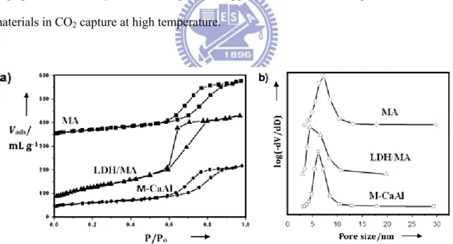
LDH/MA, and M-CaAl samples. ... 41 Figure 3. 2 (a) N2 adsorption isotherms of the MA, LDH/MA, and M-CaAl samples and (b)
the corresponding pore size distribution. ... 42 Figure 3. 3 The SEM images of (a) the synthesized M-AlOOH, (b) LDH/MA, and (c)
M-CaAl samples. ... 43 Figure 3. 4 (a), (b), (d), (e) the TEM images and (c) EDS analysis of the LDH/MA sample. . 45 Figure 3. 5 (a) TEM image of the M-CaAl sample, the qualitative element mapping for Ca
(b) and for Al (c) of the TEM image by EELS analysis, (d) the overlap image of the (b) and (c) resulting images, (e) the high resolution TEM image including its ED pattern, and (f) TEM image including nanotubes and ED pattern of the M-CaAl sample. ... 46 Figure 3. 6 (a) CO2 adsorption capacity of M-CaAl sample by absorbed at 600 oC, inset
includes the rate of CO2 sorption, (b) CO2 adsorption capacity of the sample at
various temperature (200 oC, 400 oC, 600 oC, 700 oC, 800 oC), and (c) Comparison of CO2 adsorption curve in TGA and fixed bed, where the weight
(%) calculation was divided by the total weight change of the sample. ... 52 Figure 3. 7 (a) CO2 adsorption/desorption cycles of the M-CaAl sample adsorbed at 700 oC,
(b) SEM image of the M-CaAl after 30 cycles, and (c) FTIR spectra of the M-CaAl after adsorption and desorption. ... 55 Figure 4. 1 (a) small-angle XRD patterns of calcined mesoporous materials; (b) TEM
images including the high resolution TEM image, (c) N2 adsorption isotherm
and (d) pore size distribution of calcined mesoporous Al2O3 (M-Al) ... 61
Figure 4. 2 (a) Large-angle XRD patterns and N2 adsorption isotherms including pore size
distribution of calcined mesoporous materials. ... 62 Figure 4. 3 SEM images of calcined samples (M-CaAl sample (a) and (b) including EDS (c)
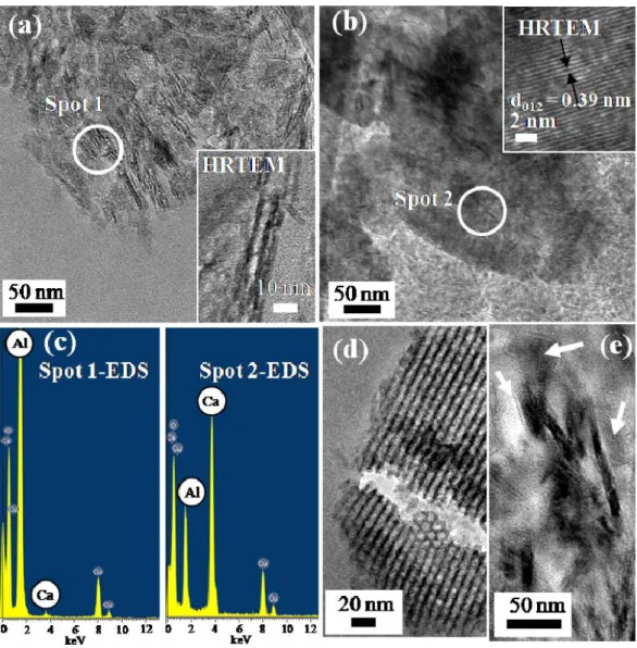
for Spot 1) and (M-2CaAl sample (d)) ... 65 Figure 4. 4 TEM images of calcined mesoporous materials (M-CaAl sample (a), (b)) and
(M-2CaAl sample (c)); (d) showing the high resolution TEM image and FT pattern of the cubic area in the image (b) ... 67 Figure 4. 5 TEM image of the M-CaAl sample, the qualitative element mapping for Al (b)
and for Ca (c) of the TEM image by EELS analysis, (d) the overlap image of the (b) and (c) resulting images. (Note: green dot indicating Ca; red dot incicating Al) ... 68
Figure 4. 6 (a) X-ray Photoelectron and (b) FTIR Spectroscopy of the M-CaAl sample prepared by microwave hydrothermal treatment for 1h and calcined at 600 oC . . 70 Figure 4. 7 (a) Large-angle XRD patterns of calcined samples (M-CaAl) with different
reactive time at 80 oC during microwave hydrothermal (MH) reaction and then calcined at 600 oC.; (b) and (c) SEM images of calcined samples (M-CaAl-MH-2h) with analyzing in two different areas. ... 71 Figure 5. 1 TEM images of the Gd2O3 nanotube of (a) along [100] and (b) along [110]. ... 80
Figure 5. 2 (a) Large-angle XRD pattern of the Gd2O3 nanotube; the indexing is based on ao
= 1.08 nm (cubic symmetry, Ia3) and (b) small-angle XRD pattern of the Gd2O3
nanotube; the indexing is based on ao = 6.54 nm (p6 mm). ... 81
Figure 5. 3 (a) TEM images, (b) high-resolution TEM (HRTEM) image, (c) ED pattern and (d) EDS of the Gd2O3 nanotube. ... 83
Figure 5. 4 (a) N2 sorption isotherms of the Gd2O3 nanotube; (b) showing the corresponding
pore size distribution and (c) TEM image of the Gd2O3 nanotube showing order
and larger pores. ... 84 Figure 5. 5 FTIR spectra of (a) the neat Gd2O3 nanotube and (b) the Gd2O3 nanotube after
IBU uptake and IBU. ... 88 Figure 5. 6 (a) IBU release profiles from the Gd2O3 nanotube under the magnetic field
switching on and off and (b) hysteresis loop analysis of the Gd2O3 nanotube. ... 89
Figure 5. 7 Cell viability of ARPE-19 cells incubated for 48 h with different concentrations (1000 µg ml-1, 500 µg ml-1, 100 µg ml-1, 50 µg ml-1, and 10 µg ml-1) of the samples. ... 91 Figure 6. 1 Large-angle XRD pattern of the mesoporous TiO2 ultrathin film ... 98
Figure 6. 2 Small-angle XRD pattern of the mesoporous TiO2 ultrathin film (a) before and
(b) after calcinations ... 99 Figure 6. 3 TEM image of the mesoporous TiO2 ultrathin film after calcinations. ... 100
Figure 6. 4 FTIR spectra of (a) the mesoporous TiO2 ultrathin film, (b) the IBU loaded
mesoporous TiO2 ultrathin film, (c) pure IBU, (d) pure VAN, and (e) the VAN
loaded mesoporous TiO2 ultrathin film. ... 102
Figure 6. 5 Mean cumulative ibuprofen release behavior from the mesoporous TiO2 ultrathin
film with different immersed concentration. ... 103 Figure 6. 6 The molecular structure of ibuprofen and vancomycin drugs (a), the illustration
of drug loading method for various molecular size (b) and those drugs delivery profile during 30 h (c) ... 106 Figure 6. 7 Microscopic images (a-c) and cell number calculation (d) of osteoblastic cell
incubated for 48 h on the different substrate (glass as control (a), TiO2 ultrathin
film for before (b) or after calcination (c)). For cell counting, the results were averaged and presented as mean ± SD, and analyzed by Student’s t-test (p value <0.05) ... 108 Figure 6. 8 (a) SEM, (b) LA-XRD and, (c) EDS analysis of the calcined mesoporous TiO2
Scheme Captions
Scheme 3. 1 Illustration of the formation mechanism of ordered mesoporous metal oxide materials. ... 48 Scheme 4. 1 The formation mechanism of mesoporous calcium aluminate nanocomposites. 73 Scheme 5. 1 The formation mechanism of Gd2O3 nanotube. ... 86
Table Captions
Table 2. 1 A comparison of high-temperature CO2 sorbents. ... 22
Table 2. 2 A comparison of low-temperature CO2 sorbents. ... 22
Table 6. 1 Composition of calcium phosphate on mesoporous TiO2 thin films soaked in SBF
Chapter 1
Introduction
Mesoporous materials usually have high surface area and large pore volume. The pore diameters are narrowly centered at 2-50 nm. Hence, novel mesoporous materials with nanostructured morphology have been developed by different synthesized routes, which include sol-gel route, microwave-assisted synthesis, co-precipitation, solid-state reaction, and hydrothermal urea reaction in our lab. One of the objectives of this thesis study is to extend this synthesized approach to develop nanostructured porous materials, and to explore some new potential applications, such as carbon dioxide capture and controlled drug delivery.
Chapter 2 presents literature review focused on the synthesis of mesoporus materials and a potential application of these materials in the carbon dioxide capture or drug delivery is also included in this chapter.
A pre-study on the sorbents for CO2 capture, in the Appendix-1, which presents a study
focused on the synthesis of the metal oxides (M-Al-O; M=Mg, Ca, and Sr). To use hydrothermal co-precipitation route, the metal oxide precursors was fabricated by the divalent metal ion and trivalent metal ion in basic solution. These metal oxides can be use as CO2 sorbent at various adsorption temperatures. Moreover, the structural characterization
and CO2 adsorption behavior of the metal oxide is clearly described in the Appendix-1.
Chapter 3 presents the studies on a novel mesoporous CaAl oxides, which was prepared by synthesizing and modifying AlOOH-supported CaAl layered double hydroxides (CaAl LDHs) in hydrothermal urea reaction. The mesoporous CaAl metal oxides exhibited ordered hexagonal mesoporous arrays or uniform nanotubes with a large surface area, narrow pore size distribution, and highly crystalline frameworks. The mesoporous metal oxides were used as a solid sorbent for high-temperature CO2 capture and displayed a
maximum CO2 capture capacity and rapid adsorption rate longer cycle life. The formation
mechanism of mesoporous metal oxides also is firstly proposed and discussed in this chapter.
Chapter 4 presents the studies on the original mesoporous calcium aluminate nanocomposites. The microwave-hydrothermal (M-H) process was used to promote the synthesis of the nanocomposites. The mesoporous nanocomposites include crystalline nanorod grown on the mesoporous structure. The formation mechanism of the nanocomposites, and its application for CO2 capture are also suggested in this study.
Chapter 5 involves the application of mesoporous Gd2O3 nanotubes with innovative
nanostructure in controlled drug delivery. This material was prepared by combining soft template and sol-gel methods. Gd2O3 nanotube exhibited weak superparamagnetic property
and was found to be able to carry and elute a model molecule, i.e. ibuprofen (IBU), in a controllable manner via an external magnetic field. The mechanism of IBU release from the nanotubes with and without the use of magnetic stimulus was proposed. And, the formation mechanism of nanostructured Gd2O3 also proposed in this chapter.
Chapter 6 deals with the application of bioactive mesoporous TiO2 thin film in
controlled drug delivery. The TiO2 film coatings with a wormhole-like architecture were
synthesized using evaporation-induced self-assembly (EISA) method. The film own ultrathin thickness and open-porous nanostructure. By taking advantage of the tortuosity of the worm-like mesoporous architecture associated with the chemistry of the TiO2 film, a
sustained drug release using ibuprofen and vancomycin as model molecules from the film was determined. Besides, adhesion behavior of osteoblast cells, together with an in vitro apaptitic formation substantiated the cytocompatibility and bioactivity of the mesoporous TiO2 films. Such combined bioactive and drug-releasing functions of the TiO2 films ensure
an improved therapeutic performance for potential applications included orthopedics, dentistry, and drug delivery.
Chapter 2
Literature Review
2-1 Mesoporous materials
2-1.1 Evolution of mesoporous materials
According to the IUPAC definition, porous materials are divided into three classes. Mesoporous materials have pore sizes between 2 and 50 nm. When pore sizes are less than 2 nm, the materials are defined as microporous. And when pore sizes are larger than 50 nm, the materials are called macroporous [1]. Generally, porous materials can be usually used as adsorbents, catalysts and carriers owing to their high surface areas and uniform pore size.
In 1992, a novel family of mesoporous silicate-based materials, the M41S, was fabricated through self-assembly and supramolecule templating mechanism, and invented by the researchers at Mobil company [2] and Toyota Research Center [3] simultaneously. The M41S materials with their ordered channel and interconnected pore systems, uniform apertures in the range of 2-10 nm diameter and surface area greater than 800 m2/g have expanded the pore size related application of zeolites and zeolite-like materials from the microporous to the mesoporous regime [4-5]. Several mesoporous structures including 2D-hexagonal MCM-41(P6mm), 3D-bicontinuous cubic MCM-48 (Ia-3d) and lamellar MCM-50 etc. have been reported in Figure 2.1 [6-8].
Figure 2. 1 Structure of ordered mesoporous materials [6-8].
2-1.2 Formation mechanism of mesoporous materials
Typical mesoporous silica material is formed by micelle-templating process, either following electrostatically driven cooperative assembly pathway or the nonionic route in the presence of surfactant as structure directing agent [9]. Figure. 2.2 shows the mechanism for the synthesis of mesoporous silica under electrostatic interaction pathway. The steps in the synthesis include:
(1) displacement of the surfactant counterions by inorganic cations forming organic- inorganic ion-pairs, which self organize into a liquid crystal-like mesophase,
(2) crosslinking of the inorganic species,
Moreover, alkyl poly(ethylene oxide) oligomeric surfactants and poly(alkylene oxide) block copolymers are the nonionic surfactant used in the nonionic route [10.]. Hydrogen bonding is a predominant driving force for pairing the inorganic and organic species in the presence of neutral nonionic surfactant [9]. Generally, cationic or nonionic surfactants are utilized as the micelle template to obtain well-ordered mesoporous materials. The massive production and relatively low cost of anionic surfactants (phosphate, sulfate, carboxylate, sulfonate, etc) has attracted researcher's focus on the synthesis of ordered mesoporous materials using anionic surfactants as templates[11.]. Yokoi et al.[12] reported the first synthesis of the anionic-templated mesoporous silica (AMS) using anionic surfactant. An organoalkoxysilane with a positively charged functional group is introduced as an additional silica source to interact with the anionic headgroup, forming the silica-micelle composite.
Figure 2. 2 Mechanism for the synthesis of mesoporous silica under basic condition in the presence of cationic surfactant[9].
2-1.3 Formation method of Mesophase
Ordered mesoporous materials in micelle-templating system can be synthesized by following the conditions and synthesis methods for different types. Generally, the mesophase can be synthesized through hydrothermal synthesis, microwave assisted hydrothermal synthesis and sol-gel process.
2-1.3.1 Sol-gel process
The sol-gel process is well-established route to synthesize porous inorganic materials with controlled microstructure, high thermal and chemical stability in the micro- and mesoporous range. Sol-gel process involves hydrolysis and condensation of respective precursor to form colloidal sol for the synthesis of these porous inorganic materials [13].
2-1.3.2 Hydrothermal synthesis
Hydrothermal crystallization is the common method used for crystallizing substances from aqueous solutions at moderate temperature and pressure. This method has been widely used for synthesis from inorganic microporous materials [14-15] to mesoporous materials [16].
2-1.3.3 Microwave assisted synthesis
Microwave assisted hydrothermal synthesis is also reported for the formation of porous material. Microwave assisted synthesis offers many distinct advantages over conventional synthesis methods. These include rapid heating to crystallization temperature, homogeneous nucleation, fast supersaturation by the rapid dissolution of precipitated gels and much shorter crystallization time [17-20]. Thus, microwave heating mode provides a better way to control the crystallinity and morphology [21].
2-1.4 Synthesis routes of mesoporous materials
According Soler-Illia and Azzaroni have recently reported literature, the four synthesized routes of mesoporous materials included precipitation, true liquid crystal templating, evaporation-induced self-assembly and casting in Figure 2.3(a)-(d) [22].
(a) Precipitation (Figure 2.3(a)): this route is the cooperative assembly of the inorganic species and the template material that occurs upon hydrolysis and condensation of the inorganic species. During the process, the mesophase with local order is formed first; and aging can cause rearrangement of that mesophase which leads to highly ordered mesostructured materials. In order to obtain highly ordered pores, it is crucial to control the inorganic hydrolysis and condensation. However, precipitation methods are straightforward and large quantities are obtained at the same time, mesoporous phases obtained from precipitation can only be processed as powders, which blocks the further application of these materials.
(b) True liquid crystal templating (TLCT) (Figure 2.3(b)): this route is developed by Attard et al. which included the formation of a liquid crystalline mesophase, infiltration of this mesophase with the mineral precursor, and the formation of the mineral walls in the aqueous regions between the micelles by inorganic condensation (oxides, sulfides) or electrodeposition (metals). This method is majorly used for producing the mesoporous metal electrodes.
(c) Evaporation-induced self-assembly (EISA) (Figure 2.3(c)): the EISA process was first designed for the preparation of mesostructured thin films (MTFs) by Brinker et al.; which is based on the solvent evaporation from dilute solutions containing inorganic precursors, templating materials and other additives, thus further forming the mesoporous materials. The evaporation of solvent will drive the self-assembly of inorganic species-surfactant micelles as presented in Figure 2.4, and further organized into ordered mesostructures. The EISA procedure has been the most
widely-used method for the preparation of mesoporous nanocomposites or other organic-inorganic nanocomposites in the forms of films, filters, fibers, powders or ordered porous structure; which can be used in continuous membrane-based separation and catalysis, protective coatings, optical films, and sensors.
(d) Casting (Figure 2.3(d)): this route is hugely different from the routes presented above; which uses the porous material act as “hard template” in the synthesis instead of uses the organic surfactants for soft templating to get the pore system. A mesoporous matrix is used as precursors for the desired phase, and then removing the exotemplate to obtain the continuously porous solid or finely divided particles. This method is extremely useful in synthesis of mesoporous carbons and low-valence transition metal oxides.
Figure 2. 3 Scheme of the four synthesized routes of mesoporous materials: (a) precipitation, (b) TLCT, (c) EISA and (d) casting [22].
Figure 2. 4 Structure evolution during mesoporous film preparation via the EISA process
2-1.5 Synthesis routes of mesoporous films
The morphologies of mesoporous materials cover powder, fiber, film, hard sphere, hollow, rod and monolith [24-26]. Besides powder, film has attracted the most attention because of their potential uses in chemical sensor, membrane separation, optical devices, electronic devices and biomatrix [5, 27-33].
Figure 2.5 presents the general method for the synthesis of mesoporous thin films. The most common methods to prepare films from a synthesis solution or precursor sol are growth from solution and solvent evaporation methods. In the growth from solution method, the synthesis solution is brought to contact with a second phase. The second phase could be solid support where the film is deposited, air or liquid (oil) where the film is self-supporting
[34]. Generally solid support submerged in the synthesis solution is subjected to
hydrothermal synthesis at required temperature and time to allow formation of membrane at the solid support interface [35]. In the solvent evaporation method, a liquid film containing silica precursor, solvent and surfactant is formed on a substrate followed by evaporation of the solvent [34]. The solvent evaporation method for ordered mesoporous films is generally conducted following three routes: (a) dip-coating [36], (b) spin-coating [37] or (c) slip-casting
[38]. Dip-coating is a method where the substrate is dipped into and withdrawn from a
precursor solution. In the spin-coating method, liquid precursor is deposited on the surface of the substrate followed by the application of centrifugal force to flow the liquid radially outward. Slip-casting is another method where the precursor solution is dropped on the substrate followed by its solidification, leaving a membrane on the substrate [34]. Slow evaporation of the solvent during dip-coating, spin-coating or slip casting induces self-assembly of the inorganic species and micelles at the solid-liquid interface, leaving a film on the surface of the substrate [10]. Generally, the removal of surfactant from the mesoporous silica materials is achieved via calcinations [39] or solvent extraction [40].
Figure 2. 5 Synthesis of mesoporous film.
2-1.6 Functionalized mesoporous materials
Functionalization with amine groups can be done through several ways: (a) impregnation, (b) post-synthesis grafting, (c) direct cocondensation and (d) anionic surfactant template method.
(a) Impregnation is one method to load high amount of amines on the mesoporous silicas [41]. Impregnation of the mesoporous silica with organosilane or polymer-containing amino group was performed by adding amine to solvent, followed by addition of the mesoporous silica. The excess solvent is evaporated to dryness [41-42]. The disadvantage exhibited by impregnation is the amines loaded tend to conglomerate [43].
(b) Post-synthesis grafting is a reaction between surface hydroxyl groups (on silanol groups) on the mesoporous silicas and the alkoxy ligands of the silane, formatting a layer of tethered amine groups on the surface of mesoporous silicas [44].
(c) Direct co-condensation of amine groups is a method where amine groups are covalently bonded into the silica matrix, unlike the surface modification of
post-synthesis grafting [45]. In the direct co-condensation method, the aminosilane, surfactant and silica precursor were mixed together and subjected to aging to allow hydrolysis and condensation of silica precursor [46]. The direct co-condensation method is simpler than the postsynthesis grafting in terms of reduction in number of synthesis steps and it also allows the uniform distribution of various functional groups without pore blocking [47-48].
(d) Anionic surfactant template route: Yokoi et al. [12] reported the synthesis of anionic-surfactant-templated mesoporous silica (AMS), based on anionic surfactants as templates. Aminosilane or quaternized aminosilane used in the study, serve as costructure-directing agent (CSDA) and functional group for CO2
adsorption at the same time. The anionic-surfactant-templated route involves condensation of the CSDA with the inorganic precursors, followed by attachment of the ammonium sites of CSDA to silicon atoms incorporated into the wall and electrostatic interaction between the ammonium sites with the anionic surfactants, producing well-ordered AMS [49].
Lim and Stein [50] prepared the vinyl-functionalized MCM-41 samples by post-synthesis grafting and direct co-condensation synthesis methods. It was found that vinyl groups were distributed uniformly in vinyl-functionalized MCM-41 via direct co-condensation method, however, non-uniformly distributed vinyl groups appeared in MCM-41 via the post-synthesis grafting.
2-2 Sorbent for CO
2capture
2-2.1 Greenhouse effect and Greenhouse gas
An idealized model of the natural greenhouse effect is shown in Figure 2.6 [51]. The Sun powers Earth’s climate, radiating energy at very short wavelengths, predominately in the visible or near-visible (e.g., ultraviolet) part of the spectrum. Roughly one-third of the solar energy that reaches the top of Earth’s atmosphere is reflected directly back to space. The remaining two-thirds is absorbed by the surface and, to a lesser extent, by the atmosphere. To balance the absorbed incoming energy, the Earth must, on average, radiate the same amount of energy back to space. Because the Earth is much colder than the Sun, it radiates at much longer wavelengths, primarily in the infrared part of the spectrum. Much of this thermal radiation emitted by the land and ocean is absorbed by the atmosphere, including clouds, and reradiated back to Earth. This is called the greenhouse effect. The glass walls in a greenhouse reduce airflow and increase the temperature of the air inside. Analogously, but through a different physical process, the Earth’s greenhouse effect warms the surface of the planet. Without the natural greenhouse effect, the average temperature at Earth’s surface would be below the freezing point of water. Thus, Earth’s natural greenhouse effect makes life as we know it possible. However, human activities, primarily the burning of fossil fuels and clearing of forests, have greatly intensified the natural greenhouse effect, causing global warming.
Greenhouse gas (GHGs) are defined as the atmospheric gases that can trap the outgoing radiation and re-radiate the radiation to the planetary surface in the thermal infrared range. This is how the greenhouse effect caused and results the temperature higher than it would be. he main GHGs are carbon dioxide, methane, nitrous oxides, halogenated compounds (mainly CFCs) and ozone, the kind of gas molecule with dipole moment which would be affected by infrared radiation and also with long life time; that takes years to leave the atmosphere and causes significantly contribution to the greenhouse effect. According to
the report of the Annual greenhouse gas index (AGGI) from National Oceanic&Atmospheric Administration (NOAA) in 2011 [52], the actual contributions of these GHGs are displayed in Figure 2.7. The growth rate of CO2 has averaged about 1.68
ppm per year over the past 31 years (1979-2010). The CO2 growth rate has increased over
this period, averaging about 1.43 ppm per year before 1995 and 1.94 ppm per year thereafter. The growth rate of methane declined from 1983 until 1999, consistent with an approach to steady state. Superimposed on this decline is significant interannual variability in growth rates. The approach to steady state may have been accelerated by the economic collapse of the former Soviet Union and decreased emissions from the fossil fuel sector. From 1999 to 2006, the CH4 burden was about constant, but since 2007, globally averaged CH4 has begun
increasing again. Causes for the recent increases are warm temperatures in the Arctic in 2007 and increased precipitation in the tropics in 2007 and 2008. Nitrous oxide continues to increase at a relatively uniform growth rate, while radiative forcing from the sum of observed CFC changes ceased increasing in about 2000 and is now declining. The latter is a response to decreased emissions related to the Montreal Protocol on substances that deplete the ozone layer.
Among the GHGs, CO2 is believed as the control knob of the greenhouse effect [53],
since the concentration of CO2 in atmosphere is much more than other GHGs. Some
physical evidences also show that CO2 is the most significant climate-relevant greenhouse
gas that induces severe climate change. The major source of CO2 is the combustion of fossil
fuels or gas by power stations leading a continuing high rate of CO2 increase. The recent
data is shown in Figure 2.8 [54]. While CO2 concentration is rising from 1970 to 2010, global
Figure 2. 6 An idealized model of the natural greenhouse effect [51].
Figure 2. 7 Global average abundances of the major, well-mixed, long-lived greenhouse gases - carbon dioxide, methane, nitrous oxide and CFCs [52].
Figure 2. 8 Comparing CO2 to global temperatures over the past century [54].
2-2.2 Carbon capture technologies [55]
Although there is not universal agreement on the cause, there is a growing consensus that global climate change is occurring, and many climate scientists believe that a major cause is the anthropogenic emission of greenhouse gases (GHGs) into the atmosphere. Due to their low cost, availability, existing reliable technology for energy production, and energy density, fossil fuels currently supply over 85% of the energy needs of the United States and a similar percentage of the energy used worldwide [56-57]. The combustion of fossil fuels produces carbon dioxide (CO2), a GHG with an increasing potential for by-product end-use in the
industrial and energy production sectors. The use of CO2 as a by-product would not only have
economic benefits but would simultaneously mitigate global climate change concerns. However, In consideration of how best to improve CO2 capture, there are three
technological pathways that can be pursued for CO2 capture from coal-derived power
generation: post-combustion capture, pre-combustion capture, and oxy-combustion, as illustrated in Figure 2.9 [55]. All three of these pathways are under investigation, some at an early stage of development.
2-2.2.1 Post-combustion capture
Post-combustion capture involves the removal of CO2 from the flue gas produced by
combustion. Existing power plants use air, which is almost four-fifths nitrogen, for combustion and generate a flue gas that is at atmospheric pressure and typically has a CO2
concentration of less than 15%. Thus, the thermodynamic driving force for CO2 capture
from flue gas is low (CO2 partial pressure is typically less than 0.15 atm), creating a
technical challenge for the development of cost effective advanced capture processes. In spite of this difficulty, post-combustion carbon capture has the greatest near-term potential for reducing GHG emissions, because it can be retrofitted to existing units that generate two-thirds of the CO2 emissions in the power sector.
2-2.2.2 Pre-combustion capture
In pre-combustion CO2 capture, the CO2 is recovered from some process stream before
the fuel is burned. To the extent that the concentration and pressure of the CO2 containing
stream can be increased, then the size and cost of the capture facilities can be reduced. This has led to efforts to develop combustion technologies that inherently produce concentrated CO2 streams or CO2 containing streams at high pressure, for which there are existing
capture processes.
2-2.2.3 Oxy-combustion
An alternative to capturing carbon from fuel gas or flue gas is to modify the combustion process so that the flue gas has a high concentration of CO2. A promising
technology for accomplishing this is oxy-combustion, in which the fuel is burned with nearly pure oxygen (greater than 95%) mixed with recycled flue gas. In the most frequently proposed version of this concept, a cryogenic air separation unit (ASU) is used to supply high purity oxygen to a PC-fired boiler. This high purity oxygen is mixed with recycled flue
gas prior to combustion or in the boiler to maintain combustion conditions similar to an air fired configuration. This is necessary because currently available materials of construction cannot withstand the high temperatures resulting from coal combustion in pure oxygen. For a new unit, it should be possible to use smaller boiler equipment due to increased efficiency. The main attraction of this process is that it produces a flue gas which is predominantly CO2
and water. The water is easily removed by condensation, and the remaining CO2 can be
purified relatively inexpensively. Conditioning of the flue gas consists of drying the CO2,
removal of O2 to prevent corrosion in the pipeline, and possibly removal of other
contaminants and diluents, such as Ar, N2, SO2, and NOx.
Figure 2. 9 The illustration of post-combustion, pre-combustion, and oxy-combustion systems [55].
The CO2 produced is captured prior to combustion, while transferring the energy
content of the fuel to hydrogen. Various pre-combustion routes for electricity production have been investigated, using a membrane reactor [58-59] or the sorption-enhanced reaction process (SERP) [60-61]. Hence, for using in a steam reforming reactor, the sorbent materials should own to the following requirements:
(a) It should be able to remove sufficient CO2 at the temperature range of 400-600 ºC
and in the pressure range of 1-40 bar.
(b) It should be able to withstand the high Psteam/PCO2 ratios at the steam reforming
conditions in a SERP reactor (> 20), where Psteam and PCO2 are the partial pressures
of respectively steam and CO2 gas.
(c) It should be mechanically and chemically stable for extended periods at these conditions.
(d) The kinetics of adsorption and desorption should be sufficiently fast.
2-2.3 High-temperature CO2 sorbents
Recently, for CO2 capture at high temperature, the attractive materials which applied to
a fuel-processing step for SERP can be divided in the following four types:
1. Metal oxides: the basic metal oxide (MgO or CaO) can react chemically with acidic CO2 to form CaCO3 at high temperature (200-600oC) [62]. Recently, aluminum oxide
is also studied since it is a weak basic material and with chemical modification by adding some other metal oxides composing stronger basicity, the CO2-uptake
capacity at high temperature can be greatly increased [63].
2. Hydrotalcites [64]: LDHs belong to a large class of anionic and basic clays, which is also known as the hydrotalcite-like compounds (HTlcs). And the derivatives of LDHs (calcined material) also show the ability as the appropriate CO2 sorbents at
[(M(II)1-xM(III)x(OH)2)]x+[An-x/n‧mH2O]x-,where M(II) is usually Mg2+, Ni2+, Zn2+,
Cu2+, M(III) is usually Al3+, Fe3+, Cr3+, and An- is CO32-, SO42-, NO3-, Cl-, OH-. The
majority of studies have focused on the most common naturally existing form of LDH, Mg-Al-CO3 (see Appendix-2). Many studies have shown that Mg-Al LDH
can adsorbs CO2 at about 400o [65]; however it cannot be applied to CO2 capture at
higher temperature, which further blocks its future application. Recently some studies were carried out by replacing the Mg2+ by Ca2+, and thus greatly raised the adsorption temperature to around 600 oC.
3. Double salts: Potassium double salts were identified as the active phase in the decomposition products of K2CO3-impregnated hydrotalcite using high-temperature
X-ray diffraction. Synthesizing double salts directly, rather than preparing them as a side product by decomposition of hydrotalcite, resulted in sorbents having higher adsorption capacity and improved kinetics compared with promoted hydrotalcites
[66].
4. Lithium metal oxides: the sorbents were discovered by Toshiba in their molten carbonate research when they added ZrO2 to the molten electrolyte. The product,
Li2ZrO3, was found to be a good CO2 sorbent, as were other lithium metal oxides [67-68]. In addition, Table 2.1 exhibits a comparison of high-temperature CO
2
Table 2. 1 A comparison of high-temperature CO2 sorbents. High Temp
(200‐700oC) Properties Sorbents Disadvantages
<200oC physical Layered double Hydroxides Less CO
2Capacity
200‐400oC Chemical MgO, MgAl‐LDO Poor cyclic life
500oC‐700oC Chemical CaO, CaAl‐LDO, LiZr
2O3 Poor cyclic life
>700oC Chemical SrO, SrAlO, modified‐LiZr
2O3 Poor cyclic life
2-2.4 Low-temperature CO2 sorbents
The conventional technologies for removal of CO2 are cryogenic distillation, amine
absorption [69-70] and absorbent liquid absorption through membrane contactor [71]. Amine absorption is the widely developed commercial technology for CO2 removal. However,
there are a number of drawbacks of using amine type liquid absorbent such as high energy consumption for solvent regeneration, equipment corrosion and flow problems caused by viscosity [72-73]. After removal of CO2 from its source such as flue gas via capture by amine
absorption, an additional step is needed to isolate and regenerate the solvent. Owing to the high cost of regeneration process [74], regenerable solid adsorbents appear to be alternative for CO2 adsorption over the conventional methods. Physical adsorbents based on carbons
and zeolites are able to reversibly adsorb large quantity of CO2 at room temperature [72].
Table 2.2 displays a comparison of low-temperature CO2 sorbents.
Table 2. 2 A comparison of low-temperature CO2 sorbents.
Low Temp. (<200oC) Properties Sorbents Disadvantages
Liquid (<120oC) Chemical Liquid amine High cost (Regeneration)
(100‐200oC) Physical Carbon, Zealite,
modified‐MOF Desorption at high Temp. (50‐120oC) Chemical Amine‐Mesoporous Material
However, these physical adsorbents have several disadvantages such as reduced CO2
adsorption capacity at high temperature, requirement of high temperature regeneration and poor tolerance to water [42]. Recently, there has been increased interest in developing mesoporous materials (molecular sieve) for adsorption of CO2 due to their high porosity to
facilitate rapid gas diffusion to and from their surface [75]. Their pores are large enough to be accessible for various functional groups. The introduction of functional groups such as amine groups to these mesoporous materials to create specific interactions with CO2 has
gained importance to overcome the disadvantages of the conventional amine absorption processes [76].
2-3 Mesoporous materials for drug delivery
In the past few years there has been an exceptional growth in research focused on drug delivery systems. This explosion has been induced by the features and possibilities that these systems offer to biomedicine, such as the possibility of several drugs to be administrated using new therapies improving efficacy and safety; the chance of delivering new complex drugs that otherwise would not be possible; the improvement of therapeutic responses with continuous drug release patterns rather than pulsatile; and the opportunity that recent advances in materials science and biotechnology offer to develop new physical and medical methods of drug delivery. Among all the new, available drug delivery technologies, mesoporous materials fulfill all the previously mentioned requirements. Mesoporous materials of various shapes, geometries, and compositions with interior and exterior surfaces decorated with organic functionalities have huge potential in a variety of bio-applications [77-79]. Their porosity and textural properties have fuelled their use as drug delivery systems and their chemical composition, similar to bio-glasses, make them good candidates to be employed in osseous regeneration technologies. The textural properties of ordered mesoporous silicas, such as high surface area and large internal volume, allow the
adsorption of drugs and biologically active species into their structures. The straight channels favor the diffusion of the adsorbed drugs in a controlled fashion, which depends on several factors, such as pore size, surface functionalization, and particle morphology, among others. The combination of both properties, compositional and textural, has triggered their use in bone regeneration technologies; these bio-ceramics can be loaded with specific drugs and then implanted in a damaged bone area for local release of the drugs. The reasons for such a high impact of these materials in the field of biotechnological research are based on their properties: (1) their high pore volume, which allows the confinement of a large amount of drug or biologically active species; (2) their large surface area, which means a high potential for drug adsorption; and (3) their well-ordered pore distribution, which favours the homogeneity and reproducibility on the drug adsorption and release stages.
2-3.1 Drug delivery of mesoporous materials
Mesoporous structures can be leading to controlled media for photonic reactions and organic syntheses [80-81]. Mesoporous materials with huge surface areas and pore volumes are appropriate media for storage of biological materials, including proteins [82]. The major step forward in ordered mesoporous materials as drug delivery systems is the possibility of employing their available channels as drug reservoirs with a novel quality: they can be opened and closed by different triggers, in the so-called stimuliresponsive release systems. Basically, drugs can be encapsulated inside the porous framework and then released when desired. The resulting polymer/drug composite materials usually exhibit slow rates of spontaneous drug release. Upon stimulation, the degradation of the polymer matrix is accelerated, and the release of drug molecules is thereby enhanced. There are several triggers that can activate the release of guest molecules, such as chemicals, temperature, pH, ultrasounds, light or even magnetism.
Lin and co-workers [83] attempted to cap the mesoporous channels of MCM-41 matrices with cadmium sulfide nanoparticles to physically block the vancomycin and adenosine triphosphate (ATP) molecules from leaching out. As release trigger agents, they used disulfide bond-reducing molecules to remove the channel caps and therefore release the loaded molecules under a chemical stimulus. Zhu and co-workers reported sonochemical synthesis of mesoporous spheres of calcium silicate hydrate constructed from nanosheets, with extremely high drug-loading capacity [84]. Temperature is a stimulus that can be employed to trigger the release of a certain drug from a delivery system. For this purpose, the employment of thermosensitive polymers, such as poly(N-isopropylacrylamide) (PNIPA), that open or close the channels is necessary to release or retain the loaded drug, depending on the surrounding temperature. This approach was used on L-3 phase silicates
[85] and MCFs using rhodamine 6G [86] and ibuprofen [87] as model drugs.
The use of pH as a release trigger in stimuli responsive release systems is based on the fact that certain tissues of the body present a pH slightly more acidic than blood or normal tissue, such as tumor or inflammatory tissues. The first time that the pH effect on the molecular release was investigated was using Al-MCM-41 matrices and fluorescein as models [88]. Yu and co-workers prepared biocompatible hollow mesoporous silica spheres with preloaded doxorubicin (DOX) for cancer therapy due to extracellular protection and pH-sensitive release [89]. A similar imaginative approach was presented by Zink and co-workers, who designed a functional MCM-41 material, where the openings were regulated by supramolecules, which were controlled by pH and competitive binding [90]. Coating the surface of SBA-15 tablets with a pH-sensitive polymer, such as hydroxypropyl methylcellulose phthalate, allows the preparation of oral release systems, and therefore it is possible to release drugs in the stomach or in the intestine (different pHs) [91]. In a similar way, it is possible to graft to the external surface of a mesoporous matrix a pH-responsive polyethyleneimine/cyclodextrin (PEI/CD) polypseudoroxotane [92]. The mesopores of
PEI-modified silica can be filled with a guest molecule (calcein) and then blocked with CD at pH 11. At pH 5.5, the calcein molecules are released by the reversible dethreading of the CDs from the PEI chain.
Ultrasound can be used as an external trigger for the pulsatile release of a certain drug. In a research work carried out by Honma and co-workers, ordered mesoporous silica was modified with poly(dimethylsiloxane) and ibuprofen was released under the stimulus of ultrasound [93]. An efficient, reversibly operated nanovalve, able to be turned on and off by redox chemistry, was developed by capping the mesopores with a pseudorotaxane [94-95]. The opening of the valve was stimulated by the addition of an external reducing agent that caused the pseudorotaxane to disassemble and the drug to be released.
As with all the stimuli mentioned above, light is an external stimulus that can cause change and, therefore, a system that responds to this external stimulus can be developed. This was achieved in MCM-41 nanoparticles modified with two azobenzene derivatives that were able to retain dye molecules and then release them upon exposure to light [96]. Besides, photocontrolled and reversible intermolecular dimerisation of coumarin derivates attached to the pore outlets of MCM-41 have been employed to uptake, store and release organic molecules [97]. Fujiwara and co-workers accomplished, for the first time, the photocontrolled reversible release of drug molecules from coumarin-modified MCM-41 [97-98]. In their work, a photoresponsive coumarin derivative was grafted on the pore outlet of Si-MCM-41. Irradiation of UV light longer than 310 nm of wavelength to this coumarin-modified MCM-41 induced the photodimerisation of coumarin to close the pore outlet with cyclobutane dimer. The irradiation to the dimerized-coumarin-modified MCM-41 with shorter wavelength UV light around 250 nm regenerates the coumarin monomer derivative by the photocleavage of cyclobutane dimer, and guest molecules, phenanthrene, included inside are released from the pore void. Additionally, other photoresponsive release systems
have used azobenzene molecules to release drugs from nanoparticles and deliver them inside cancer cells [99].
It is seen that stimuli-responsive controlled-release can be achieved by several techniques as stated above, such as light, magnetite, chemical, pH, and temperature, but not all of these techniques can be employed for drug delivery in human body. Photoinduced reversible release system under UV irradiation is also difficult to operate once the drug is inside the body. In addition, UV light can also cause potential damage to human tissue. The pH value and temperature responsive system has been shown variable applications for drug delivery and this technique will be promising due to the varying conditions of human body. Under certain conditions, magnet target will also be a good technique. The introduction of superparamagnetic iron oxide nanoparticles capping mesoporous silica nanorods allowed the materials to be attracted to specific sites of interest and release a drug under external magnetic fields [100]. The possibility of selectively targeting the desired organs or tissues inside the body is an important advance in the application of these matrices as biomedical devices. It is also possible to encapsulate magnetic nanoparticles with mesoporous silica microspheres to direct the material with an external magnetic field to release the drug to the specific target [101]. Using the same approach, it is also possible to introduce magnetic nanoparticles into the mesoporous channels of MCM matrices and hollow silica spheres by impregnation, oxidation and reduction procedures. Thus, it is possible to increase the iron content and the efficiency of the release system.
Xing et al. [102] proposed a dual-stimuli-responsive drug delivery system, with magnetic oriented target and pH-sensitive characters. The materials show highly ordered mesostructure, high pore volume, regular nanoparticle morphology (500 nm), and superior magnetic property. The pH-sensitive magnetic mesoporous silica nanoparticles (MMSNs) was served as a drug carrier, with ibuprofen (IBU) being the model drug. Yu et al. studied a facile synthesis to prepare Iron oxide/MCM-41 hybrid nanospheres with a large surface area
of 1334 m2 g-1 and a uniform diameter of 85 nm have been synthesized via a facile sol-gel route [103]. The hybird present a ferromagnetic property that ensures them a fast response to an applied magnetic field. Moreover, they are proven to be beneficial for loading an anticancer drug-doxorubicin hydrochloride (DOX), because a considerable loading content of 6.0% and a high entrapment efficiency of 90.5% have been achieved. Yang and co-worker [104] published that hydrothermal synthesized Fe3O4 microspheres have been
encapsulated with nonporous silica and a further layer of ordered mesoporous silica through a simple sol-gel process. The surface of the outer silica shell was further functionalized by the deposition of YVO4:Eu3+ phosphors, realizing a sandwich structured material with
mesoporous, magnetic and luminescent properties. The emission intensities of Eu3+ in the drug carrier system increase with the released amount of drug, thus making the drug release be easily tracked and monitored by the change of the luminescence intensity. Zhu et al. [105] developed a site-selective controlled delivery system for controlled drug release that fabricated through the in situ assembly of stimuli-responsive ordered SBA-15 and magnetic particles. In vitro testing of IBU loading and release exhibits a pronounced transition at around 32 oC, indicating a typical thermosensitive controlled release. Different from the two phase, Guo et al. [106] report a facile, gram-scale, low-cost route to prepare monodisperse superparamagnetic single-crystal magnetite NPs with mesoporous structure (MSSMN) via a very simple solvothermal method. It is also interestingly found that the size and morphology of mesoporous Fe3O4 NPs can be easily controlled and can be used as an effective drug
delivery carrier. It is found that Dox molecules could be stored in the MSSMN with an uptake amount of 40 mg g-1. The drug release rates are also suitable for drug delivery application, and most of the drug molecules incorporated could be released to solution in 12 h. In addition, Magnetic mesoporous carbonated hydroxyapatite microspheres have been fabricated hydrothermally by using CaCO3/Fe3O4 microspheres as sacrificial templates [107].
multi-functionalized microspheres have great potentials for boneimplantable drug-delivery applications. For example, the possible mechanism of the drug release profile from the ferrogel is schematically illustrated in Figure 2.10. In the beginning when there is no magnetic force (MF), the magnetic (fields) moments existing in the ferrogel are randomly oriented. The ferrogel is subjected to zero magnetization and the drug release profile displays a normal diffusion mode. While applying MF, the magnetic moments of the particles tend to align with the magnetic fields and produce a bulk magnetic moment. This induces the Fe3O4 particles within the ferrogel to aggregate together instantly, leading to a
rapid decrease in the porosity of the ferrogel, where the ferrogel was characterized as a “close” configuration. In other words, while the imposed field induces magnetic dipoles, mutual particle interactions occur if the particles are so closely packed that the local field can influence their neighbors. The particles attrct with each other when aligned in an end-to-end configuration and thus a “pearl-chain structure” was developed [108] due to the attractive forces that reduced the pore size of the ferrogel. Therefore, the drugs are restrictedly confined in the network of the ferrogel, causing a rapid and significant reduction in the diffusion of the drug through the ferrogel. While turning off the field, the pores in the membrance re-open instantly, which correspondingly results in a rapid re-filling of the drug-containing solution into the membrane, drug solution as both residual amount and later re-filled was released instantly at the moment of pore re-opening, resulting in a burst-like profile; however, the release turned back to normal diffusion profile shortly after the burst
MF OFF Pore open MF ON Pore close MF ON Pore re‐open Drug Bursting Diffusion
Figure 2. 10 Mechanism of “close configureation of the ferrogels due to the aggragation of Fe3O4 nanoparticles under “on” magnetic fields causes the porosity of the ferrogels to
decrease.
2-3.2 Bioactivity and release system of mesoporous materials
It was well-known that mesoporous materials can play a double role: bioactivity and release systems for biologically active species. In the near future, it could be possible to combine both aspects thanks to the design of novel bioceramics with the added value of delivery systems. Biodegradability and biocompatibility are the fundamental requirements that determine the possible therapeutic and surgical applications of a polymeric biomaterial. Gomez-Vega et al. [110] first investigated the bioactivity of mesoporous silica films coated on Ti6Al4V. When tested in SBF, these coatings induced apatite formation after 7 days. Giri et al. [100] also investigated the biocompatibility of magnet/MSN stimuli-responsive controlled-release system with HeLa (human cervical cancer) cells. The appearance of healthy intact nuclei and the visibility of fully grown cells by transmission suggested that the magnet/MSN systems are biocompatible with HeLa cells in vitro under the experimental conditions. Previous research found that the bioactivity of silica-based ceramic materials is strongly dependent upon the phosphorous content of the glass. Thus, Vallet-Regi [111] investigated the bioactivity of MCM-41 mesoporous material doped with phosphorous. In
the in vitro tests, the material revealed a bioactive response only after 13 days of assay. Another strategy used in order to increase the bioactivity process is the preparation of biphasic mixtures, in which one phase acts as apatite nucleation sites, accelerating the process. Andersson et al. [112] reported a degradable, hierarchically porous silica/apatite composite material for drug delivery. The composite is suitable as bone filler material, and a localised, controlled drug release from osteoconductive implant. Onida et al. [113] reported the synthesis of an ordered mesophase within a macroporous glass-ceramic, in order to combine the bioactivity of the latter with the release properties of ordered mesoporous systems. It is demonstrated that mesoporous silicas, MCM-41, MCM-48 and SBA-15, are bioactive materials if used as substrate for drug delivery system. However, the biocompatibility is not so strong. Modification with phosphorous or active component such as apatite will significantly improve their biocompatibility.
In the past few years, the biomedical research area has shown a growing interest in ordered mesoporous materials because of their promising applicability in the context of drug delivery and tissue engineering, especially in bone tissue regeneration. The combination of both properties, compositional and textural, has triggered their use in bone regeneration technologies [114]; these bioceramics can be loaded with specific drugs and then implanted in a damaged bone area for local release of the drugs. The main role of bone formation must be played by specific living cells, which present dimensions of the order of hundreds of mm. Taking into account that mesoporous channel diameters range between 2 and 50 nm, it is obvious that cells need larger pores to attach into them. Consequently, the challenge then is to obtain scaffolds combining macroporosity for bone oxygenation and vascularisation, and mesoporosity for applications where drugs or biologically active molecules are loaded and then released.
Vallet-Regı ́and co-workers [115] synthesized mesoporous silica-zirconia mixed oxides with tunable acidity via spraydrying process as controlled release vectors of isphosphonates
for bone implant technologies. Gomez-Vega and co-worker [116] prepared mesoporous silica coatings using self-assembling organicyinorganic sol-gel systems. The resulting mesoporous silica coatings were able to induce apatite formation after 1 week of immersion in a simulated body fluid in physiological conditions, which is a sound indication of a bioactive behavior when tested in vivo. These results indicate that the coatings prepared by the methodology described in this work may be valid candidates to be used on implants. Perez et al. [117] reported a new type of implantable drug eluting device, consisting of a bed of mesoporous microparticles packed inside a reservoir with a porous wall. This provides two sets of variables for drug release control that can be tailored independently. Ehlert et al.
[118] reported the material where a sulfonate-functionalized mesoporous silica layer is loaded
with ciprofloxacin and then coated by an organosiloxane layer derived from bis(trimethoxysilyl)hexane showed the best results with regard to antibacterial efficacy and will further be tested in animal experiments. Li et al. [119] reported the mesoporous amorphous calcium silicate (MACS) using mesoporous silica SBA-15 as both the template and silicon source, and Ca(NO3)2 as the calcium source. In vitro bioactivity studies of the
MACS were carried out by soaking it in simulated body fluid (SBF) solutions for 4 h up to 5 days. The MACS did develop a carbonatecontaining hydroxyapatite (HCA) layer on the surface after being immersed in SBF for 4 h with near-spherical agglomerated hydroxyapatite (HA) nanoparticles.
Common coating materials suggested for improving bioactive properties of implant materials include crystalline titanium dioxide and calcium phosphate based coatings or surfaces. However, suggested methods for improved bioactivity cannot completely eliminate the risk of obtaining infections at the implant surface. Many publications are concentrated with fabricating different roughness and specific topography of biomaterials’ surfaces aimed to improve cytocompatibility of the surface. To improve the bioactivity, many surface modifying techniques, such as sol-gel coating [120], plasma spraying [121] and
![Figure 2. 2 Mechanism for the synthesis of mesoporous silica under basic condition in the presence of cationic surfactant [9]](https://thumb-ap.123doks.com/thumbv2/9libinfo/8049837.162345/22.892.158.757.456.1014/figure-mechanism-synthesis-mesoporous-condition-presence-cationic-surfactant.webp)
![Figure 2. 3 Scheme of the four synthesized routes of mesoporous materials: (a) precipitation, (b) TLCT, (c) EISA and (d) casting [22]](https://thumb-ap.123doks.com/thumbv2/9libinfo/8049837.162345/26.892.293.667.122.616/figure-scheme-synthesized-routes-mesoporous-materials-precipitation-casting.webp)
![Figure 2. 7 Global average abundances of the major, well-mixed, long-lived greenhouse gases - carbon dioxide, methane, nitrous oxide and CFCs [52]](https://thumb-ap.123doks.com/thumbv2/9libinfo/8049837.162345/32.892.215.707.494.927/figure-global-average-abundances-greenhouse-dioxide-methane-nitrous.webp)
![Figure 2. 8 Comparing CO 2 to global temperatures over the past century [54] .](https://thumb-ap.123doks.com/thumbv2/9libinfo/8049837.162345/33.892.276.646.102.400/figure-comparing-global-temperatures-past-century.webp)
![Figure 2. 9 The illustration of post-combustion, pre-combustion, and oxy-combustion systems [55]](https://thumb-ap.123doks.com/thumbv2/9libinfo/8049837.162345/35.892.182.746.463.987/figure-illustration-post-combustion-pre-combustion-combustion-systems.webp)
![Figure 3. 1 (a) small-angle XRD patterns [172] , (b) large-angle XRD patterns of the MA, LDH/MA, and M-CaAl samples](https://thumb-ap.123doks.com/thumbv2/9libinfo/8049837.162345/57.892.292.628.111.802/figure-small-angle-patterns-large-angle-patterns-samples.webp)