Self-correction two-machine equivalent model for
stability control of
FACT
system using real-time
phasor measurements
C.-S. Yu and C.-W. LiuAbstract: A self-correction two-machine equivalent model for the stability control of a flexible AC transmission (FACT)-based transmission system is developed. Shaping of the self-correction two- machine equivalent model uses only the real-time phasor sigi~?ls available from the synchronous phasor measurement units (PMUs). The errors between the proposed model and practical power system are corrected by real-time measurements. The adaptive and robust behaviours both get involved in this modcl. In addition, linearity approximation is not used in its development. The proposed model is appropriate for transient stability control. Via the self-correction two-machine equivalent model, this work successfully applies the direct feedback linearisation (DFL) technique to a inultimachine interconnected power system for transient stability control. The parameters and model uncertainties are also considered in the proposed DFL controller. This appr-oach is then successfully applied to a three-area six-machine test system that installed two thyristor-controlled switch capacitors (TCSCs) controllers. Simulation results indicate that the proposed model and DFL controller are effective and robust in stabilising the transient swings between interconnected systems under various system conditions and the occurrence of severe faults.
1 Introduction
Recently, the steadily growing demand for electric power has required the construction of new power plants or transmission lines. However, due to environmental and economic limitations. transmission systems are not easily constructed. Instead, more power must always be trans- mitted over long distances. This transmission always introduces new problems
to
power systems, such as power transfel- limitation or increased system stress. An econoniic- ally attractive approach for overcoming these problems is to install series compensation FACT devices on the long distance tie-line. The most popular FACT [ I ] devices for series compensation are the switch capacitor (SC) and the thyristor-controlled switch capacitor (TCSC). However, new installations of FACT devices also introduces new problems to power systems, such as new real-time control problems for the fast response of FACT devices or the new interarea transient stability control problem [2,31.
Previous work [2, 31 has successfully applied the switch capacitors to an interconnected multimachinc power system for transient stability control. However, both studies only focus on the open-loop type ’bang-bang’ control, which requires off-line planning of the switching policy. To achieve interarea transient stability control, in [2], the authors propose a two-machine equivalent model based on centre of inertia (COI) variables. Vilr the equivalent model of [2], the interconnected power system is reduced to a second-order equivalent system. That study adopted the model for robust
bang-bang control. However. the internal voltage variables used in this model are not practical variables. Instead, they need off-line simulations. In addition, when the system has some uncertain dynamics. thc control strategy will become invalid. Thus, when real-time adaptive performance or uncertain system dynamics are considered. the control strategies proposed in [2, 31 are inappropriate. To achieve real-time adaptive control, differential geometry-based direct feedback linearisation (DFL) [4] has been proved to be an effective technique for solving the transient stability problem. In [j], the DFL technique is successfully applied to a multimachine power system. However, only thc classical two-order generator model is considered and linearisalion only applies to the individual machine. Other investigators [6, 71 successfully apply the DFL technique to a third-order machine model with an additional voltage regulation. However, those investigations only focus on the single machine infinite bus (SMIB) system. The DFL technique has not actually been successfully applied to interarea transient stability control. In addition, in considering the fourth or higher-order generator model [8], the closed form of the DFL controller has also not been successfully developed. The main problems of the DFL technique are the necessity Tor a precise system model and a closed form to cancel the nonlinear tenns in the system model. The precise model cannot be obtained in many power systems. To overcome the problems mentioned above. this work presents a self-correction two-machine equivalent model for FACT systems. The characteristics of the proposed equivalent model are as follows:
(i) The self-correction two-machine equivalent model is corrected using only real-time phasor measurements, which are available from global positioning system based phasor measurement units (PMUs) (91.
(ii) Tie-line parameters (such as line impedance, terminal bus voltage magnitude and bus voltage phase) are used as variables in the proposed equivalent model. The proposed model is appropriate to thc FACT controller design. (iii) Linearity is not used in developing the proposed equivalent model. The proposed equivalent model is appropriate to the nonlinear controller design.
(iv) The form of the equivalent model is the second-order state equations and is similar to the classical generator model. Via the proposed equivalent model, the analysis for multimachine system becomes easier and the closed form of DFL is easily obtained.
(v) Although the proposed equivalent model is not precise, it is corrected by real-time measurements. Robust and adaptive characteristics are both involved in the model. Thus, the application of DFL technique will become more practical via the model.
2 Self-correction two-machine equivalent model In this Section, a self-correction two-machine equivalent model is developed. This model is cspscially appropriate to the FACT systems. To develop the proposed model, we consider an interconnected multimachiiie power system, which includes n generators and n + m buses. Bus I is the slack bus, bus 2 to bus n are PV buses and bus n + 1 to bus
n+m are PQ buses. The models of generators, transmission lines
and
loads used in the simulated power system are expressed as follows:i = l > . . : n Mi&; = Pmi - Diu;
-
P , i = I , ..: n~ i = ( E , , ( t ) - E b i + / ~ ~ ( x d - x ~ ; ) ) / T ~ ~ i = I , . . . > n
P d = ( - E ' . - I - v, q r ( x q i - x ~ , ) ) / ~ ~ o i = l , . . . : n Pe; =E&,
+
ELJg+
(
xd';
- x;,)
. Iglq; i = 1 : . . . ~ 11Vd = E:, - G j I q Z
V,,i = E;;
+
&Id,V, = V,i t j V , i = I ~ . . . ~ n i = I ~ . . .
,
II i = I =2
KF(gocos(Bi - 0,)+
bijsin(0, -8,));
= I ,. . . ,
n + m J=IQP =
f:
K<(gosin(8, - 8,) - b,,cos(~; - 0,))i j= I= 1:
. . . ,
n + m ( 1 )where M; inertia of each generator i,
P,,,;>
D;
the desired mechanical power input and damping of generator i,pf
the constant real power injection of bus i,@
the constant reactive power injection of bus i, E&, the transient EMF in the d-axis of the generator i, Ebi the transient EMF in the y-axis of the generator i, Tio &xis transient short circuit time constant of the generator i, .I&, xg, transient and synchronous d-axis reactance of the generator i, xi;, .xPtransient and synchronous y-axis reactance of the generator
I, Pet the electrical air-gap power of the generator i, 6 , w ; the power angle and angle speed of the generator i, V;, 0;
390
the voltage magnitude and angle of bus i, gs. bo the conductance and susceptnnce of transmission line between bus i and bus j .
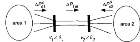
The interconnected power system is divided into two groups with respect to the tie-line depicted in Fig. I
Fig. 1 Tiw-orwi inrerconnecred g ~ r ~ e n i with weuk tie-hc Notably. the division of this system only depends on the l o d o n of the tie-line. To simplify the description of the variables used in the proposed model_ the concepts of centre of inertia (COl) are borrowed from [IO], and the COI variables of the two groups are defined as follows:
for group 1
for group
2
(2) where indices ;= I . . . ? k refer to the gtierators in group I.
and indices i = k + 1 ...: n refer to the generators in group 2 . The real power deviation output from generator i is written as P,,, - Diu; - P,;.
The summation of the total real power deviation output from the generators in each group are represented as follows:
M;C;
=1
(P,,?, - Djw, -re;)
(3)w h e r e i = l ..., k f o r g r o u p I, a t i d i = k + l ... n forgroup2. For simplification, the right-hand side of ( 3 ) is defined as
Ae,,
where;= 1 for group 1. a n d j = 2 for group 2. Using the COI variables defined in(2),
(3) is rewritten in the fomi of COI variables as follows:4:
,
= w !,
where i = 1 for group 1. and i = 2 for group 2 2.
I
Basic form of the proposed modelTo develop the self-correction two-machinc equivelcnt model, three assumptions are temporarily used to develop the basic form of this model. However, these assumptions will be removed to get the final equivalent model. The three assumptions are as follows:
(i) The transmission line is lossless.
(ii) The load model is assumed to be a constant power model.
(iii) The local mode oscillation in each group is well damped and can be ignored in each group.
Since the real power deviation dissipates on the transmission line and the real power deviation swing I E E Proc-Ccner. Trunsrii. D~.$m/>., V d 149. No. 4, Ji$ XNI2
between the generators and load in each group are all temporarily ignored. the summation of total real power deviation outpnt from generators in group 1 is exactly equal to the real power deviation transmitted on the tie-line. The real power deviation transmitted on the tic-line is also exactly equal to the summation of total real power deviation that flows into the generators i n group 2. The directions of real power deviation are all depicted in Fig. 1. The basic form of real power deviation that Rows on the tie-line is expressed as follows:
( 5 )
6 6
AClic(baric) Pvc - sm(0l ~ &)
X L
where (V,,&)and (V&are the voltage phasors of the tie- line terminal buses of the tie-line, rcspectively. x,. denotes the tie-line impedance. and Pswc denotes the desired real- power transmitted betwcen thc interconnected systems in a steady state (i.e., the steady-state load Row solution of the real power flow on the tie-line). The relationships between these real power deviations in Fig. 1 are written as follows:
(6)
~P:I =APiic(biric)
4 : 2 = - Aptie(b3sic)
Using the above assumptions, for group 1, (4) is rewritten as follows:
6;
=m;
The dynamic response of COI variables between two groups are represented by the following rclationships
. .
a;
- 8; = w ; - m;1 I ( 8 )
&J; - io; =
M;
- A P ~s(hiiiic)+
RAPtie(b;ac) For simplification, two new CO1 variables are defined as follows:6col = S; - s:wCol = W ; ~ 0,; (9)
Eqn. (8) is rewritten as follows: 6COl =
where
I l
+-
l_ = -
Mr
M;
!!4;Up to now, the basic fonn of the two-machine equivalent model has been successfully developed in ( 5 ) and (lo). 2.2 Adding self-correction terms to remove three assumptions
In the previous discussion, three assumptions are used for developing the basic from of the proposed model. In considering the practical system. three assumptions are not reasonable, especially assumption (i). In the following discussion, these assumptions are analysed and quantified. Then, the self-correction two-machine cquivalent model is developed to remove thcse three assumptions.
These assumptions mainly ignore the nnmodelled real power deviations that generate in one group and do not flow to the tie-line. When the states of system reach their equilibrium points, all of the unniodelled real power deviations generated from tbesc assumptions will vanish, ICE P w . ~ G ~ w c r . liii~nai W m d . VoL 149, No. 4. l l i l j . ZUU2
and the models of ( 5 ) and ( I 0) will become valid. Therefore, three assumptions could he quantified as a mismatch term
AP,, and added to (7) as the following self-correction form:
sin(@, - 82)
where the mistnatcb term AP,, denotes the unmodclled real power deviation generated from the three assumptions. When the states of system ]-each their equilibrium points, the mismatch term
de,,
will vanish and (12) is equal to (7).When the states of the system are far from their eq&briiiin points. the CO1 acceleration speed calculated from ( 5 ) and (IO) (we call it WcOlz) will contain some errors and not be eqilal to the CO1 acceleration speed calculated from the measurements of the practical system (we call it Wcoii). Thus, the difference between the above two COI acceleration speed signals is used to account for the mismatch tenn AP,, as follows:
(13)
AP,,, =iMf(Wco,t 7 WCOIZ)
=iw"W r COII - A P t i c ( b m )
Then. (IO) is written in the following self-correction fonn: 6col =wcni
WCOI = - A Ptic(rli-correcuun)
Eqn. (12t(14) are the self-correction two-machine equiva- lent model. The basic form of real power deviation AP,,ecbdsic) is used to compute the tnisinatch tenn AP,,,.
Using the proposed model in (12k(14), the intercon- nected power system is simplified to a self-correction two- machine equivalent model. The resultant model retains the parameters of transmission line where the FACT devices are installed. and the other portions of the power system are all reduced. Thus, the proposed model is very suitable for the longitude power system that has a long weak tic. Via the proposed model, the transient stability control design can he achieved by appropriatcly tuning the parameters in (12). Using the new developed FACT devices, most of the parameters i n (12) can be easily controlled. For example, the transmission line impedance x,. is tuned by TCSCs (thyristor-controllcd switch capacitors), bus voltages V I and
V, are tuned by SVC (static VAr compensator [SI) and the phase difference HI& between two terminal buses is tuned by PS (phase shifter [Ill). In addition, the inverter-based FACT devices, such as UPFC
[XI
or SPFC [I I], are also suitable for the simultaneous control of the above three parameters.We adopt the TCSC to regulate the transmission lines impedance for interarea transient stability control as an example. After the TCSC is installed on the tie-line, the transmission line impedance .xL in (12) is replaced by
s,+s,,, where
.\-<,<,
denotes the equivalent impedance of the TCSC device. If the voltage phasors VI and V, are measured just on two sides of the TCSC device, the transmission line impedancex,.
will equal zero and (12) is rewritten a s follows:1 (14)
M T
sin(0, ~ 8 2 )
Via the proposed self-correction two-machine equivalent model, COI acceleration speed is easily controlled by properly tuning of APtl~(*-lf~cuncc,ion). Fig. 2 depicts the
area 1 area 2
, .
...
global me?sUfementS iOCai global measurements:
l i
I
I
I
-1
I
Fig. 2 Self-mrrecrion ~tvo-nii~l~ii~e eqztiwilenr t i ~ o ~ l d block
ili&yuin
resultant structure of the self-correction two-machine equivalent model-based TCSC controller.
3
Practical issues3.
I
Multi-area power systemIn the previous Section, for ease of description, the two-area interconnected system is used to develop the selfcorrection two-machine equivalent model. The two-groups division is equivalent to the coherency division [8] of the two-area system. When the system is not two-area but n-area (n>Z),
the system states are split into IZ coherency areas. Then, in developing the self-correction two-machine equivalent model, the mitlti the area power system is still divided into two groups with respect to the considered transmission lines in the proposed model. The self-correction two-machine equivalent model can be easily applied to any practical power system that can be split into two groups with respect to the considered lines.
3.2
Feedback signals synthesisIn the self-correction two-machine equivalent model, the CO1 power angle and COI speed signal are borrowed as the aggregate state variables. However, as in [2, 31, the real COI signals are never easily measured. To overcome the measurement problem, this Subsection adopts the output feedback technique to measure the phasor on some specified buses to mimic the dynamic of COI variables. Once the COI power angle is computed via the bus voltage, the COX speed signal can be easily represented using the differential value of the COI power angle.
Optimal placement of PMUs based on coherency analysis is developed in [12]. This work follows the manners in [I21 and extends them to a COI variables-based PMU placement strategy for the self-correction two-machine 392
equivalent model. This work attempts to find a bus whose voltage angle is most sensitive to the dynamic of the considered COI power angles. That voltage angle must also he the least sensitive to the dynamic of other COI power angles. The power system model
is
hCariSed around its nominal operating point, and the linearised state equations are written as follows:x = A x
+
BL! (16)y =
cx
(17)where I denotes the generator power angles used for
calculating CO1 variables, y denotes the bus voltage angles measured by PMUs. and u denotes the command generated from the TCSC controller. Matrices A , B and C are the
constant matrices evaluated at the nominal operating point, respectively. The relationship between the CO1 variables and bus voltage angles is expressed as follows:
Xcoi =
Gx
(18)where thc nonzero entries of G are the ratios of inertias. For a CO1 power angle of area i, the criteria to find the appropiiate PMUs bus are listed as follows:
(i) The PMU bus must contain the most dynarmc information of
A&
(ii) The PMU bus must contain the least dynamic infomiation of other COI power angles.
To select the appropriate PMU bus, a m x r selective
matrix
S
is defined, where m is the amount of output variables and r is the amount of coherency areas. Each entry of matrix S is defined as follows:sij
=(ci,
C j . )
C, =the ith row of matrix C (19)
Gj =the j t h row of matrix G
Each column of matrix S is further normalised to fonn the nonnalized selective matrix Sn as follows:
SniJ = S,/(two norms of the j t h column of matrix S) (20)
Thc selection procedures for the PMU bus are written as follows.
(i) Define a vector H t K ' for b& (ii)
(iii) The PMU are installed at bus,j, when H . - max
Hk.
H j = SnJi when Sn .. - max Snin
" - I S M Hi = 0 otherwise
-
I<kc"?Once the PMU bus has been determined, the dynamic hehaviour of the CO1 power angle for group i is substituted with the corresponding PMU bus voltage angle 0; (where bus jt group i). To simplify the representations, 0; E 0: is
defined to signify bus volvage angle that represents the COI power angle dynamic behavior of group i. The COI power angle
6col
between two groups is approximated byz
012 = 0; ~ B;, and the dynamic behaviour of theCOI power angle between two groups can be approximated via the real-time bus voltage phasors.
4 Self-correction two-machine equivalent model-based DFL controller
4.1
Control theory developmentIn this work. the direct feedback linearisation (DFL) technique is adopted as the control law. When the DFL technique is applied, the major problem is to find a command such that the nonlincar term of system is replaced with a specific linear system. However, when multimachine power system is considered, the DFL command cannot be found easily. Also? when the fourth- or higher-order generator model is considered, the DFL command cannot ,- even he found in a single machine infinite bus (SMIB) system. Furthermore, when the system includes some uncertainties, the nonlinear term cannot he completely replaced and the DFL technique will become invalid. Thus, practical application of DFL still presents problems.
As mentioned above, the multimachiiie power system has been successfully expressed as a nonlinear two-order system via the self-correction two-machine equivalent model. Thus, the multimachine power system DFL problem is changed to the second-order SMIB DFL problem. The main problem is changed to find a controller command such that the closed loop bchaviour of the second-order self-correction reduced model is equal to a specified linear system. For the resulting second-order model, the DFL technique is easily applied as the following procedures:
First, the nonlinear terms in (14) are replaced with a command c(t) and rewritten as follows:
k 0 l =WoI
Oco1 =u(t) (21)
Via the DFL technique, the linear control technique is adopted to design the command E ( / ) as I'ollows:
U ( t ) = -KUJcoi (23) Substituting (23) into (21). (21) is rewritten as follows:
Substituting (23) into (22). TCSC equivalent impedance is designed as follows:
-
U =.rq
= r{
( 9
h
sin f l 1 2 ) / [ ( ~ ,+
df,,)+
M r K w o i l }( 2 5 )
All signals involved in (25) are available from the PMUs, and this controller can be easily applied to real-time applications. Once the parameter K is determined, all parameters in the state (24) are known and the hehaviour of the nonlinear system (14) is equivalent to a linear system Via the linear control law, the relation between the settling time t., and the parameter K is written as follows:
t.< = 4/K ( 2 6 )
where the steady-state error of wcoI is 2%. The designing of parameter K is independent of various operating points,
and the resulting system is a globally stable system. When only a two-machine power system is considered, only one generator is contained in each group of Fig. 1.
Moreover, if the real power deviation APtje(uif-comt,onj in (22) is replaced by AP,,,(,,,,j, the controller command of IEE Proc.-Geue,~. Trmm8. IXwih.. Vol 149, N o 4. h r l v 2002
(25) is similar to the results of the conventional DFL techniquc. Thus, the conventional DFL technique is only the special case of the proposed cquivalent model-based DFL technique.
4.2
Robustness discussionAs mentioned in the previous Subscction, the uncertainty dynamics included in the system will make the application of the convention1 DFL technique very difficult. Even in the simple SMIB case, the imprecise model also makes it impossible for the conventional DFL technique to com- 'pletely remove the nonlinear term of the system. Then, the conventional DFL-controlled system will retain some uncontrolled terms, and the dynamic performance of the system will not precisely follow the performance of specified linear system. If the uncontrolled terms are sufficiently large, the uncontrolled oscillations will cause the conven- tional DFL controlled system to become unstable. Thus, the validity of the system model is vital in designing the conventional DFL controller, and the robustness is very difficult to achieve by the conventional DFL technique.
Avoiding the necessity of .the precise model for the conventional DFL technique, the self-correction two- machine equivalent model-based DFL controller does not need the precise model. Instead, the self-correction reduced- order model is corrected by real-time measurements from PMU. Since the model errors are corrected on-line, the dynamic response of the resulting system can follow the dynamic response of the specific linear system. Thus, robustness can be easily achieved via the self-correction two-machine equivalent model.
5 Simulation results
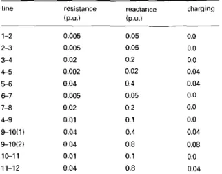
This Section demonstrates the feasibility of the proposed self-correction two-machine equivalent model and the proposed DFL controller. The eqnivalent model is only adopted for controller design purposes. The time-domain responses of all the signals are computed using the model described in (I). The simulation system considered is a three-area, six-machine power system with two TCSC devices, TCSCl and TCSCZ, as shown in Fig. 3. Table I summarises the transmission system data. All generators are identical and are modelled with a fourth order state cquation. The parameters of generation and load are in [13]. No power system stahilisers (PSS) are installed 011 generators for damping the local mode oscillation in the
-
4
area 3
Table 1: Line parameters of the test system
line resistance reactance charging
1P.U.) (P.U.) 1-2 0.005 0.05 0.0 2-3 0.005 0.05 0.0 2-4 0.02 0.2 0.0 45 0.002 0.02 0.04 56 0.04 0.4 0.04 6 7 0.005 0.05 0.0 7-8 0.02 0.2 0.0 6 9 0.01 0.1 0.0 9-1011) 0.04 0.4 0.04 9-1012) 0.04 0.8 0.08 1&11 0.01 0.1 0.0 11-12 0.04 0.8 0.04
group. The excitcr model block diagram and exciter data are the same as in [13]. Thc constant impedance load model is adopted rather than the constant PQ load model to demonstrate the robustness of the proposed equivalent model. The output ranges of TCSCl and TCSC2 are
.i-Y
= 0.2 pu and.Y:Y
= -0.5 pu. Meanwhile, the equili- brium operating points of two TCSCs arc equal 10 X,, = -0.4pu. Notably. thc TCSC devices are only used to demonstrate the feasibility of the proposed model. Via the proposed model, other FACT devices also can he easily applied to this system. Fig. 3 cncloses three areas of the system with dashed lines.5.1
Test conditionA three-phase h u l t occurs on the tic-line without TCSC installed between Bus 9 and Bus IO and near Bus 9 at
I = 0.167s. The fault is cleared after six cycles and the faulted transmission line is disconnected.
The COI angles of all three areas arc defined as: (i) CO1 angle of area 1 = (6, +&)/2;
(ii) COI anglc of area 2 = (6, + &)/2;
(iii) COI angle of area 3 = ( 6 ,
+
6,)/2;where 6, is defined as the power angle of generator i. To analyse the three-areas system, the following four variables are defined.
6coll = (COI angle of area 1 +COI angle of area 2)/2-C01 angle of' area 3
Ocorz = (COI angle of area 2
+
COI angle of area 3)/2- COI angle of area II/M& l/(wl+w;)+l/Mi I/&=
l/(ll.rz+M;)+I/M;
where Mi are the same as defined in (2). Thus, the system is decouplcd and changed into two independent reduced order systems corresponding to the tie-lines.
5.2
Reduced order systemI
5.3
Reduced order system2
k O l ? =("CoIz
wherc AP,f, is the real power deviation flow on tic-line I between bus 9 and bus
IO,
and AP,:c is the real power deviation Row on tie-line 2 between bus 5 and bus 6. Both of the real power deviations are a s defined in (15).5.3.1
Case1:
The effectiveness test of the self- correction two-machine equivalent model: The settling times of TCSCs controllers are both ~ v e n as 0.8 s. Using the above design procedures. the controller gains K of two TCSCs are both designed as 5 ( K = 4/1,=4/0.8). The PMUs are installed at bus 2. 8 and 12 to measure the COI variables of areas 1. 2 and 3; respectively. Meanwhile; the PMUs are also installed at buses 9 and I O to measure theAP;,, and installed at bus 5 and 6 to measure the AP$ Figs. 4 and 5 present the simulation results of the speed signal of W C O I ~ and W C O ~ ~ , respectively. For comparison, the solid lines denote the case whcn the controller is working, and the dashed lines denote the case when the controller is not working. Notably. the system performance of solid lincs follows the settling time specifications.
5.3.2
Case2:
The robustness test of varioussystem parameters: The following simulations discuss
2.5
,
Ithe robustness of the proposed model and controllcr. System uncertainties are considered as two parameters k, and cPQ. and the two parameters are dcfined as follows. (i) k,.= RIA’, the transmission line resistance to inductance ratio (in the normal case. k,=O.I).
(ii)
{
cPQ = 0 : Load modelled is constant impedance model (cPQ = 0 is considered as the nominal case in the tcst case) Notably, the unmodelled terms between the self-correction two-machine equivalent model and the practical system vanished when k,=O and cPQ= 1. The robustness tests includek,-0.0.05,O.l.O.I5,0.2andcPQ=O, ILThebasic fonn and self-corrcction form of the proposed equivalent model are used for comparison. Figs. 6 and 7 show the simulation results of system responses uio the basic form and self-correction foim, respectively. In Fig. 6, the basic form of (IO) is used to design the controller command. The siinulation results indicate that the system performance does not follow the settling tilnc specification. when the various uncertainties are considered. Fig. 7 applies the self-correc- tion fonn of (14). The simulation results show that the system perfoimance is not affected by various uncertrlinries, and the system response will always follow the specified settings in Fig. 7. In considering Fig. 6_ the unmodelled tenns will prwide the majority effects when the interareacPQ = I ~ Load inodelled is constant PQ model
2.5 2.0 r 1.5
e
% n2
1.08
0.5 0 .. . . . .. . . .. .. . .. . . .. . . .. 2.5 2.03
1.5 ! ! d P 1.0E
3
0.5 0 -0.5transient is nearly damped out. Since the unmodeled terms are not shown in the basic form of (IO) the system will become unstable. Notably. in Fig. 7. the responses of cPQ= 1 and k,.=O will follow the specified setting since the
unmodelled teims alniost disappear here.
5.3.3 Case
3:
The robustness testof
various controller pXi”terS: The following simulations use ,,different settling times r,,=0.2. 0.4> 0.8, 1.4s, and the corresponding controller commandsK =
20. IO. 5. 2.56, respectively. Figs. 8 and 9 illustrate the system response of different settling time using the proposed DFL controller. In Fig. 8, the basic form of (IO) is used to design the controller command. The system responses do not follow their specified settlings, and are influenced by the system uncertainties (k?-
0. I I cPQ = 0). In Fig. 9. the self-correc-tion foim of (14) is used to design the controller command. The system responses of different settling times all follow their specified settings, confirming the accuracy of the proposed model and controller. In considering Fig. 8, these uncertainties provide uncontrolled oscillation in the system response. Also, errors induced from the system uncertainties will increase when the settling time is large (Kis small). since the unmodelled terms are relatively larger than the interarea transient when K is small. However, when given a Small setting time (and thus K is large). the system response will
correction 2.5 2.0 $ 1.5 E m 1.0
%
E
$
0.5-
0 -0.5 0 0.2 0.4 0.6 0.8 1 1.2 1.4 Time, 5 lault clearclosely follow the specified setting, since the considered interarea transient is relatively karger than the unmodelled temis.
As mentioned in Section 4. when the basic form of (IO) is used to design the controller, the resultant response is similar to the response of conventional DFL. When the system uncertainties are considered, the controller designed via (IO) is invalid. All of the simulation results demonstrate that the proposed self-correction two-machine equivalent model and the proposed DFL controller are effective and robust under various system parameters and controller command.
6 Conclusion
This work has successfi~lly proposed the self-correction two- machine equivalent model for the stability control of FACT systems. The proposed model needs only the real-time niedsureinents from PMUs and does not need the iinedrised approximation. In considering the uncertainties of the system parameters, the proposed model allows most of the uncertainties. and the proposed equivalent model can still follow the dynamics of practical systems. Thus. the proposed model is adaptive, robust and appropriate to nonlinear controller design. Via the self-correction two- machine equivalent model, the DFL technique is success- fully applied to multimachine power systems for stability control. Simulation results demonstrate that the self- correction two-machine equivalent model and the proposed DFL controller are effective and robust for stability control
of
interconnected systems under various system parameters and various controller commands. Although this work only discusses the TCSC installed system and the DFL technology. the proposed equivalent model can be easily extended to the other FACT devices and the other nonlinear control strategies.7 Acknowledgments
The authors thank the National Science Council of the Republic of China for financially supporting this research under grant NSC 88-22 13-E-002-070.
8 I 2 3 4 5 6 7 8 9 I O II I2 13 References
HINGORANI. N.G.: 'Flexible AC transmission'. IEEE Spmrrrrrr,
1993. pp. 40-45
KOSTEREVE. D.N., and KOLODLIEJ. W.J.: 'Lking-bmg senn
c;tp;rilor iransient stabilily contraf. IEEE. 7 h ~ x Powr. Sy.sl.. 1995. CI.IANG, J.. and CHOW, J.H.: 'Timc-optimitl conti~oI of power systems requiring multiple switching of series oipaciori'. IEEE i%m.,
1 ' 0 ~ ~ S1,~r.. 1998. PWRS-13. (2). pp. 367-373
VIDYASAGAR. M.: 'Nonlincar systems anitlysis' (Prenricc-Hall. IliC.. 1993)
LU. Q.. and SUN. Y.Z.: 'Nonlinear rlabiliring control of multi- machinc systems', IEEE Twz.~., Poilei Srssr.. 1989.4. (I). pp. 236.241
GAO, L.. CHEN. L.. FAN. Y.. md MA, H.: 'DFL-nonlinear c o n l o l
desigil with applicalions in pai\.cr syslems'. Auiomurica 1992. 28.
TAN, Y.L., atid WANG. Y.: 'Robust nonlinear design for lriinsient stabiliaition using rencs power flow compensaior'. I. J. EPES, 1997.
19. (6). pp. 367-374
MACHOWSKI. 1.. BIALEK. J.W.. and BUMBY. J.R.: 'Power system dvnemics and stahilitv' (John Wiley, 1997)
JIANG. J.A. et ai.: .An ada~tive PMU hased farill detectionilucation
technique for transmission lines Pait I., lEEE Trim$.. POIIPI Dclit,.,
2000, PWRD-15. (2). pp. 4 8 W Y 3
SAUER. P.W.. and PAT. M.A.: 'Power system dynamics and
stability'. (Prcnticr-Hall. Inc.. 1998)
NELSON. R.J.. and WILLIAMS, S.L.: 'Transmission series poarr
How ~ ~ n l m l . , IEEE T K ~ . , P o w r Deliti. 1995. IO. (I). pp. 504-510
PALMER, E.W.. and LEDWICH. G.: 'Oplimal pksemenl or angle
tianxlucers in power syslems~. IEEE. Pu,r.~., Power S~.vr.. I996 II.
(2). pp. 788-793
TARANTO, G.N.. SHIAU. JLK., CHOW, J.H.. and OTHMAN.
H.A.: 'Robust decriitr,llizrd design for multiple FACT damping
controllers'. I E E Pmc., Gmo: ' T ~ o i r n i . Di.~fr-ih., 1997. 144. (I).
in. (21, pp. 915-924
pp. 975.979
pp. h i 4 7