行政院國家科學委員會專題研究計畫 成果報告
高增益高頻寬之縮小化微帶天線研究(2/2)
計畫類別: 個別型計畫 計畫編號: NSC91-2219-E-110-004-執行期間: 91 年 08 月 01 日至 92 年 07 月 31 日 執行單位: 國立中山大學電機工程學系(所) 計畫主持人: 翁金輅 報告類型: 完整報告 處理方式: 本計畫可公開查詢中
華
民
國 92 年 8 月 1 日
行政院國家科學委員會補助專題研究計畫成果報告
高增益高頻寬之縮小化微帶天線研究 (2/2)
Studies of Compact Micr ostr ip Antennas with Enhanced Gain and
Bandwidth (2/2)
計畫類別: 個別型計畫
計畫編號: NSC
91
-2219-E-110-004-
執行期間: 91 年 8 月 1 日至 92 年 7 月 31 日
計畫主持人:
翁金輅
共同主持人:
計畫參與人員:
成果報告類型(依經費核定清單規定繳交): 完整報告
本成果報告包括以下應繳交之附件:
□赴國外出差或研習心得報告一份
□赴大陸地區出差或研習心得報告一份
□出席國際學術會議心得報告及發表之論文各一份
□國際合作研究計畫國外研究報告書一份
處理方式:可立即公開查詢
執行單位:
國立中山大學電機工程學系
一、中、英文摘要及關鍵詞(keywor ds): 本計畫為一項二年期計畫,我們詳細探討一種具有挖槽接地面的高增益高頻 寬縮小化微帶天線新型設計。在初步的實驗及模擬研究中發現,當微帶天線的接 地面上具有適當的槽孔負載時,微帶天線的最低共振頻率可以被大幅降低,這代 表在固定操作頻率下,天線的尺寸可以被大幅縮小,而得到縮小化微帶天線之設 計。同時可能由於天線接地面上槽孔的存在,使得微帶天線共振腔的品質因數降 低,造成天線的操作頻寬增加。而且更重要的是,天線的增益由量測及模擬結果 中也發現有增加的趨勢。這些特性對於縮小化微帶天線的實際應用相當重要,我 們將在本項計畫中作深入的研究。本計畫第一年著重於進行操作在 TM01模態具 有垂向輻射的具挖槽接地面的矩形縮小化微帶天線。我們針對線性極化操作、雙 極化操作及圓極化操作分別進行設計、製作及量測分析。在第二年則著重於進行 具有中空圓錐形狀輻射場型的環型縮小化微帶天線(操作在 TM21 模態),以得到 適用於不同輻射場型需求的高增益高頻寬之縮小化微帶天線設計。 關鍵詞:微帶天線、平板天線、縮小化微帶天線、挖槽接地面
In this project, we investigated in detail a novel high-gain, high-bandwidth compact microstrip antenna with a slotted ground plane. It has been found that, when suitable slots are embedded in the ground plane of a microstrip antenna, the antenna’s fundamental resonant frequency can be significantly lowered, which suggests that a large antenna size reduction can be obtained for operating at a fixed frequency. Also, probably owing to the presence of the embedded slots in the antenna’s ground plane, the quality factor of the microstrip antenna is greatly lowered, which enhances the antenna’s impedance bandwidth. The antenna gain has also been enhanced, from the measured and simulated results. In the first-year project, the rectangular compact microstrip antennas operated in the TM01 mode for linearly polarized radiation, dual polarized radiation, and circularly polarized radiation with broadside radiation patterns have been studied. For the second-year project, the proposed compact design applied to a probe-fed annular-ring microstrip antenna operated in the TM21 mode for conical-pattern radiation is conducted.
Keywor ds: Microstrip antenna, planar antennas, compact microstrip antenna, slotted
二、緣由與目的 當使用適當的槽孔,如十字形槽孔[1-3]、四個九十度彎曲槽孔[4],一個 Y 形槽孔[5]、一個正方形槽孔[6],或者使用適當的槽縫,蜿蜒槽縫[7]、四個長直 槽縫[8,9]等等於一個微帶天線的輻射金屬片上時,我們可以得到縮小化微帶天線 的設計。此時在輻射金屬片上的槽孔或槽縫負載可以造成金屬片上表面激發電流 的迂迴,而導致電流等效路徑的拉長,使得天線共振頻率降低,這意謂在固定操 作頻率下,微帶天線的尺寸可以大幅降低。但是,在此種縮小化設計下,天線增 益及阻抗頻寬也同時降低,此項特性是此種縮小化微帶天線的嚴重應用限制。 在目前的研究中,我們發現當把一對長直槽孔負載加到一個微帶天線的有限 接地面時,天線在接地面及輻射金屬片上的表面激發電流路徑都可以被拉長,造 成天線共振頻率的下降。此時,在固定操作頻率下,微帶天線的尺寸也可以被大 幅降低。同時更重要的是,此種設計的天線增益及頻寬也都可以被增加。這項特 性對縮小化微帶天線相當重要,對於目前微帶天線在無線通訊的實際應用上非常 有價值。因此,我們提出本項計畫來詳盡研究此種新型的縮小化微帶天線設計。 在本計畫第一年中,我們首先針對圖 1 結構之天線,考慮包含線性極化、雙 極化輻射[10-13]及圓極化輻射上的應用設計。對於雙極化輻射的可能設計,我們 使用二對互相垂直之長直槽孔,而二個互相垂直線性極化波的饋入端位於兩個對 角線上,此時,此種雙極化縮小化設計的二個饋入端之間的隔離度問題,二個互 相垂直線性極化波的交叉極化比值問題等等,我們將作詳細的分析研究。另外本 計畫提出之縮小化設計也應用於得到圓極化輻射的設計,其天線增益及頻寬預期 將可隨著共振頻率下降而反向增加。 在計畫第二年中,我們將首先考慮其它可能的槽孔負載可以應用於微帶天線 接地面的可能設計,另外將主要進行將此種縮小化技術應用到具有中空圓錐形狀 輻射場型的縮小化微帶天線研究,例如:一種於接地面上具有徑向長直槽孔的環 形微帶天線操作於 TM21模態。此種環形微帶天線操作於 TM21模態可以獲得中
空圓錐形狀輻射場型[14,15],非常適合裝置於移動車輛上做為行動通訊應用或安 裝於室內天花板上做為無線區域網路通訊應用。不過由於 TM21 模態為高階模 態,天線尺寸一般而言太大,因此,將本計畫提出之縮小化設計應用到此設計中, 將可以大幅縮小天線尺寸,對於微帶天線於無線通訊的實際應用相當有幫助。詳 細的研究方法及進行步驟於下節中說明。 三、研究方法及成果 第一年:針對具挖槽接地面的縮小化微帶天線進行詳細的理論模擬及實驗 研究。 (1)第一種結構(如圖 1)之研究:初步的理論及實驗結果為使用 FR4 基板(相對介 電常數 4.4)的實驗結果,我們另外進行使用 Duroid 基板(相對介電常數 3.0) 及 Foam 基板(相對介電常數接近 1.0)為基底之微帶天線進行詳盡研究,以了 解不同基底材質對於本計畫所提出之縮小化設計的影響。另外,理論模擬亦 使用 IE3D 及 Ansoft HFSS 軟體進行,以做為實驗及理論結果之驗證。 (2)第二種結構之研究:雙極化結構之研究:我們參照(1)中之研究方法及步驟, 進行具有 FR4、Duroid 及 Foam 三種不同基底的研究分析。除了了解天線增 益及頻寬是否隨著共振頻率下降而增加外,雙極化輻射的隔離度及交叉極化 情況也是研究的重點。 (3)第三種結構之研究:此項設計在於了解本計畫所提出之縮小化設計方法應用 至產生圓極化輻射的可行性。其研究方法及步驟亦如同(1)所述,所得結果已 進行詳細分析及歸納。 第二年:我們考慮其它可能的槽孔負載應用於微帶天線接地面的可能設計,同 時天線將應用設計操作於 TM21模態,以獲得中空圓錐狀之輻射場型。其研究方
四、結論及討論 本項「高增益高頻寬之縮小化微帶天線研究」計畫,第一年研究成果,已開 發出一種具有挖槽接地面的縮小化微帶天線,其天線增益及頻寬可以隨著天線共 振頻率的降低而提昇。第二年則完成其它可能的槽孔負載應用於微帶天線接地面 的可能設計,同時天線將應用設計操作於 TM21模態,以獲得中空圓錐狀之輻射 場型,適合多項無線通訊基地台天線的規格要求。部分相關成果已發表於下列專 書及期刊中:
1. S.Y. Lin and K.L. Wong, "A conical-pattern annular-ring microstrip antenna with a photonic bandgap ground plane," Microwave Opt. Technol. Lett., vol. 30, pp.
159-161, Aug. 5, 2001.
2. S. Lin and K.L. Wong, "Effects of slotted and PBG ground planes on the characteristics of an air-substrate annular-ring patch antenna at TM21 mode," Microwave Opt. Technol. Lett., vol. 31, pp. 1-3, Oct. 5, 2001.
3. K.L. Wong, Compact and Broadband Microstrip Antennas, John Wiley & Sons,
New York, USA, 2002. (ISBN: 0–471–41717–3, 327 pp.)
五、參考文獻
[1] H. Iwasaki, “A circularly polarized small- size microstrip antenna with a cross slot,” IEEE Trans. Antennas Propagat., vol. 44, pp. 1399-1401, 1996.
[2] K. L. Wong and K. P. Yang, “Small dual- frequency microstrip antenna with cross slot,” Electron. Lett., vol. 33, pp. 1916-1917, 1997.
[3] J. H. Lu, C. L. Tang and K. L. Wong, “Single-feed slotted equilateral-triangular microstrip antenna for circular polariza- tion,” IEEE Trans. Antennas Propagat.,
vol. 47, pp. 1174-1178, 1999.
[4] W. S. Chen, C. K. Wu and K. L. Wong, “Compact circularly polarized microstrip patch antenna with bent slots,” Electron. Lett., vol. 34, pp. 1278-1279, 1998.
microstrip antenna with Y-shaped slot,” Microwave Opt. Technol. Lett., vol. 20,
pp. 31-34, 1999.
[6] W. S. Chen, “Compact dual-frequency rectangular microstrip antenna with a square slot,” Electron. Lett., vol. 34, pp. 231-232, 1998.
[7] S. Dey and R. Mittra, “Compact microstrip patch antenna,” Microwave Opt. Technol. Lett., vol. 13, pp. 12-14, 1996.
[8] S. A. Bokhari, J. F. Zurcher, J. R. Mosig and F. E. Gardiol, “A small microstrip patch antenna with a convenient tuning option,” IEEE Trans. Antennas Propagat.,
vol. 44, pp. 1521-1528, 1996.
[9] K. L. Wong and J. Y. Wu, “Single-feed small circularly polarized square microstrip antenna,” Electron. Lett., vol. 33, pp. 1833-1834, 1997.
[10] E. Edimo, A. Sharaiha and C. Terret, “Optimized feeding of dual polarized broadband aperture-coupled printed anten- na,” Electron. Lett., vol. 28, pp.
1785-1787, 1992.
[11] P. Brachat and J. M. Baracco, “Printed radiating element with two highly decoupled input ports,” Electron. Lett., vol. 31, pp. 145-246, 1995.
[12] S. Hienonen, A. Lehto, and A. V. Raisanen, “Simple broadband dual-polarized aperture- coupled microstrip antenna,” 1999 IEEE Antennas Propagat. Soc. Int. Symp. Dig., pp. 1228-1231.
[13] U. Wahlberg, S. Widell and C. Beckman, “The performance of polarization diversity antennas at 1800 MHz,” 1997 IEEE Antennas Propagat. Soc. Int. Symp. Dig., pp. 1368-1371.
[14] H. Ohmine, Y. Sunahara, and M. Matsunaga, “An annular-ring microstrip antenna fed by a co-planar feed circuit for mobile satellite communication use,” IEEE Trans. Antennas Propagat., vol. 45, pp. 1001-1008, 1997.
[15] J. C. Batchelor and R. J. Langley, “Micro- strip ring antennas operating at higher order modes for mobile communications,” IEE Proc-Microw. Antennas Propagat.,
εr
l
六、附錄:已發表論文附件(文字檔) (I)
A Conical-Patter n Annular -Ring Micr ostr ip Antenna with a
Photonic Bandgap Gr ound Plane
ABSTRACT: A probe-fed annular-ring microstrip antenna with a photonic bandgap
(PBG) ground plane operated at the higher-order mode of TM21 for conical-pattern radiation is experimentally demonstrated. The antenna studied is printed on a thin FR4 substrate (relative permittivity 4.4) and, owing to the PBG ground plane used, significant improvements in the antenna performances are observed. The obtained impedance bandwidth is doubled, and the antenna gain is enhanced by about 7 dBi. Details of the experimental results are presented and discussed.
Key wor ds: annular-ring microstrip antenna, photonic bandgap ground plane,
conical-pattern radiation
1. INTRODUCTION
Through the use of photonic bandgap (PBG) structures, which forbid the propagation of electromagnetic waves in certain frequency bands, it has been reported that microstrip antennas can have enhanced radiation performances [1-6]. The advantages obtained from using the PBG structures in microstrip antennas are mainly due to the suppression of surface waves excited in the substrate by the radiating patch. For applications in microstrip antennas, the PBG structures can be of several different forms: a periodic lattice of air holes drilled through the substrate [1,2], a square lattice of small metal pads with grounding vias in the center [3], a periodic metal pattern printed coplanar with the radiating patch (UC-PBG substrate) [4], or a periodic lattice of circular slots etched in the ground plane only [5,6]. Among these promising PBG structures, the last one with slots etched in the ground plane is the easiest to construct. It is also noted that the available studies are mainly for the microstrip antennas
operated in the fundamental modes for broadside radiation.
In this article, we present a promising application of the PBG structure etched in the ground plane only [5,6] to a probe-fed annular-ring microstrip antenna operated at the higher-order mode of TM21 [7,8] for conical-pattern radiation. The low-profile microstrip antennas with a conical pattern have null radiation in the broadside direction and peak antenna gain in a lower elevation angle, which are very suitable for mounting on the ceiling for access points in wireless LAN operations. The annular-ring patch is printed on an inexpensive thin FR4 substrate, and the antenna’s ground plane has a periodic lattice of 4 × 4 circular slots. The period of the PBG structure (centers between two adjacent circular slots) is selected such that the stopband for electromagnetic wave propagation is centered at about the resonant frequency of the TM21 mode. It is then expected that the surface-wave excitation of the antenna studied can be greatly suppressed, and large improvements in the antenna’s radiation performances can be obtained. The antenna design and experimental results are described in detail in this study, and a constructed prototype suitable for wireless LAN operations in the 2.45–GHz band (2400–2484 MHz) is also presented.
2. ANTENNA DESIGN
Figure 1 shows the geometry of the antenna studied. The annular-ring patch is printed on a square grounded FR4 substrate (thickness h and relative permittivity r = 4.4),
and has an outer radius of R1 and an inner radius of R2. A probe feed for exciting the annular-ring patch is at a distance dp away from the patch center. The side length of
the square ground plane is G, and a lattice of 4 × 4 circular slots is etched in the
ground plane. The distance of the centers between two adjacent circular slots or the period of the PBG structure is S. The radius of the circular slots is r, which is chosen
in this study to be 0.25S such that an optimized PBG structure is obtained [9]. In this
case, a significant stopband depth and small passband ripples in S11 can be obtained. As for the center frequency f0 of the stopband for forbidding electromagnetic wave
propagation in the substrate, it is determined from [9] eff S c f ε 2 0 = , (1)
where c is the speed of light in free space, and eff is the effective relative pemittivity
for waves propagating in the substrate.
3. EXPERIMENTAL RESULTS AND DISCUSSION
For the experiments conducted in this study, the grounded FR4 substrate with a size of 150 × 150 mm2 (G × G) was used. The annular-ring patch with R1 = 45 mm and R2 = 19 mm was selected. For obtaining a PBG structure with a stopband centered at about 2.45 GHz, the period S of the PBG structure in the ground plane was chosen to
be 34 mm [see Eq. (1) with effdetermined to be about 3.3 for the FR4 substrate ( r
= 4.4) used]. The case with the substrate thickness h = 1.6 mm is first studied. Figure
2 shows the measured and simulated return loss against frequency. The simulated results are obtained from the commercially available simulation software Ansoft HFSS. A corresponding annular-ring microstrip antenna with a regular ground plane (no circular slots in the antenna’s ground plane) was also constructed, and its results are presented in Fig. 2 for comparison. Table I also lists the measured data for the two antennas studied, which are all excited at the TM21 mode. It is first noted that the simulated results in general agree with the measured data. In addition, largely owing to the PBG structure in the ground plane, the excited TM21 mode is shifted toward higher frequencies, from 2140 to 2450 MHz, and the impedance bandwidth, determined from 10-dB return loss, reaches 2.1% for the antenna with a PBG ground plane, which is more than 2.0 times that of the case with a regular ground plane.
frequency of the TM12 mode. PBG gr ound plane h mm dp mm fr MHz BW MHz, % Max. gain dBi Reference no 1.6 28 2140 20, 0.93 –4.2 Antenna 1 yes 1.6 23 2452 52, 2.1 3.3 Antenna 2 yes 3.2 21.5 2460 100, 4.1 4.9
Radiation characteristics were also studied. Figure 3 presents the measured radiation patterns at resonance for the reference antenna and antenna 1 studied in Fig. 2. Both antennas show conical-pattern radiation. However, more symmetric conical patterns are observed for antenna 1 which has a PBG ground plane [Fig. 3(b)]. The radiation intensity in the ±90° directions is also greatly decreased, which indicates that large suppression of the surface wave excitation is achieved for antenna 1. In addition, by comparing antenna 1 with the reference antenna, the cross-polarization radiation and backward radiation are also greatly reduced. In general, owing to the use of a PBG structure in the antenna’s ground plane, large improvements in the TM21-mode radiation patterns of annular-ring microstrip antennas are obtained. Furthermore, the poor radiation efficiency of the conventional annular-ring microstrip antenna with a regular ground plane excited at the TM21 mode (only about 8% obtained from HFSS simulation result) is significantly improved. The simulated radiation efficiency of antenna 1 reaches about 50%. This improvement in radiation efficiency also confirms the large gain enhancement (about 7 dBi) obtained for using a PBG structure in the ground plane (see Table I, the maximum antenna gain across the 10-dB return-loss bandwidth for antenna 1 and the reference antenna).
To achieve a much wider bandwidth using the same inexpensive FR4 substrate for the antenna with a PBG ground plane, antenna 2 was also constructed and studied. Antenna 2 has a thicker substrate thickness (h = 3.2 mm), with other parameters the
same as those of antenna 1. Measured return loss for antenna 2 is shown in Fig. 4, and measured antenna gain for frequencies across the impedance bandwidth is presented in Fig. 5. Corresponding measured data for antenna 2 are also given in Table I. It is seen that the 10-dB return-loss bandwidth for antenna 2 reaches 100 MHz, from about 2.4 to 2.5 GHz, which covers the 2.45–GHz band (2400–2484 MHz) for wireless LAN operation. With comparison to antenna 1, the measured antenna gain for antenna 2 is also enhanced. Antenna 2 has a peak antenna gain of 4.9 dBi, with very small gain variations (less than 0.5 dBi) within the impedance bandwidth. The simulated radiation efficiency is also found to be as large as about 65%, which is a very good performance for microstrip antennas with an FR4 substrate.
4. CONCLUSIONS
The application of applying a PBG structure to the ground plane of an annular-ring microstrip antenna operated at the TM21 mode for conical-pattern radiation has been proposed and successfully demonstrated. In addition to good conical radiation patterns obtained, the impedance bandwidth and antenna gain for the proposed antenna are also greatly enhanced. A prototype of the proposed antenna constructed using an FR4 substrate suitable for wireless LAN operations has also been successfully implemented.
REFERENCES
1. R. Gonzalo, B. Martinez, P. Maagt, and M. Sorolla, Improved patch antenna performance by using photonic bandgap substrates, Microwave Opt Technol Lett 24 (2000), 213-215.
2. T.H. Liu, W.X. Zhang, M. Zhang, and K.F. Tsang, Low profile spiral antenna with PBG substrate, Electron Lett 36 (2000), 779-780.
3. Y. Qian, R. Coccioli, D. Sievenpiper, V. Radisic, E. Yablonovitch, and T. Itoh, A microstrip patch antenna using novel photonic band-gap structures, Microwave J 42 (Jan. 1999), 66-76.
4. R. Coccioli, F.R. Yang, K.P. Ma, and T. Itoh, Aperture-coupled patch antenna on UC-PBG substrate, IEEE Trans Microwave Theory Tech 47 (1999), 2123-2130. 5. R. Coccioli, W.R. Deal, and T. Itoh, Radiation characteristics of a patch antenna
on a thin PBG substrate, 1998 IEEE Antennas Propagat Soc Int Symp Dig, pp. 656-659.
6. Y. Horii and M. Tsutsumi, Harmonic control by photonic bandgap on microstrip patch antenna, IEEE Microwave Guided Wave Lett 9 (1999), 13-15.
7. H. Ohmine, Y. Sunahara, and M. Matsunaga, An annular-ring microstrip antenna fed by a co-planar feed circuit for mobile satellite communication use, IEEE Trans Antennas Propagat 45 (1997), 1001-1008.
8. J. C. Batchelor and R. J. Langley, Microstrip ring antennas operating at higher order modes for mobile communications, IEE Proc-Microw Antennas Propagat 142 (1995), 151-155.
9. V. Radisic, Y. Qian, R. Coccioli, and T. Itoh, Novel 2-D photonic bandgap structure for microstrip lines, IEEE Microwave Guided Wave Lett 8 (1998), 69-71.
Figure Captions Figure
1. Geometry of an annular-ring microstrip antenna with a PBG ground plane.
2. Measured and simulated return loss for the reference antenna (the case with a regular ground plane) and antenna 1 (the case with a PBG ground plane); h = 1.6
mm, R1 = 45 mm, R2 = 19 mm, S = 34 mm, r = 8.5 mm, G = 150 mm.
3. Measured radiation patterns for the antennas studied in Fig. 2. (a) Reference antenna at 2140 MHz. (b) Antenna 1 at 2452 MHz.
4. Measured return loss against frequency for antenna 2; h = 3.2 mm. Other
parameters are the same as in Fig. 2.
(II)
Effects of Slotted and Photonic Bandgap Gr ound Planes on the
Char acter istics of an Air -Substr ate Annular -Ring
Patch Antenna at TM
21Mode
ABSTRACT: This paper presents an experimental study on the characteristics of
annular-ring patch antennas with slotted and photonic bandgap (PBG) ground planes for operating at the higher-order mode of TM21 for conical-pattern radiation. The antenna studied is with an air-layer substrate and is fed using a probe feed. Experimental results show that, for the case with a slotted ground plane, greatly lowered resonant frequency and enhanced impedance bandwidth can be obtained, compared to the case with a regular ground plane. However, the front-to-back radiation ratio is greatly lowered. As for the case with a PBG ground plane, the impedance bandwidth is also enhanced. On the other hand, the resonant frequency is slightly increased, and the front-to-back radiation ratio is improved. Details of the experimental results are presented and discussed.
Key wor ds: annular-ring patch antenna, slotted ground plane, PBG ground plane, conical-pattern radiation
1. INTRODUCTION
Recently, the designs with the use of a slotted ground plane [1] or a photonic bandgap (PBG) substrate or ground plane [2-6] have been proposed to improve the performances of conventional microstrip patch antennas. The design with a slotted ground plane reported in [1] is achieved by embedding narrow slots in the antenna’s ground plane, which is found to be effective in meandering the excited surface current path, both in the ground plane and the radiating patch, and thus result in a large lowering of the antenna’s resonant frequency. This behavior leads to a reduced
antenna size at a fixed operating frequency. As for the design with a PBG structure, which is a periodic structure and can have a stopband in which the propagation of electromagnetic waves is forbidden [2-6], the excitation of surface waves for microstrip patch antennas can be suppressed in the designed stopband, leading to enhanced antenna gain observed. However, the reported studies related to the use of a PBG structure for microstrip patch antennas are mainly with a high-permittivity dielectric substrate. Very few information about the applicability of a PBG structure to a patch antenna with an air-layer substrate is available in the open literature.
In this article, we present an experimental study for the effects of a slotted and a PBG ground plane on the characteristics of an air-substrate annular-ring patch antenna. The antenna is operated at the higher-order mode of TM21 for conical-pattern radiation. The PBG ground plane is embedded with a 3 × 3 square lattice of circular slots, and the center frequency of the stopband of the PBG ground plane is designed to be at about the resonant frequency of the TM21 mode to suppress the possible surface-wave excitation of the antenna. On the other hand, the slotted ground plane is embedded with four circular slots, placed under the radiating patch and in diagonal directions which are in perpendicular to the excited surface current path of the TM21 mode [7]. Details of the slotted and PBG ground planes used in the study are described, and the obtained antenna performances are presented and discussed.
2. ANTENNA DESIGNS IN THE STUDY
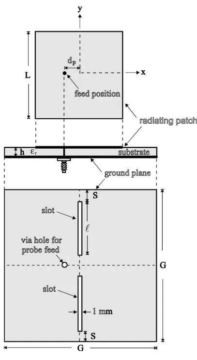
The air-substrate patch antenna with an annular-ring radiating patch of outer radius R1 and inner radius R2 is shown in Fig. 1(a). The thickness of the air substrate is h, and a probe feed is placed at a distance dp away from the patch center. Figure 1(b) shows
the geometry of the PBG ground plane studied. The square ground plane of dimensions G × G is embedded with a square lattice of 3 × 3 circular slots. The spacing between two adjacent slots, which is the period of the PBG structure in the ground plane, is denoted as S, and the radius of the embedded slots is r. Also note that
optimum stopband depth and passband ripples [8], and the center frequency f0 of the stopband is determined from
f0 = c/2S (1)
where c is the speed of light in free space.
The slotted ground plane studied is shown in Fig. 1(c). The four circular slots embedded in the ground plane have the same radius and spacing as those embedded in the PBG ground plane shown in Fig. 1(b), and are placed in diagonal directions, which are in perpendicular to the excited surface current path of the TM21 mode. The major difference of the slotted ground plane to the PBG ground plane is that the four embedded circular slots are located almost under the annular-ring radiating patch.
3. EXPERIMENTAL RESULTS AND DISCUSSION
The annular-ring patch antennas with a PBG ground plane and a slotted ground plane were constructed and studied. A reference antenna with a regular ground plane (no embedded slots) was also constructed. Measured return loss of the constructed antennas is shown in Fig. 2. The corresponding measured data for the antennas with a regular ground plane, a slotted ground plane, and a PBG ground plane are also listed in Table I for comparison. The annular-ring patch selected is with R1 = 55 mm and R2 = 23.2 mm, and the ground-plane size is 150 × 150 mm2 (G ×G). The thickness of
the air substrate is 3.2 mm. For all the antennas studied, the TM21 mode is excited to obtain broadside-null or conical-pattern radiation. The PBG period is determined by Eq. (1) to be 62.5 mm to generate a stopband centered at about 2.4 GHz. To obtain the value of r/S to be 0.25, the 3 × 3 circular slots with a radius of 15.6 mm are embedded in the antenna’s ground plane to form a PBG structure. On the other hand, for the slotted ground plane, four circular slots with the same slot radius of 15.6 mm and the adjacent spacing of 62.5 mm as the PBG structure are embedded. From the obtained results, it is clearly seen that the resonant frequency of the antenna with a slotted
ground plane was greatly lowered, similar as that observed in [1], by about 20%, from 2380 to 1920 MHz. This resonant frequency lowering suggests that a 36% antenna size reduction can be achieved for the antenna with a slotted ground plane, compared to the antenna with a regular ground plane.
Conversely, the resonant frequency of the antenna with a PBG ground plane was slightly increased, from 2380 to 2460 MHz. This characteristic is probably due to the decreased effective pemittivity of the substrate caused by the embedded periodic circular slots. It is also observed that the impedance bandwidths, determined from 10-dB return loss, for both antennas with the slotted and PBG ground planes are larger than the antenna with a regular ground plane. This increased impedance bandwidth is largely due to the embedded circular slots in the ground plane, which causes a lowered quality factor for the antenna.
Figure 3 presents the measured radiation patterns in two principal planes. For the three antennas studied, good conical patterns are observed. The measured antenna gain is presented in Fig. 4. Among the three antennas studied, the antenna with a slotted ground plane has the largest peak antenna gain. However, the gain variations within the impedance bandwidth are also larger. As for the antenna with a PBG ground plane, the peak antenna gain is also slightly increased, compared to the reference antenna (the case with a regular ground plane), and the gain variations (less than 0.5 dBi) are smaller than those of the antenna with a slotted ground plane.
It is also noted that the backward radiation of the antenna with a slotted ground plane is greatly increased. From the experiments, the backward radiation is increased by about 7 dB, compared to the reference antenna. This behavior is partly owing to the embedded slots in the ground plane and partly because the electrical size of the ground plane is decreased with the decreasing of the antenna’s resonnat frequency. On the other hand, it seems that the PBG ground plane can provide as a metallized surface, and a F/B ratio of about 9 dB larger than that of the antenna with a slotted ground plane (12.1 vs. 3.2 dB) is obtained. The obtained F/B ratio for the antenna with a PBG ground plane is even larger than that of the antenna with a regular ground
plane.
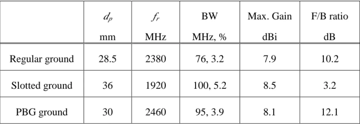
Table I: Performances of the antennas with regular, slotted, and PBG ground planes; antenna parameters are given in Fig. 2. fr is the resonant frequency of the TM21 mode. F/B ratio denotes the front-to-back maximum radiation intensity ratio.
dp mm fr MHz BW MHz, % Max. Gain dBi F/B ratio dB Regular ground 28.5 2380 76, 3.2 7.9 10.2 Slotted ground 36 1920 100, 5.2 8.5 3.2 PBG ground 30 2460 95, 3.9 8.1 12.1 4. CONCLUSIONS
We have presented an experimental study of the characteristics of an air-substrate annular-ring patch antenna with a slotted and a PBG ground plane. From the experimental results, it is observed that the antenna with a slotted ground plane can have the advantages of size reduction and bandwidth enhancement. However, decreased F/B ratio is also obtained. Conversely, although no size reduction is obtained for the antenna with a PBG ground plane, bandwidth enhancement is also observed. In addition, small gain variations within the obtained impedance bandwidth and improved F/B ratio are seen for the antenna with a PBG ground plane.
REFERENCES
10. J. S. Kuo and K. L. Wong, A compact microstrip antenna with meandered slots in the ground plane, Microwave Opt Technol Lett 29 (2001), 95-97.
11. T. H. Liu, W. X. Zhang, M. Zhang, and K. F. Tsang, Low profile spiral antenna with PBG substrate, Electron Lett 36 (2000), 779-780.
patch antennas on high-dielectric substrate, 1999 IEEE Antennas Propagat Soc Int Symp Dig, pp. 1920-1923.
13. R. Gonzalo, P. de Maagt, and M. Sorolla, Enhanced patch-antenna performance by suppressing surface waves using photonic-bandgap substrate, IEEE Trans Microwave Theory Tech 47 (1999), 2131- 2138.
14. Y. Horii and M. Tsutsumi, Harmonic control by photonic bandgap on microstrip patch antenna, IEEE Microwave Guided Wave Lett 9 (1999), 13-15.
15. S. Y. Lin and K. L. Wong, A conical-pattern annular-ring microstrip antenna with a photonic bandgap ground plane, Microwave Opt Technol Lett 31 (2001). (to appear in Aug. 5, 2001 issue)
16. A. Das, S. K. Das, and S. P. Mathur, Radiation characteristics of higher-order modes in microstrip ring antenna, IEE Proc H 131 (1984), 102-106.
17. V. Radisic, Y. Qian, R. Coccioli, and T. Itoh, Novel 2-D photonic bandgap structure for microstrip lines, IEEE Microwave Guided Wave Lett 8 (1998), 69-71.
Figure Captions Figure
1. (a) Geometry of an air-substrate annular-ring patch antenna. (b) The PBG ground plane. (c) The slotted ground plane.
2. Measured return loss against frequency for the antennas with a regular ground plane, a slotted ground plane, and a PBG ground plane; R1 =55 mm, R2 = 23.2 mm, G = 150 mm, S = 62.5 mm, r = 15.6 mm, h = 3.2 mm.
3. Measured radiation patterns in two principal planes. (a) Antenna with a regular ground plane at 2380 MHz. (b) Antenna with a slotted ground plane at 1920 MHz. (c) Antenna with a PBG ground plane at 2460 MHz.
4. Measured antenna gain against frequency. (a) Antenna with a regular ground plane. (b) Antenna with a slotted ground plane. (c) Antenna with a PBG ground plane.