從多媒體的視覺化需求描述轉譯為UML設計描述之轉譯器設計及實作
88
0
0
全文
(2) 從多媒體的視覺化需求描述轉譯為 UML 設計描述之轉譯器 設計及實作. The Design and Implementation of a Translator for Translating Multimedia Visual Requirements Representation into UML Representation 研 究 生:張正隆. Student:Cheng-Lung Chang. 指導教授:陳登吉 博士. Advisor:Deng-Jyi Chen. 國立交通大學 資訊學院. 資訊學程. 碩士論文. A Thesis Submitted to College of Computer Science National Chiao Tung University in partial Fulfillment of the Requirements for the Degree of Master of Science in Computer Science February 2008 Hsinchu, Taiwan, Republic of China. 中華民國 九十七 年 二 月.
(3) 從多媒體的視覺化需求描述轉譯為 UML 設計描述之 轉譯器設計及實作 學生:張正隆 國 立 交 通 大 學. 指導教授:陳登吉 博士 資 訊 學 院 摘. 資 訊 學 程 碩 士 班. 要. 在軟體開發過程中,誘導及確認使用者需求是一重要的階段。許多研 究指出[1-3],以視覺化的方式,不但可以即早獲得使用者的需求回饋以 及快速地確認使用者的需求;同時可避免因閱讀大量的文字需求描述而產 生的誤解。確定使用者需求後,緊接著進入分析、設計階段。目前以 UML[5]作為分析、設計的工具,已成為一種趨勢。然而,可能因不正確的 需求、或因知識領域的不同、或因開發者本身的經驗,而導致必須一再地 修正使用者案例圖(Use Case Diagram),進而連帶影響整個軟體開發流 程。 有鑑於此,本論文引用多媒體視覺化需求描述建構系統[1]來即早搜 集、確定使用者需求。並著重於研究將多媒體的視覺化需求描述轉譯為 UML 設計描述之方法,以改善軟體開發流程。在此研究中細分幾個重要步 驟,如轉譯規則的建立,系統模型設計等,也將在此研究一一地加以闡 述。 為了驗證及展示此研究的可行性,我們實作一個轉譯器,將視覺化需 求描述轉譯為 UML 設計描述;並以 XML Metadata Interchange(XMI)格式 [6]來貯存,使之得以 UML CASE Tool 來呈現 UML Diagrams。此轉譯器亦 從 XMI 資料產生相關程式碼。使用 UML CASE Tool 產生程式碼框架後,可 參考相關程式碼來建構 target system。如此,進而可改善軟體開發流 程。. I.
(4) The Design and Implementation of a Translator for Translating Multimedia Visual Requirements Representation into UML Representation Student: Cheng-Lung Chang. Advisor: Dr. Deng-Jyi Chen. Degree Program of Computer Science National Chiao Tung University Abstract In the software system development, eliciting the requirements from user is an important phase. It had been shown that using visual approach to represent user requirements not only can receive user’s early feedback for obtaining user’s correct requirements, but also can avoid reading large amount of text-based requirements that usually lead to misunderstand on requirements between user and developer [1-2]. After requirement discovery phase, software developers will start analyzing and designing the target software system. Using Unified Modeling Language (UML) approach [5] to analyze and design the target system become more and more popular. However, due to the incorrect user requirements, domain knowledge issues, or limitation on software developer’s experience, Revision of requirement become unavoidable. Eventually, the whole software development process will be affected. In view of that, this thesis quotes the visual requirement authoring system (VRAS) [1] to resolve above-mentioned issues such that we can collect and confirm user requirement as early as possible. This thesis research focuses on the translation of multimedia visual requirement representation into UML representation such that the software development process can be improved. There are important issues (such as translating rules building and proposed system model presenting) will be elaborated in this thesis. To demonstrate the applicability of the proposed model, a translation system is designed and implemented for translating multimedia visual requirements representation into UML representation. The target code is saved as XML Metadata Interchange (XMI) format [6], which can be used to represent UML notations by UML CASE Tool. Through this translation system, we generate the UML design representation automatically. Developer can use UML CASE tool to generate code framework to reconstruct the target system. Eventually, we can improve software development process.. II.
(5) 誌. 謝. 本論文承蒙指導教授陳登吉老師的耐心指導與教誨下,得以順利完 成。特別是最後階段,陳老師更是不厭其煩地給予研究上正確的引導,在 此致上對老師無限的感謝。 另外也感謝同實驗室的承一同學,在研究過程中相互的鼓勵與協 助。 最後我要感謝的是我的家人(尤其是媽媽)及琦婷,感謝她們總是在背 後默默地支持我、鼓勵我。謝謝。. III.
(6) Contents 摘. 要 ..........................................................................................................................I. ABSTRACT.................................................................................................................II 誌. 謝 .....................................................................................................................III. CONTENTS............................................................................................................... IV LIST OF FIGURES ................................................................................................... VI LIST OF TABLES ................................................................................................... VIII CHAPTER 1 INTRODUCTION...................................................................................1 1.1 Motivation................................................................................................................................................................ 1 1.2 The goal of this thesis............................................................................................................................................. 2 1.3 Organization of this thesis...................................................................................................................................... 3. CHAPTER 2 RELATED WORK .................................................................................4 2.1 Unified Modeling Language (UML)..................................................................................................................... 4 2.2 Visual Requirement Authoring System (VRAS)................................................................................................. 6 2.3 XML Metadata Interchange (XMI)....................................................................................................................... 7. CHAPTER 3 SYSTEM ANALYSIS AND SYSTEM MODEL .....................................10 3.1 System Analysis .................................................................................................................................................... 12 3.1.1 VRAS Script.................................................................................................................................................. 12 3.1.2 Translating rules analysis ............................................................................................................................. 14 3.1.3 Translating rules examples........................................................................................................................... 16 3.2 Translation System Responsibilities ................................................................................................................... 22 3.3 Proposed Translation System Model .................................................................................................................. 23 3.4 Architecture Model ............................................................................................................................................... 24. CHAPTER 4 SYSTEM DESIGN AND IMPLEMENTATION ....................................26 4.1 System Architecture.............................................................................................................................................. 26 4.2 System Structure ................................................................................................................................................... 27. IV.
(7) 4.3 System Conceptual model and Detail Design.................................................................................................... 28 4.3.1 Controller package........................................................................................................................................ 29 4.3.2 Model package .............................................................................................................................................. 32 4.3.3 View package................................................................................................................................................ 33 4.4 Related implementation issues ............................................................................................................................ 38 4.4.1 Development environment, cooperating tools, and limitation................................................................. 38 4.4.2 User Interface (UI) introduction.................................................................................................................. 39. CHAPTER 5 DEMONSTRATION AND APPLICATION EXAMPLES......................41 5.1 Demonstrating procedure ..................................................................................................................................... 41 5.2 Example - A video player UI application system.............................................................................................. 42 5.2.1 Multimedia Visual requirements representation by VRAS tool.............................................................. 42 5.2.2 XMI translating operation for XMI File generation ................................................................................. 45 5.2.3 UML representation through UML CASE Tool ....................................................................................... 47 5.2.4 Sample code generation through translation system................................................................................. 53 5.2.5 Verification of UML diagram ..................................................................................................................... 54. CHAPTER 6 CONCLUSION AND FUTURE WORK ................................................59 6.1 Conclusion of this thesis study ............................................................................................................................ 59 6.2 Future Work........................................................................................................................................................... 59. REFERENCE ............................................................................................................61 APPENDIX A VIDEO PLAYER UI APPLICATION CONSTRUCTION THROUGH VRAS TOOL .............................................................................................................63 A.1 User requirements description ............................................................................................................................ 63 A.2 Scenes creation and actor layout ........................................................................................................................ 63 A.3 Interaction editing ................................................................................................................................................ 65 A.4 Function binding .................................................................................................................................................. 66. APPENDIX B VRAS SCRIPTS FOR VIDEO PLAYER UI APPLICATION SYSTEM ..................................................................................................................................68 APPENDIX C UML DIAGRAM REPRESENTATION FOR VIDEO PLAYER UI APPLICATION SYSTEM ..........................................................................................77. V.
(8) List of Figures FIGURE 1 THE GENERAL SOFTWARE PROCESS USING UML NOTATIONS ....................................................... 1 FIGURE 2 THE GAP BETWEEN REQUIREMENT AND DESIGN REPRESENTATION........................................... 2 FIGURE 3 RESEARCH WORK IN THIS THESIS ........................................................................................................... 2 FIGURE 4 VISUAL REQUIREMENT AUTHORING SYSTEM [1] ............................................................................... 7 FIGURE 5 XMI INTEGRATE THREE INDUSTRY STANDARDS ............................................................................... 7 FIGURE 6 REDUCING COMMUNICATION COMPLEXITIES AMONG APPLICATIONS THROUGH XMI [9] ... 8 FIGURE 7 A TRANSLATING FLOW............................................................................................................................. 10 FIGURE 8 A DETAILED PROCESS OF THE PROPOSED TRANSLATION SYSTEM ............................................ 11 FIGURE 9 COMPONENTS OF THE TRANSLATION PROCESS ............................................................................... 12 FIGURE 10 THE STRUCTURE OF THE VRAS SCRIPT FILE.................................................................................... 13 FIGURE 11 GENERAL CONNECTIVE RELATIONS AMONG SCENES [1] ............................................................ 13 FIGURE 12 VRAS STORY CLASSIFIED BY SPATIAL AND TEMPORAL.............................................................. 15 FIGURE 13 UML DIAGRAM CLASSIFIED BY STRUCTURE AND BEHAVIOR ................................................... 15 FIGURE 14 AN EXAMPLE OF MAPPING FROM SCRIPT INTO STATE DIAGRAM OF UML ............................ 17 FIGURE 15 AN EXAMPLE OF MAPPING FROM ACTORS INTO CLASS DIAGRAM .......................................... 18 FIGURE 16 AN EXAMPLE OF SEQUENCE REPRESENTATION MAPPING INTO SEQUENCE FRAGMENT OF SEQUENCE DIAGRAM......................................................................................................................................... 19 FIGURE 17 AN EXAMPLE OF PARALLEL REPRESENTATION MAPPING INTO PARALLEL FRAGMENT OF SEQUENCE DIAGRAM......................................................................................................................................... 19 FIGURE 18 AN EXAMPLE OF REPEAT REPRESENTATION MAPPING INTO LOOP FRAGMENT OF SEQUENCE DIAGRAM......................................................................................................................................... 20 FIGURE 19 AN EXAMPLE OF CONDITION REPRESENTATION MAPPING INTO ALTERNATIVE COMBINATION FRAGMENT OF SEQUENCE DIAGRAM FOR “IF-ELSE"............................................. 21 FIGURE 20 AN EXAMPLE OF ALTERNATIVE REPRESENTATION MAPPING INTO ALTERNATIVE COMBINATION FRAGMENT OF SEQUENCE DIAGRAM FOR “SWITCH - CASE".............................. 22 FIGURE 21 THE PROPOSED TRANSLATING FLOW ................................................................................................ 22 FIGURE 22 THE PROPOSED TRANSLATION SYSTEM MODEL OF THIS THESIS ............................................. 23 FIGURE 23 THE ARCHITECTURE MODEL................................................................................................................. 25 FIGURE 24 THE MVC ARCHITECTURE OF TRANSLATION SYSTEM ................................................................. 26 FIGURE 25 THE STRUCTURE OF TRANSLATION SYSTEM................................................................................... 27 FIGURE 26 CONCEPTUAL MODEL OF THE PROPOSED TRANSLATION SYSTEM........................................... 29 FIGURE 27 UML MODEL CREATION FLOW ............................................................................................................. 30 FIGURE 28 THE PROCESS OF BUILDING VRAS PARSER TREE AND GENERATE TARGET UML DIAGRAMS ............................................................................................................................................................ 30 FIGURE 29 AN EXAMPLE OF UML CLASS NOTATION REPRESENTED BY THREE XMI ELEMENTS ......... 32 FIGURE 30 THE HIERARCHY OF UML/XMI MODEL ELEMENTS ........................................................................ 33 FIGURE 31 THE XMI FILE REPRESENTATION FLOW............................................................................................. 34 FIGURE 32 THE PARTIAL XMI FILE OUTPUTTED BY XMIFILE CLASS............................................................. 35 FIGURE 33 AN EXAMPLE OF BY XMI TREE REPRESENTATION ........................................................................ 36 FIGURE 34 THE RELATIONSHIP BETWEEN UML MODEL, XMI AND CODE FRAMEWORK ......................... 37 FIGURE 35 THE SAMPLE CODE REPRESENTATION FLOW................................................................................. 38 FIGURE 36 THE UI OF XMI FILE GENERATION....................................................................................................... 39 FIGURE 37 THE UI OF SAMPLE CODE GENERATION ............................................................................................ 40 FIGURE 38 THE DEMONSTRATING PROCEDURE ................................................................................................... 42 FIGURE 39 UI-1 AND UI-2 FOR VIDEO PLAYER UI APPLICATION ..................................................................... 43 FIGURE 40 INTERACTION FOR VIDEO PLAYER UI APPLICATION .................................................................... 44 FIGURE 41 PARTIAL SCRIPTS FOR VIDEO PLAYER BUTTON AND ITS SCENARIO....................................... 45 FIGURE 42 THE TRANSLATING PROCEDURE FROM VRAS SCRIPT INTO XMI FOR THE APPLICATION EXAMPLE OF THE UI VIDEO PLAYER APPLICATION................................................................................. 46 FIGURE 43 USING TRUFUN UML CASE TOOL TO REPRESENT UML DIAGRAMS .......................................... 47. VI.
(9) FIGURE 44 CLASS DIAGRAM FOR INHERITANCE-HIERARCHY OF SCENES................................................... 48 FIGURE 45 FINITE STATE MACHINE DIAGRAM FOR SCENES BRANCH .......................................................... 49 FIGURE 46 CLASS DIAGRAM FOR CAST HIERARCHY WITHIN SCENE 1 ......................................................... 50 FIGURE 47 SEQUENCE DIAGRAM FOR GO TO “SCENE 2" .............................................................................. 51 FIGURE 48 LINK A WEB PAGE .................................................................................................................................... 51 FIGURE 49 CLASS DIAGRAM FOR CAST HIERARCHY WITHIN SCENE 2 ......................................................... 52 FIGURE 50 SEQUENCE DIAGRAM FOR THE PRELUDE SCENARIO OF SCENE 2............................................. 52 FIGURE 51 SEQUENCE DIAGRAM FOR PLAY VIDEO SCENARIO....................................................................... 53 FIGURE 52 STEPS OF THE CODE GENERATION OF THE EXAMPLING APPLICATION SYSTEM ................. 54 FIGURE 53 THE PROPOSED TRANSLATING PROCESS .......................................................................................... 55 FIGURE 54 THE VERIFICATION FLOW FOR REPRESENTED UML DIAGRAM.................................................. 55 FIGURE 55 STEPS FOR CODE GENERATION THROUGH UML CASE TOOL ...................................................... 56 FIGURE 56 FILL INTO CODE IN THE TFACTORY CLASS CONSTRUCTION TO NEW TWO SCENE INSTANCES............................................................................................................................................................ 57 FIGURE 57 FILL INTO CODE IN THE SCENE 1 CLASS CONSTRUCTION TO NEW ACTOR INSTANCES WITHIN SCENE 1 .................................................................................................................................................. 57 FIGURE 58 FILL INTO CODE IN THE HOOKONCLICK() OF TSC1BTNVP CLASS TO INVOKE “GOTO SCENE 2" ACTION.............................................................................................................................................. 57 FIGURE 59 FILL INTO CODE IN THE HOOKONCLICK() OF TSC2BTNPLAY CLASS TO CALL ITS RELATED DLL FILE. ............................................................................................................................................................... 57 FIGURE 60 THE RESULT OF RECONSTRUCTED VIDEO PLAYER UI APPLICATION ..................................... 58 FIGURE 61 MAIN UI OF VRAS TOOL ......................................................................................................................... 64 FIGURE 62 IMPORT PICTURE DIALOG...................................................................................................................... 64 FIGURE 63 SCENE 1 AND SCENE 2 FOR VIDEO PLAYER UI APPLICATION..................................................... 65 FIGURE 64 EDIT SCENE 1 AND SCENE 2 RELATIONSHIPS FOR VIDEO PLAYER UI APPLICATION .......... 66 FIGURE 65 SCENE 1 AND SCENE 2 INTERACTION RELATIONSHIPS................................................................. 66 FIGURE 66 VIDEO PLAYER UI APPLICATION ......................................................................................................... 67 FIGURE 67 CLASS DIAGRAM FOR STORY SCENES HIERARCHY....................................................................... 77 FIGURE 68 STATE DIAGRAM STORY SCENES BRANCH....................................................................................... 77 FIGURE 69 CLASS DIAGRAM FOR ACTORS HIERARCHY WITHIN SCENE 1.................................................... 77 FIGURE 70 SEQUENCE DIAGRAM FOR “VIDEO PLAY" SCENARIO IN THE SCENE 1 ............................... 77 FIGURE 71 SEQUENCE DIAGRAM FOR “HELP" SCENARIO IN THE SCENE 1 ............................................. 77 FIGURE 72 CLASS DIAGRAM FOR ACTORS HIERARCHY WITHIN SCENE 2.................................................... 77 FIGURE 73 SEQUENCE DIAGRAM FOR “PRELUDE" SCENARIO OF SCENE 2 ........................................... 77 FIGURE 74 SEQUENCE DIAGRAM FOR “BACK" SCENARIO IN THE SCENE 2........................................... 77 FIGURE 75 SEQUENCE DIAGRAM FOR “PLAY VIDEO" SCENARIO IN THE SCENE 2............................. 78 FIGURE 76 SEQUENCE DIAGRAM FOR “IMAGE ZOOM IN" SCENARIO IN THE SCENE 2...................... 78 FIGURE 77 SEQUENCE DIAGRAM FOR “IMAGE NORMAL SIZE" SCENARIO IN THE SCENE 2............ 78 FIGURE 78 SEQUENCE DIAGRAM FOR “IMAGE ZOOM OUT" SCENARIO IN THE SCENE 2.................. 78 FIGURE 79 SEQUENCE DIAGRAM FOR “SOUND PLUS" SCENARIO IN THE SCENE 2 ............................ 78 FIGURE 80 SEQUENCE DIAGRAM FOR “SOUND MINUS" SCENARIO IN THE SCENE 2 ......................... 78. VII.
(10) List of Tables TABLE 1 UML DIAGRAMS AND THEIR PURPOSES.................................................................................................. 5 TABLE 2 THE CORRESPONDING RELATIONSHIPS BETWEEN VRAS SCRIPT AND UML DIAGRAM ......... 16 TABLE 3 IMAGE AND ITS FUNCTION........................................................................................................................ 65 TABLE 4 ACTORS AND ITS BINDING DLL FILE LIST ............................................................................................ 66. VIII.
(11) Chapter 1 Introduction 1.1 Motivation Using Object Oriented concept to construct and develop software system has become more and more popular. Consequently, the Unified Modeling Language (UML) [5] becomes the de facto standard to represent object-oriented analysis and design. Figure 1 illustrates the general process for the software system development by UML. In the Analysis phase, developers use Use-Case Model to represent functional requirements. At the same time, developers also build the Domain Model according to the domain knowledge and requirements description. In the design phase, developers usually use Class Diagram to represent the system static view and use Sequence Diagram to represent system dynamic view.. Figure 1 The general software process using UML notations From above general software process, we find that user and system requirements are depicted using natural language and then are mapped into UML representation eventually generated the target codes using code generation tool. There is a big gap from requirements analysis to code, and design is used to bridge the gap. User requirements always change. Once requirement is changed, developer must re-analysis, re-design, and re-coding. All stages of process must be repeated again. Figure 2 illustrates that there exists the big gap between user requirements and UML design representation. 1.
(12) User Requirements. UML Representation. Big Gap. Figure 2 The gap between requirement and design representation The incomplete requirements, inaccurate requirements, the big gap between analysis phase and design phase can spend developers a lot of design time. It has been shown that multimedia visual requirements representation is better than traditional text-based requirements representation [1]. The text-based requirements are easy to result ambiguity due to the different domain knowledge between user and software developer. The multimedia visual requirements can be viewed as an animation sequence instead of reading text based user requirements. The multimedia visual requirements representation technique let users and software developer communicate more easily and let software developer receive early feedback of requirements from users. Section 2.2 gives more detailed information. However, even if determined requirements gathered, software developers still have to spend a lot of time to develop the software system under consideration.. 1.2 The goal of this thesis In order to reduce the gap between user functional requirements and UML design representation, this thesis takes visual requirements authoring system (VRAS) [1] to get multimedia visual requirements representation and research how to translate it into UML representation. Figure 3 illustrates the research work in this thesis. We focus on the translation from multimedia visual requirements representation into UML representation. Multimedia Visual Requirements Representation. User Requirements. Visual Requirement Authoring System. UML Representation. This thesis focus on this research work. Figure 3 Research work in this thesis. 2.
(13) 1.3 Organization of this thesis This thesis is organized as follows.. Chapter 1 introduces the research motivation, goal, and organization of this research work. Chapter 2 reviews some related work on co-design flow for the translation of multimedia visual requirements representation into UML representation. Chapter 3 gives the detailed feasibility study for translation, find out the responsibilities of translating system, and present the proposal system model. Chapter 4 designs the system architecture, defines the functional blocks of translating system and details the system implementation. Chapter 5 uses an example to demonstrate how to translate from multimedia visual requirement representation into UML representation and verify correctness of translated target code. Chapter 6 presents the conclusion in the research and possible future research directions.. 3.
(14) Chapter 2 Related Work In this chapter, the related works on co-design flow for the translation from multimedia visual requirement representation into UML representation are visited. Specifically, Unified Modeling Language (UML), Visual Requirements Authoring System (VRAS), and XML Metadata Interchange (XMI) are discussed.. 2.1 Unified Modeling Language (UML) The first version of UML [5] was created in November 1997 as standard language for object oriented analysis and design by OMG [22]. The UML has become a de facto standard for design model language. UML may be used to model structures and processes for many domains but it is most often associated with object-oriented software modeling. System analyst, software developers, project manager, customers, and vendors can communicate with common modeling language through UML and simplify the development process. UML can let user force on every aspect of system view and these resulting could evolve the system development life cycle. UML can describe a blueprint of real system that gives user and system designer a conceptual view for the whole system. According to the definitions by OMG [22], it has following characteristics: 1.. The UML uses tools to elicit better requirements. Either incomplete or inaccurate requirements are ubiquitous in the field of software development. It is composed of visualized graphical notation in most part so let user capture the information of system more easy.. 2.. The UML gives a way to determine whether it is the same as others' for understanding of the system. Because systems are more complex and have more different types of information that must be conveyed, it offers different diagrams specializing in the different types of information.. 4.
(15) 3.. It can be used to support system analysis and design phase, concept phase, and system implementation. Therefore, all project members, customers, and vendor can use UML to communicate with each other.. 4.. It is completely language independent and maybe used to model applications regardless of whether or not they are to be deployed in Java, C++, or any other languages.. The UML defines several different diagrams some for analysis, others for design, and still others for implementation or deployment. Table 1 illustrates that each diagram shows the relations among the different sets of entities, depending on the purpose of the diagrams during different phase. Here it is general catalog; actually, UML does not stipulate how to use those diagrams. The content of Table is referred to [10]. Table 1 UML Diagrams and their purposes Phase. Analysis phase. Use the UML Diagram Use Case diagrams, which involve entities interacting with the system (say, users and other systems) and the function points that what to implement.. Activity diagrams, which focus on workflow of the problem domain (the actual space where people and other agents are working, the subject area of the program) rather than the logic flow of the program. Class diagrams represent the relationships between the classes.. State diagrams represent the different states an object may be in as well as the transitions between these states. Design phase. Interaction diagrams show how specific objects interact with each other. Because they deal with specific cases rather than general situations, they prove helpful both when checking requirements and when checking designs. The most popular kind of Interaction diagram is the Sequence diagram.. Some basic modeling diagrams are recalled here: Class Diagram, Interaction Diagram, and State Machine Diagram. z Class Diagram: The most basic of UML diagrams is the Class diagram. It both describes classes and shows the relationships among them. It is design representation for static view.. 5.
(16) z Interaction Diagram: Class diagrams show static relationships between classes. In other words, they do not show us any activities. The diagram that shows how the object interacts with others is Interaction diagram. The most common type of Interaction diagram is the Sequence diagram. Sequence diagrams focus on the dynamic view and emphasize the timing of event occurred order. z State Machine Diagram: State machine shows the state of system or an object during its life cycle and the transition between states when external event occurred. Other diagrams are referred to [10, 13].. 2.2 Visual Requirement Authoring System (VRAS) Visual requirement authoring system [1] is a visual requirement representation technology. This system uses visual scenarios to depict requirements instead of reading amount of text-based representation of the requirements. Through this system, customer and system analyst can communicate not only in a more nature and in easy way, but also system analyst can receive early feedback of requirements from customers. Figure 4 shows the visual requirement authoring system. System analyst use VRAS to create visual forms and select Multimedia Reusable Components (MRCs) to construct customer requirements. When existing MRCs are not adequate to describe customer requirements, MRCs Manager uses the Component Constructor to add new MRCs to create new representation. System analyst also uses VRAS to play back the prototyping system to customer and capture customer’s requirements. Determined Requirements would be automatically converted into text script file including static and dynamic information by VRAS. This scripting language is designed and implemented by the Software Engineering Laboratory of NCTU [23].. 6.
(17) . Figure 4 Visual Requirement authoring system [1]. 2.3 XML Metadata Interchange (XMI) XML Metadata Interchange (XMI) [6] is a set of standards published by the OMG [22] in February 1999. It is used to interchange metadata among applications. XMI produces XML schema for any meta-model that is compliant with the OMG’s Meta Object Facility (MOF) and produces an XML document instantiating from the meta-model. The UML based modeling tools can exchange their metadata using XMI standards. XMI integrates three key industry standards: XML, UML, and OMF (See figure 5).. UML Understand. XML Exchange. XMI. MOF Manage Figure 5 XMI integrate three industry standards. 7.
(18) z. XML – eXtensible Markup Language, a W3c standard.. z. UML – Unified Modeling Language, an OMG modeling specification, with is now an ISO/IEC standard (ISO/IEC 19501).. z. MOF – Meta Object Facility (ISO/IEC 19502).. By using an industry standard for storing and sharing object programming information, development team using tools from multiple vendors can collaborate on applications. The XMI standard will allow developers to leverage the Web to exchange object-oriented data among applications, and to create secure, distributed applications built in a team development environment. Using XMI also could reduce the relation complexity between communications with applications [9]. Figure 6 illustrates the complexity reduced from. n2 − n. to n through XMI. format interchange. Originally, there are six applications (App1 to App6) and one needs to implement thirty relations totally. Every application must know the format of other five applications. Now, through XMI, every application just needs to face the only one format – XMI.. Figure 6 Reducing communication complexities among applications through XMI [9] XMI provides a basis for the development of XMI schema. It specifies the elements that should be declared in an XMI schema such as XMI header, XMI content and so on. The declarations are composed of XMI document structure. The following is the partial XMI document.. 8.
(19) <?xml version="1.0" encoding="UTF-8"?> <uml:Model xmi:version="2.1" xmlns:xmi="http://schema.omg.org/spec/XMI/2.1" xmlns:ecore="http://www.eclipse.org/emf/2002/Ecore" xmlns:trufun="http://trufun" xmlns:uml="http://www.eclipse.org/uml2/2.0.0/UML" xmi:id="f18310ed-5599-4bbe-9c49" name="model"> <eAnnotations xmi:id="38f9346d-481c-4f22-84f7" source="TaggedValues"> <details xmi:id="dd0f90e5-3476-4d1d-a39c" key="ProjectType" value="UML2Project"/> </eAnnotations> <eAnnotations xmi:id="e44e7723-1b99-47ce-850a" source="Diagrams"> … …….. <packagedElement xmi:type="uml:Class" xmi:id="7678db6b-504d-4be3-b1f2" name="TScene"> <eAnnotations xmi:id="e1ca4225-ea4e-46db-9345" source="TaggedValues"> <ownedOperation xmi:id="5e3f988e-1612-4b00-a3b2" name="Display" visibility="public"> <ownedParameter xmi:id="f4a677d4-555b-45a8-9e12" name="Parameter1" type="49899437-f107-4687-8083" direction="return"/> </ownedOperation> … ……... 9.
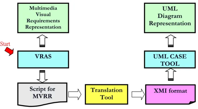
(20) Chapter 3 System Analysis and System model The goal of this research work focus on the translating of multimedia visual requirement representation into UML representation. Figure 7 illustrates translation flow from multimedia visual requirements representation to UML diagram representation. Multimedia Visual Requirements Representation. Translation Tool. UML Diagram Representation. Figure 7 A translating flow. In the translating flow, the input and output of translation tool are two chief considerations. Figure 8 depicts a detailed translation process in this thesis study. For the input of translation tool, Visual requirement authoring system (VRAS) produces multimedia visual requirements representation. It is considered as a communication bridge with users. VRAS can be used to create multimedia visual requirements. It helps system developer to capture user requirements and save those multimedia visual requirements representation (MVRR) as text-based script automatically. Translation tool uses this script as input. For the output of translation tool, we adopt XML Metadata Interchange (XMI) as target code. XMI can be used to represent UML notations by UML CASE Tool.. 10.
(21) Present. Visual Requirement Authoring System (VRAS). Save as. Multimedia Visual Requirements Representation. UML Diagram Representation. Script for MVRR. UML Notations. Translation Tool. XMI format. Figure 8 A detailed process of the proposed translation system Figure 9 presents components in the translation process. These components will be described in the following: VRAS: Visual requirement authoring system is visual requirements representation technology. It can represent user requirements by visual, provide an easy communication way between users and system analyst, and help system analyst to capture user requirements. MVRR: MVRR is the output of VRAS. It is multimedia visual representation. Script for MVRR: The script file is also the output of VRAS. VRAS saves those MVRR as text-based script language. Translation tool: This tool is in charge of translating from VRAS script into XMI format. XMI: It is the output of translation system and used to represent UML notations by UML CASE TOOL. UML CASE TOOL: It is a computer aided software engineering tool for UML. UML diagram representation: Represent UML diagram by UML through UML CASE TOOL. Specifically, we need to implement a tool that takes the script language generated by VRAS and produces the XMI corresponding script language.. 11.
(22) Multimedia Visual Requirements Representation. UML Diagram Representation. VRAS. UML CASE TOOL. Start. Script for MVRR. Translation Tool. XMI format. Figure 9 Components of the translation process. 3.1 System Analysis 3.1.1 VRAS Script Visual requirement authoring system saves multimedia visual requirements representation as text-based script file. Figure 10 illustrates the structure of the script file. In the script file, requirements are described as “Story”. A story includes at least one scene, and each scene may contain several actors and several scenarios. The actor is basic requirement multimedia reusable component (MRC) to represent a requirement segment. It can be an image, video, sound, or text. The scenario may represent the interaction among actors, the prelude, and finale of one scene and branch among scenes. The detailed information is referred to [1].. 12.
(23) Story. Scene. Actor Actor Actor (MRC). Scenario Scenario Scenario. Figure 10 The structure of the VRAS script file. Within multimedia visual requirements, there may have several scenes. Script file also can represent the branch among scenes in the scenario. Figure 11 shows the three kinds of general connective relations among scenes, which are required to be mapped into the UML corresponding representations. Scene 1. Scene 1. … Scene 1. (a) List Scene 2. Scene 1. Scene 2. Scene 3. Scene 4. Scene 3. Scene 5 (c) Tree. (b) Graph. Figure 11 General connective relations among scenes [1]. 13.
(24) 3.1.2 Translating rules analysis In general, the program language is composed of data declaration and control statement. The data declaration defines data structure in the design phase. The data structure is a kind of static view of the system. The control statement is program of the system. It is a dynamic view of the system. The program is a serial of flow control to present the system behavior. In section 3.1.1, we have introduced the VRAS script structure. The script structure is composed of Scenes, MRCs, and interaction relationship among them (scenarios). Scenes and MRCs present the structure view of the system, and scenarios present behavior view of the system. Therefore, we can classify the content of VRAS script according to spatial and temporal relationship. The same, we can classify UML diagram according to structure and behavior. Through classification, we can find the mapping relationship easy between VRAS script and UML diagram. VRAS script can be classified according to spatial and temporal relationship. Figure 12 shows the catalog by tree structure. For spatial view, one story contains at least one scene. Each scene may contain several actors and their relationship. Each actor has its properties and operations. For temporal view, one story may have different scenario levels. For story (system) level, there are scenarios to describe the translation among scenes. For scene level, each scene has two special scenarios named prelude and finale. System invokes a prelude scenario before enter one scene and execute a finale scenario before exit one scene. For scene internal level, there are several actor scenarios. Actor scenario describes user events and interaction among actors. Story Spatial Scene (container) Multimedia Actor. Temporal Scenario. Actor scenario Scene scenario (prelude/finale) Story scenario (scenes branch). 14.
(25) Figure 12 VRAS Story classified by spatial and temporal. The same as above, UML diagrams can be classified according to structure and behavior [13]. Figure 13 shows the catalog by tree structure. The common structure diagram defined in the UML is class diagram. Class diagram is composed of several classes and relationships among classes. It is static view of system. For the dynamic view of system, there are two common behavior diagrams defined in the UML. They are sequence diagram and state machine diagram. Sequence diagram presents the interaction among objects of system. State machine diagram emphasizes the state and state translation within object or system. From the view for VRAS story and UML diagram classified, there exist some mapping rules. When a scene is viewed as a container, it is mapped into class diagram. The actors within scene are mapped into classes. Actor’s properties and operations are mapped into “attributes” and “operations” of class. At the same time, abstracting for different actors is necessary. Actor scenarios, prelude and finale scenarios are suitable to map into sequence diagram. Actor within scenario is mapped into “object” notation of sequence diagram. The user event and interaction among actors are mapped into “call” or “message” notation. For special interaction representation, for example, parallel presentation, repeat presentation, and condition presentation, we can use “combined fragment” notation to emphasis them. For story scenario, we can use state diagram to represent branch among scenes. Here, a scene would be regard as one state. Diagram Structure Class diagram Class. … Behavior. Sequence diagram State diagram. … Figure 13 UML diagram classified by structure and behavior. 15.
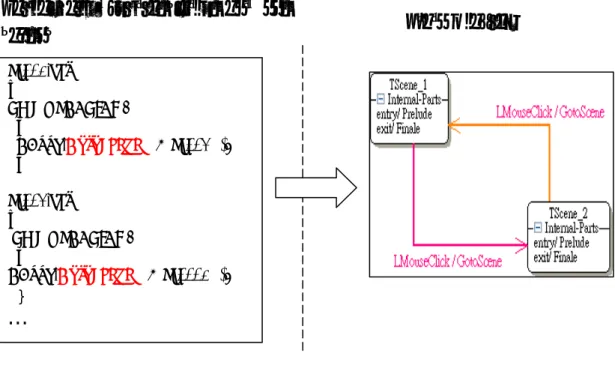
(26) Table 2 summarizes the corresponding relationships between VRAS script and UML diagram. Table 2 The corresponding relationships between VRAS script and UML Diagram. VRAS Script Scene as container Multimedia actor Actor’s event Actor’s operation Actor’s properties Actors scenario Scenes scenario (prelude/finale) Actor Interaction between actors sequential presentation parallel presentation repeat presentation condition presentation Story scenario (scenes branch) Scene Scenes branch Prelude of scene Finale of scene. UML Diagram UML Class Diagram Class Operation of class Attributes of class UML Sequence Diagram Object notation Call or Message combined fragment w/ different operator (seq, par, loop, alt) State Diagram State transition of state Enter action of state Exit action of state. 3.1.3 Translating rules examples In the section, we use several examples to illustrate the translating rules. The first example is for system scenario. The scene of story is viewed as a state of system. Now scene is mapped into “state” notation and scene branch is mapped into “transition” notation. The prelude of scene is mapped into “entry action” of state and the finale of scene is mapped into “exit action”. The interaction within scene can be mapped into “do action” of state. Using state diagram to represent scene branches of whole system is suitable. Figure 14 illustrates an example of mapping from scripts to state diagram of UML. Form partial script; there are two scenes named “Sc001” and “Sc002”. “GotoScene” keyword presents the scene branch when LMOUSECLICK event trigged by user. Therefore, branches between “Sc001” and “Sc002” will be translated into state transitions.. 16.
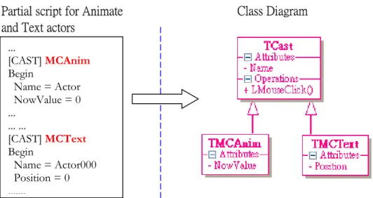
(27) Partial script for translation between scenes. State Diagram. Sc001.ebs … LMOUSECLICK: { EBook.GotoScene( "@Sc002" ); } Sc002.ebs … LMOUSECLICK: { EBook.GotoScene( "@Sc0001" ); }. …. Figure 14 An example of mapping from script into State Diagram of UML. A scene also can be viewed as a container including many actors. Now scene is mapped into “class diagram” and actors are mapped into “class”. The actor’s properties are mapped into class attributes and events are mapped into class operations. Figure 15 illustrates an example of mapping actors into class notation. In the partial script, there are two actors named “MCAnim” and “MCText”. They are mapped into TMCAnin and TMCText classes. At the same time, an abstract class named TCast is also presented. Both classes should inherit from “TCast” class. Two actors’ properties are mapped into their attributes. The common parts (events and properties) of two actors would be extracting to their abstract layer class named TCast.. 17.
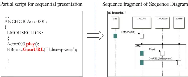
(28) Class Diagram. Partial script for Animate and Text actors ... [CAST] MCAnim Begin Name = Actor NowValue = 0 ... ... ... [CAST] MCText Begin Name = Actor000 Position = 0 ........ Figure 15 An example of mapping from actors into class diagram. Either prelude/finale scenario or interactive scenario with user is mapped into interaction of “sequence diagram”. The actor in the scenario is mapped into “object” notation of sequence diagram. The behavior between actors can be mapped into “call” or “message” notation. Figure 16 to 20 present five general requirements representation cases.. Figure 16 illustrates an example of mapping rule from sequence representation in VRAS script and the “sequence combined fragment” notation of sequence diagram in the UML. In the VRAS partial script, it shows the sequence representation (Actor000.play and EBook.GotoURL in order) after user click Actor001 through left button of mouse (LMOUSECLICK). Therefore, there are four objects - User, TMCText (Actor001), TMMovie (Actor000), and TScene (EBook) in the sequence diagram. The event invoked by user clicks mouse is mapped into “LMouseClick” function-call notation. Two executed actions are also mapped into function-calls notation. We use “sequence combination fragment” notation with represented two executed actions within the same “interaction operand” notation to emphasize two actions executed in order.. 18.
(29) Sequence fragment of Sequence Diagram. Partial script for sequential presentation … ANCHOR Actor001 : { LMOUSECLICK: { Actor000.play(); EBook..GotoURL( "labscript.exe"); }. …. Figure 16 An example of sequence representation mapping into sequence fragment of sequence diagram Figure 17 illustrates an example of mapping rule from parallel representation in VRAS script and the “parallel combined fragment” notation of sequence diagram in the UML. In the VRAS partial script, it shows the parallel representation (Actor000.play and EBook.GotoURL paralleled. execution). after. user. click Actor001. through. left. button. of. mouse. (LMOUSECLICK). Therefore, there are four objects - User, TMText (Actor001), TMMovie (Actor000) and TScene (EBook) in the sequence diagram. The event invoked by user clicks mouse is mapped into “LMouseClick” function-call notation. Two executed actions are also mapped into function-calls notation. We use “parallel combination fragment” notation with represented two actions executed in the different “interaction operand” notation to emphasize two actions executed at the same time. Parallel fragment of Sequence diagram. Partial script for parallel presentation … ANCHOR Actor001 : { LMOUSECLICK: { parallel( Actor000.play(), EBook.GotoURL( "labscript.exe"); }. .. …. Figure 17 An example of parallel representation mapping into parallel fragment of sequence diagram 19.
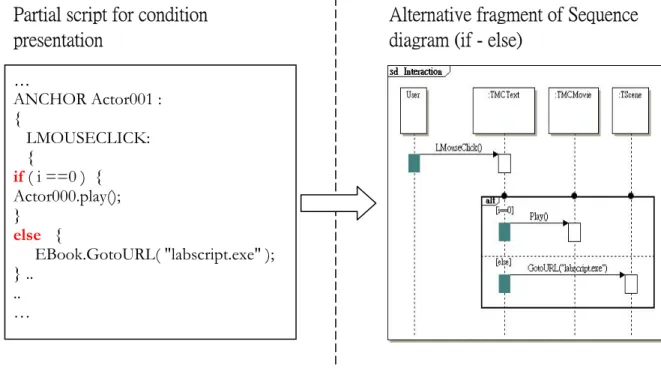
(30) Figure 18 illustrates an example of mapping rule from repeat representation in VRAS script and the “loop combined fragment” notation of sequence diagram in the UML. In the VRAS partial script, it shows the repeat representation (Actor000.play and EBook.GotoURL repeated 6 times) after user click Actor001 through left button of mouse (LMOUSECLICK). Therefore, there are four objects - User, TMCText (Actor001), TMMovie (Actor000) and TScene (EBook) in the sequence diagram. The Invoked event by user clicks mouse is mapped into “LMouseClick” function-call notation. Two executed actions are also mapped into function-calls notation. We use “loop combination fragment” notation with represented two actions executed in the same interaction operand notation to emphasize two actions executed in specific looping.. Loop fragment of Sequence diagram. Partial script for repeat presentation … ANCHOR Actor001 : { .. LMOUSECLICK: { repeat(6){ Actor001.play(); EBook.GotoURL( "labscript.exe" ) ; } }. Figure 18 An example of repeat representation mapping into loop fragment of sequence diagram Figure 19 illustrates an example of mapping rule from condition representation in VRAS script and the “alternative combined fragment” notation of sequence diagram in the UML. In the VRAS partial script, it shows the condition representation (if - else condition) after user click Actor001 through left button of mouse (LMOUSECLICK). Therefore, there are four objects - User, TMCText (Actor001), TMMovie (Actor000), and TScene (EBook) in the sequence diagram. The event invoked by user clicks mouse is mapped into “LMouseClick” function-call notation. We use “alternative combination fragment” notation with represented two actions executed in the different interaction operand notation. Regard condition as the guard of the first interaction operand and add specific guard named ‘else’ to second interaction operand to emphasize two actions executed under specific condition. 20.
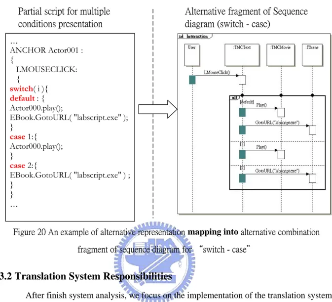
(31) Partial script for condition presentation. Alternative fragment of Sequence diagram (if - else). … ANCHOR Actor001 : { LMOUSECLICK: { if ( i ==0 ) { Actor000.play(); } else { EBook.GotoURL( "labscript.exe" ); } .. .. …. Figure 19 An example of condition representation mapping into alternative combination fragment of sequence diagram for “if-else” Figure 20 illustrates an example of mapping rule from multiple cases representation in VRAS script and the “alternative combined fragment” notation of sequence diagram in the UML. In the VRAS partial script, it shows the multiple cases representation (switch - case) after user click Actor001 through left button of mouse (LMOUSECLICK). Therefore, there are four objects - User, TMCText (Actor001), TMMovie (Actor000), and TScene (EBook) in the sequence diagram. The event invoked by user clicks mouse is mapped into “LMouseClick” function-call notation. We use “alternative combination fragment” notation with represented two executed actions in the different interaction operand notation under different case. Add specific guard named “default” to first interaction operand and add guard for each case interaction operand to emphasize different case has its specific composed actions.. 21.
(32) Partial script for multiple conditions presentation. Alternative fragment of Sequence diagram (switch - case). … ANCHOR Actor001 : { LMOUSECLICK: { switch( i ){ default : { Actor000.play(); EBook.GotoURL( "labscript.exe" ); } case 1:{ Actor000.play(); } case 2:{ EBook.GotoURL( "labscript.exe" ) ; } } …. Figure 20 An example of alternative representation mapping into alternative combination fragment of sequence diagram for “switch - case". 3.2 Translation System Responsibilities After finish system analysis, we focus on the implementation of the translation system. Figure 21 illustrates the proposed translating flow. The script that represents the multimedia visual requirements generated by VRAS is the input of translation system. XMI representation is the output instead of UML representation in order to interchange metadata with other applications more easily in the future. The translation system will translate from scripts for MVRR into XMI format.. Translation System. Script for MVRR. XMI File. Figure 21 The proposed translating flow We summarize the responsibilities of translation system in the following: 1). Find out the properties and operations of multimedia reusable components (MRCs), and internal scenarios among MRCs, and interaction scenarios with user from script content.. 22.
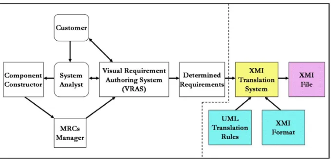
(33) 2). Follow the transiting mapping rules to translate static information and dynamic information into UML/XMI metadata. 3). Follow the XMI format to save the UML/XMI metadata as XMI file.. 3.3 Proposed Translation System Model Figure 22 depicts the proposed translation system model. It is based on visual requirement authoring system. We add four parts shown on the right-hand separated by dashline. These new added parts are used to translate VRAS script that represents the determined requirements. Those un-shadowed diagrams in the Figure 22 had been described in [1]. The following will describe the shadowed parts: XMI Translation System: this system can be considered as a bridge between multimedia visual requirements and UML representation. According to UML translating rules and XMI format, it translates the VRAS script that represents multimedia visual requirements into XMI file that can be used to represent UML notation. UML translating rules: define the translating mapping rules from script content into UML notation. These rules ware discussed in section 3.1.2. XMI Format: the XMI format is defined in the XMI 2.1 specification. There is existing XMI model generated according XMI schema production rules. The XMI model includes XMI element, documentation, and extension. XMI File: It is the target code of the translation system.. Figure 22 The proposed translation system model of this thesis. 23.
(34) The following list the procedure of this translation model from requirements to UML representation through XMI file. Step 1: Use VRAS to construct requirement through MRCs selected and preview prototyping system to make sure the correctness of requirements. System Analyst use VRAS to capture customer’s requirement. Step 2: When existing MRCs are not adequate to describe customer requirements, MRCs Manager uses the Component Constructor to add new MRCs to articulate multimedia visual requirements representation. Step 3: Repeat 1-2 until determined requirements are produced. Step 4: Developers use XMI translation system to generate XMI file to interchange metadata with UML CASE tool. Step 5: Developers use UML CASE tool to represent the UML and generate the framework for specific programming language and documents.. 3.4 Architecture Model Figure 23 illustrates the architecture Model to show the translation system and its relationship with other systems. There are three systems elaborated below: VRAS: Visual requirement authoring system can present multimedia visual requirements to capture user requirement. It also can save those the multimedia visual requirements as text-based script automatically. Translation System: it can extract information from VRAS script and translate them into UML/XMI metadata, and then save as XMI file format. UML CASE TOOL: UML CASE TOOL interchange metadata with translation system through XMI file and represent UML graphic notation.. 24.
(35) Multimedia Visual Requirements Representation. VRAS. Script for MVRR. Translation System. XMI File. UML CASE TOOL. Figure 23 The architecture model. 25. UML Diagram Representation.
(36) Chapter 4 System Design and Implementation This chapter discusses the system design and implementation of the proposed translation system. In the system design part, we describe system architecture, system internal structure, and the design concept of system. In the implementation part, we describe the implement environment, cooperating tool, and user interfaces of the proposed translation system.. 4.1 System Architecture The Model-View-Controller (MVC) design pattern [18] is a good system architecture pattern to split an application into data (model) and user interface (view) concerns, so that the change of the user interface in the future will not affect data handling, and the data can be reorganized without changing the user interface. We adopt the MVC design pattern to construct the proposed translation system in order to decouple relationship between metadata and user interface. Please see Figure 24.. Figure 24 The MVC architecture of translation system. 26.
(37) 4.2 System Structure In section 3.2, we have shown the responsibilities of translation system. We will design relative functional blocks to realize those responsibilities. Figure 25 illustrates functionalities of these cooperated blocks in the system structure. The shadowed blocks are functional block. The un-shadowed blocks are data stored in file or memory. These three functional blocks cooperate to finish translating task from VRAS script representation to XMI script representation.. Figure 25 The structure of translation system Script File: It is a script program representing multimedia visual requirements. VRAS converts multimedia visual requirements into script file. It is also the input of Script Parser. The content of script file describes not only actor static information but also dynamic information including external interaction with user and internal interaction among MRCs. Section 3.1.1 had given the script structure. Script Parser: Use compiler technology (lexical scanner and parser) to build parsertree [8, 20-21]. This research work focus on the implementation of the VRAS script grammar. Parser tree: It includes not only multimedia component properties but also interaction with user or between components. Using compiler technology also let script more easy to maintain and extend.. 27.
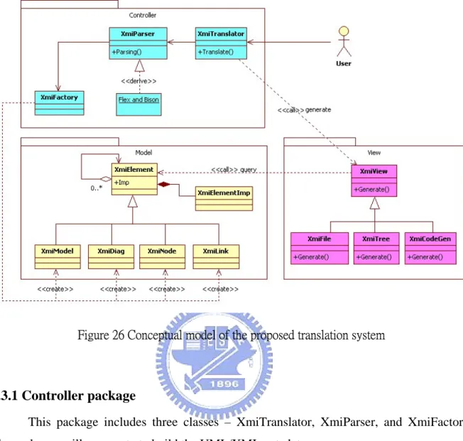
(38) UML Factory: Travel parser tree nodes to extract information of UML elements according to translation rules, and then create UML/XMI element metadata. UML/XMI metadata: It represents the XMI metadata as well as UML. XMI Generator: It converts UML/XMI elements metadata into XMI file according on XMI document format. XMI file: A document format follows the XMI format [6] defined in the XMI specification.. 4.3 System Conceptual model and Detail Design The concept of system design is based on MVC architecture [18] and using several design patterns to construct the whole system. The patterns that we used include factory method pattern, composite pattern, bridge pattern and strategy pattern [11]. Figure 26 illustrates the system conceptual model. This conceptual model includes controller package, model package, and view package. User requests to process translating through user interface (View). Controller accepts the user’s request and starts translating flow: parsing script, walking parser tree, and building the model elements. After model is built, the concrete view queries the content of UML/XMI metadata by itself and represents the result to the user. Next, we will introduce these three packages in detail.. 28.
(39) Figure 26 Conceptual model of the proposed translation system. 4.3.1 Controller package This package includes three classes – XmiTranslator, XmiParser, and XmiFactory. These classes will cooperate to build the UML/XMI metadata. (1) XmiTranslator: It is a coordinator. It coordinates with XmiParser and XmiFacory to build UML/XMI model element (XmiModel, XmiDiag and so on). The figure 27 illustrates the UML model creation flow. Creating empty UML model first, parsing script in the next, and then walking parser tree immediately after parser tree was established. During walking parsing tree, one creates relative diagrams or notations according to translating mapping rules. In order to display the UML notations through UML CASE TOOL, one needs to rearrange the spatial relation of notations within diagram. Finally, adding the profile element to generate UML model.. 29.
(40) Figure 27 UML model creation flow (2) XmiParser XmiParser class is in charge of the parsing job. It creates the parsing tree through lexical scanner and Bison parser and then walks paring tree to build UML model. Figure 28 illustrates the process flow. Lexical scanner groups characters into tokens according to lex regular expression. Bison parser gets tokens through lexical scanner and establishes parser tree using yacc grammar rules. After parser tree is established, XmiParser walks parser tree nodes, and then generate XMI/UML diagram through XMIFactory according to translating mapping rules.. Figure 28 The process of building VRAS parser tree and generate target UML diagrams. 30.
(41) The major lexical specification program and yacc specification program are listed below. Lexical Scanner – This thesis adopt Flex lexical scanner to process token analyze [20]. Here is the lex regular expression used to analyze the token. The following is the partial regular expression file including regular expressions and toke matching rules // regular expressions alpha [a-zA-Z_] alphanum [a-zA-Z_0-9] char \'([^'\n]|\\[ntbrf'\n]|\\0[0-7]{0,2})+\' string \"([^"\n]|\\["\n])*\" unsignedint [0-9]+ …. // toke matching rules character: {char} string: {string} Indent: {alpha}{alphanum}* Integer: {unsignedint}. Grammar Parser – This thesis adopt Bison-parser to parse grammar [21]. Here is the yacc grammar rule used to parsing script. The following is the partial grammar rules. … 11 Cast_List: Cast_Block 12 | Cast_List Cast_Block 13 Cast_Block: LBRACK CAST RBRACK Cast_Type CAST_BEGIN Expression_List CAST_END 14 Cast_Type: MCAnim 15 | MCText 16 | MCMovie 17 | MCSound 18 | MCGroup ……. (3) XmiFactory XmiFactory class is in charge to produce UML notations. It provides several service functions to create various UML notations. XmiParser builds the UML models through XmiFactory class. We adopt factory method pattern [11] to design XmiFactory class. Creating UML notations inside a class with a factory method is always more flexible than creating notations directly.. 31.
(42) 4.3.2 Model package Model package represents UML/XMI metadata. Here we adopt composite pattern [11] and bridge pattern [11] to design model package. We use composite pattern to compose UML notations into tree structure to represent part-whole hierarchies and use bridge pattern to decouple an abstraction (metadata independent on display) from its implementation (metadata dependent on display). There is a root class named XmiElement in the model group. This class plays a role as container to record its children elements and its attributes. All of UML notations (e.g. class, state, lifeline and so on) would be created through XmiFactory class. During creation, these notations are separated into several XMI elements in advance. Figure 29 illustrates an example of UML class notation separated into three XMI elements. A class named Example has one attribute and one operation. The name of attribute is “abc” and the name of operation is “func”. Represent this class by using XMI need three elements totally. There are “Example” element including isAbstract attribute (attribute value is false), “abc” element including visibility (attribute value is public) and “func” element including visibility (attribute value is public) three XMI elements.. Figure 29 An example of UML class notation represented by three XMI elements. All of UML notations supported in this design/implantation would inherit from XmiElement and be composed of several XMI elements. Figure 30 lists the hierarchy of UML/XMI model element that supported in this research work. The first layer is root (XmiElement). The second layer is abstract layer for model, diagram, node, and link. The third layer is dependent on notations within diagram. Others are UML notations supported currently.. 32.
(43) Figure 30 The hierarchy of UML/XMI model elements. 4.3.3 View package In the view package, the design concept is based on strategy pattern [11]. There are an abstract view and three concrete views: XMI file view, XMI tree view, and Code Framework view. None of concrete views would affect any model element. Each concrete view queries data that it is interested from model elements and represents a specific form for user. The following describes three forms supported in the research work.. (1) XmiFile XMIFile class represents UML/XMI metadata by file format to interchange metadata with UML CASE TOOL. Figure 31 illustrates the flow of XMI file representation. XMIFile class query the UML/XMI metadata and saves as XMI file according to XMI format. Those UML/XMI metadata were translated from VRAS script by controller package. After XMI file is saved, users can use UML CASE TOOL to load XMI file and represent UML diagrams.. 33.
(44) XmiFactory. XMIParser VRAS Script. load. Parsing. Walk Tree. Translation Rules. build. UML/XMI metadata. query XmiFile XMI File. save as. XMI Format. load UML Diagrams. display. UML CASE TOOL. Figure 31 The XMI file representation flow. Figure 32 shows the partial XMI file that is outputted by XMIFile class. Line 1 shows the xml version and the encoding format, which are used in XMI file. Line 2 shows the uml model information. The information include “xmi version”, “xmi schema version”, and so on. Lines 3-5 show the tagged value of project type is “UML2Project”. Line 11 represents a class named “TCast” and its Universally Unique Identifier (UUID) [6] - “c8966e02-a341-407f-99ff”. Lines 15-21 represent a class named “TMCBtn”. This class includes “Play” operation (line 17) and “iActor” attribute (line 19). Line 20 represents the generalization relationship between “TMCBtn” class and “TCast” class through the special UUID - “c8966e02-a341-407f-99ff”. Line 24 is the end tag of “uml:model”.. 34.
(45) Figure 32 The partial XMI file outputted by XMIFile class (2) XmiTree XMITree class represents UML/XMI metadata by tree structure. Figure 33 illustrates an example of XMI tree that is generated by XMITree class. There are five types of node used totally - X: XMI, R: Root, E: Element, A: Attribute name, V: attribute value. Each XMI node includes its children nodes and attributes. The first node of tree is XMI file. The second node is model (Root). In this example, the “uml:Model” is composed of five attributes and several elements. Each attribute has its value (e.g. the value of "xmi:version" attribute is "2.1"). 35.
(46) Figure 33 An example of by XMI tree representation. (3) XmiCodeGen Figure 34 shows the relationship between UML model, XMI and code framework. Most UML CASE TOOL can save UML model created by user as XMI file and reload XMI file to represent UML model. Therefore, XMI can be considered as equivalent internal structure of UML model. The code framework can be generated from UML model by UML CASE Tool. The code framework also can be derived from XMI directly. XmiCodeGen class is in charge of code framework generation from UML/XMI metadata.. 36.
(47) UML Model. Equivalent to. Generate to. XMI. Derived from Code Framework. Figure 34 The relationship between UML model, XMI and code framework. The XmiCodeGen class queries the class information from UML/XMI metadata, and then output code framework. Figure 35 illustrates a flow of code framework representation. The XmiParser class cooperates with XmiFactory class to translate from VRAS script file into UML/XMI metadata. After UML/XMI metadata are established, XmiCodeGen class queries correlative information such as class and its operations from UML/XMI metadata, then load predefined template files into internal buffer, and then inserts these information collected previously into memory buffer. Finally, XmiCodeGen class saves the content of memory buffer to generate project file, makefile, and code framework. Both of project file and makefile are for BCB5 integrated development environment (IDE) only. The sample code includes scenes and multimedia actors’ creation, scene branch control, and so on. Developer can generate code framework through UML CASE tool and then reconstruct the target system referring to these sample code rapidly.. 37.
(48) XmiFactory. XMIParser VRAS Script. load. Parsing. Walk Tree. Translation Rules. build. UML/XMI metadata. query XmiCodeGen generate. Project file Makefile C++ file H file. Code Generate. Collect Information. load Template files for code gen.. open. BCB5 IDE / Makefile. build. Sample Program. Figure 35 The sample code representation flow. 4.4 Related implementation issues 4.4.1 Development environment, cooperating tools, and limitation We summarize the related implementation part of this research work in the following: z. This translation system is implemented by C++ language. We use BCB5 IDE [17] to construct user interface.. z. The script file used for the input of this translation system is VRAS script file implemented by the Software Engineering Laboratory of NCTU [23]. The grammar definition file and regular expression used in this thesis depended on this script.. z. Use Flex as scanner generator [20] and use Bison (GUN parser generator) [21] to establish abstract syntax tree.. 38.
(49) z. Due to the XMI extension elements associating display information for TruFun UML CASE TOOL [16], the output XMI file of translation system might not be displayed on other UML CASE TOOL.. z. The code framework generation of translation system is C++ program language. The project file and makefile are for BCB5 IDE only, and the code output path is fixed in the “project file\output\code”. 4.4.2 User Interface (UI) introduction This translation system has two major functions. One is generating XMI file; the other is generating code framework. Figure 36 shows the user interface for XMI file generation.. (2). (1). (3) (4). (5). (6). Figure 36 The UI of XMI File generation The labels on the figure are: 1). Translation button: it is used to start translating from VRAS script to XMI file. 2). XMI Tree window: it represents the XMI metadata by tree structure. 3). XMI Content window: it represents the XMI metadata by text. 4). Save Context button: it is used to save XMI content as file. 5). Exit button: it is used to exit program. 39.
(50) 6). Debug window: it shows the log produced during translating. Figure 37 shows the user interface for code generation.. (1) (5) (2) (6) (3). (4). Figure 37 The UI of Sample code generation The labels on the figure are: 1). Class list window: it lists all of classes in the XMI metadata. 2). Operation list window: it lists the operations of class selected in the class list window. 3). Class Header preview window: it is used to preview the header content of class selected in the class list window. 4). Class Source preview window: it is used to preview the source content of class selected in the class list window. 5). Operation preview window: it is used to preview the content of operation selected in the operation list window. 6). Generate button: it is used to generate sample code.. 40.
(51) Chapter 5 Demonstration and Application Examples In this chapter, we use an example to demonstrate how to translate from multimedia visual requirement representation into UML representation and to show how to verify UML diagram correctness by step.. 5.1 Demonstrating procedure Figure 38 illustrates the demonstrating procedures: 1. VRAS tool [3, 15] authors multimedia visual requirements representation and generates its corresponding script program. VRAS Tool to construct user requirements using Multimedia Reused Components (MRCs) [1]. VRAS Tool will output a visual requirements scripted by EBook Project (EBP) file format and several EBook Script (EBS) files format. 2. Generate XMI file through XMI translation system based on the generated EBP and EBS scripts. The translation system will automatically translate from EBP and EBS scripts into UML/XMI metadata and then output a XMI file. 3. Open TrunFun UML CASE tool [16] and then load the XMI file to represent UML diagrams. 4. Generate sample code through XMI to support reconstruction of the multimedia visual requirement representation. 5. Verification is for represented UML diagram in the step 3. We generate source code framework through UML CASE tool and then fill in related code for the interface actions of the target.. 41.
(52) start Multimedia Visual Requirement. Representation. VRAS Tool. Scripts for MVRR. Translation System. Sample Code Representation. XMI File Representation. BCB5 IDE /. TruFun UML. makefile. CASE TOOL. Sample Program. UML Diagram Representation. Figure 38 The demonstrating procedure. 5.2 Example - A video player UI application system 5.2.1 Multimedia Visual requirements representation by VRAS tool We use a video player UI application system as example to describe the applicability. At first, we construct the video player UI application system. Appendix A describes the details of how the video player UI application construction through VRAS tool. Figure 39 shows the multimedia visual requirements representation for video player UI application system. There are two UIs (or scenes) in this system.. 42.
數據
![Figure 6 Reducing communication complexities among applications through XMI [9] XMI provides a basis for the development of XMI schema](https://thumb-ap.123doks.com/thumbv2/9libinfo/8444617.182093/18.892.127.803.419.872/figure-reducing-communication-complexities-applications-provides-development-schema.webp)
![Figure 11 General connective relations among scenes [1] Scene 1 Scene 3Scene 4Scene 5 Scene 2Scene 1 Scene 3Scene 2 Scene 1 (a) List (b) Graph (c) Tree Scene 1 … Story SceneActorActorActor (MRC) ScenarioScenarioScenario](https://thumb-ap.123doks.com/thumbv2/9libinfo/8444617.182093/23.892.143.794.550.967/figure-general-connective-relations-scene-scene-sceneactoractoractor-scenarioscenarioscenario.webp)
+7
相關文件
² Stable kernel in a goals hierarchy is used as a basis for establishing the architecture; Goals are organized to form several alternatives based on the types of goals and
The first case occurs when #1 is the second candidate after the sub- ordinate player’s rejection point and the best applicant before the subor- dinate player’s rejection point is
One of the main results is the bound on the vanishing order of a nontrivial solution u satisfying the Stokes system, which is a quantitative version of the strong unique
• If there are many challenges and few supports, the text is probably best for storytelling or reading aloud.. • If there are more challenges than supports, the text is probably
Researches of game algorithms from earlier two-player games and perfect information games extend to multi-player games and imperfect information games3. There are many kinds of
For example, there are the procedures of “Mazu’s establishment of a monastery” and the standards of “Baizhang’s introduction of pure regulations.” These were established to
Microphone and 600 ohm line conduits shall be mechanically and electrically connected to receptacle boxes and electrically grounded to the audio system ground point.. Lines in
溫度轉換 自行設計 溫度轉換 自行設計 統計程式 簡單 簡單 統計程式.
