國
立
交
通
大
學
網路工程研究所
碩
士
論
文
一個支援 IEEE 802.16e 輪詢的適應性
頻寬需求機制
An adaptive bandwidth request scheme for IEEE 802.16e
polling services
研 究 生:劉政岳
指導教授:陳耀宗 教授
一個支援 IEEE 802.16e 輪詢的適應性頻寬需求機制
An adaptive bandwidth request scheme
for IEEE 802.16e polling services
研 究 生:劉政岳 Student:Cheng-Yueh Liu
指導教授:陳耀宗 Advisor:Yaw-Chung Chen
國 立 交 通 大 學
網 路 工 程 研 究 所
碩 士 論 文
A ThesisSubmitted to Institute of Network Engineering College of Computer Science
National Chiao Tung University in partial Fulfillment of the Requirements
for the Degree of Master
in
Computer Science
June 2007
Hsinchu, Taiwan, Republic of China
一個支援 IEEE 802.16e 輪詢的適應性頻寬需求機制
研究生 : 劉政岳 指導教授 : 陳耀宗
國立交通大學網路工程研究所
摘 要
隨著無線網路的逐漸普及,為了能夠有大範圍、高頻寬傳輸效能且達到“最後一 哩"目標的 IEEE 802.16 協定因而產生。IEEE 802.16(WiMAX)還是個開發中的技術,所 以尚有許多空間值得改進及討論,我們論文的重點是針對服務品質來加以研究。 在 IEEE 802.16 的機制中,在傳輸各種資料前,都需要用戶端傳送頻寬需求給基地 台,當頻寬不足以讓各個用戶端都用單一輪詢的方式做頻寬需求時,基地台會讓群組用 戶端使用多點輪詢和廣播輪詢的方式競爭傳輸頻寬需求的時槽。802.16e 提出增強的即 時輪詢服務(ertPS)是為了服務靜音壓縮的 IP 網路語音傳輸技術(VoIP),這種傳輸技術 有時間上的要求,延遲要低才能達到較好的效能。 為了降低碰撞產生的延遲,我們提出一種方法讓增強的即時輪詢服務的資料流透過 不用競爭的區段去取得頻寬傳輸的時槽,且同時也保有原本競爭的方法以確保能夠在一 定時間內傳輸頻寬需求,達到減少延遲、增加流通量的目標。最後我們模擬出來的結果, 在用戶端逐漸增加的情況下,增強的即時輪詢服務的需求頻寬延遲可以保持較佳的數 值,且平均流通量也有較好的輸出值。
An adaptive bandwidth request scheme
for 802.16e polling services
Student : Cheng-Yueh Liu Advisor : Yaw-Chung Chen
Institute of Network Engineering
National Chiao Tung University
Abstract
Due to the population of wireless networks, IEEE 802.16 protocol was developed in
order to achieve large coverage, high bandwidth and last-mile access. IEEE 802.16, also
called WiMAX, is still a technology under developing, and there are various issues that are
worthy of investigation. This thesis focused on the study of QoS over WiMAX. Before
transmitting various kinds of packet based on the scheme of 802.16, subscriber stations (SS)
must transmit a bandwidth request message to the base station (BS). When bandwidth is not
sufficient to allow each SS using unicast polling to get bandwidth, BS will form a group of
stations that utilize multicast polling and broadcast polling to contend the slots of transmitting
bandwidth request. Extended real-time polling service which serves the VoIP flows with
silence suppression is proposed in 802.16e. Since this technology has certain delay time
requirement, and the lower delay will achieve higher QoS performance.
In order to decrease the delay which was caused by collisions, we proposed a scheme
that could utilize contention-free period to get slots for bandwidth request, they also save the
original contention period to achieve our goal that decreases delay and increases average
throughput. The simulation results show that our method features lower delay time and better
performance of ertPS flows due to the increasing number of stations.
Acknowledgement
First of all, I would like to express my sincere to the Prof. Yaw-Chung Chen for
processing this thesis and giving me some practical suggestions. He directed me with
appropriate way and inspired me so much. I also appreciate my family for their
encouragement and support. Besides, I have to thank that my laboratory-mates Cheng-Yuan
He, Zhen-Hua Shi, and Juan-Yong Lin. They gave me some useful comments. We discussed
QoS over wireless, admission control, WiMAX scheme and some related issues for lots of
hours. Also, I would like to express my thanks to all members in multimedia communication
laboratory, for their assistances and cheers. Finally, I would like to thank my dear friend
Hsiao-Wei Chuang and my teachers Hsuan-E Hsieh, Hsueh-Ying Chung, who kept pushing
Table of Contents
摘 要 ……….………...i
Abstract ………...……….……….ii
Acknowledgment ……….iii
List of Figures ………...………….………..vi
List of Tables ……….………..vii
Chapter 1 Introduction ………...………...1
Chapter 2 Background ………...………5
2.1 Review of IEEE 802.16 MAC …….……….………...5
2.1.1 Scheduling services ……….5
Unsolicited Grant Service (UGS) …...……….………..6
Real-time Polling Service (rtPS) …..……….7
Non-real-time Polling Service (nrtPS) ……….………...7
Best Effort Service (BE) ……….……….7
Extended real-time Polling service (ertPS) …...…………8
2.1.2 Bandwidth allocation and request mechanisms ………..8
Requests ……….……….………...9
Polling ……….………..9
2.2 MAC support of PHY ……….………15
2.2.1 Frequency Division Duplex (FDD) …..…...………15
2.2.1 Time Division Duplex (TDD) ….…...………..16
2.3 Related Works ……….19
Chapter 3 Proposed Approaches ……….21
3.1 Main Scheme ……….………..21
3.2 Contention-free period definition ……….……….24
3.3 Policy decision procedure ……….………..26
3.4 Mathematical analysis ………...………...29
3.4.1 Numerical analysis of the original scheme ………...………..29
3.4.2 Numerical analysis of proposed scheme ……….…………32
3.4.2.1 Analysis of nrtPS and BE flows ………....………...33
3.4.2.2 Analysis of ertPS flows ………...……….34
3.4.2.3 Performance comparison ……….36
3.5 Summary ……….……….38
Chapter 4 Simulation and Numerical Results ………...…...………39
4.1 Simulation Environment ………....………39
4.2 Simulation Results ……….………..40
4.2.2 Throughput ……….………..43 Chapter 5 Conclusion ………...48 References ………...50
List of Figures
Figure 1-1 IEEE 802.16 PMP mode ………...……….6
Figure 2.1 Unicast Polling ………...………..10
Figure 2.2 Additional BW allocation in unicast polling ………..…..………..………..11
Figure 2.3 Unicast Polling BW Request ………...……….11
Figure 2.4 Unicast Polling BW allocation for data ………12
Figure 2.5 Multicast and Broadcast Polling ………13
Figure 2.6 Multicast or Broadcast Polling BW allocation for BR ………….………14
Figure 2.7 Multicast or Broadcast Polling BW Request ………...……….14
Figure 2.8 Multicast or Broadcast Polling BW allocation for data ………...……….15
Figure 2.9 Example of FDD bandwidth allocation ………...……….16
Figure 2.10 TDD frame structure ...………...………17
Figure 2.11 OFDMA frame structure ………...………..19
Figure 3.1 Mapping OFDMA slots to subchannels and symbols in the uplink …….………22
Figure 3.2 Slots allocation of original scheme ………..………23
Figure 3.3 Slots allocation of proposed scheme ………...……….24
Figure 3.4 Slots allocation example of proposed scheme ……….……….26
Figure 3.5 SS decision flow chart ..……….……..……….27
Figure 3.6 BS decision flow chart .………...……….28
Figure 3.7 Different backoff situations ………..………32
Figure 3.8 Comparisons with two schemes ………...………33
Figure 3.9 Theoretical analysis of delay comparison 1 ……….37
Figure 3.10 Theoretical analysis of delay comparison 2 ………...37
Figure 4.1 Simulation configuration ………...………..39
Figure 4.2 Simulation result of bandwidth request delay 1 ………...………41
Figure 4.3 Simulation result of bandwidth request delay 2 ………...………42
Figure 4.4 Simulation result of bandwidth request delay 3 ………43
Figure 4.5 Comparison of two different bandwidth allocations ………..………..44
Figure 4.6 ErtPS and BE throughputs in two different schemes ………...………45
Figure 4.7 ErtPS throughputs in two different schemes (25 stations) ………...………46
List of Tables
Table 2.1 Scheduling services and usage rules ………...……….6
Table 2.2 Sample UL-MAP with multicast and broadcast IE ………12
Table 2.3 Theoretical performance comparison ……….36
Table 4.1 Simulation result of bandwidth request delay 1 ………...………..41
Table 4.2 Simulation result of bandwidth request delay 2 ………...………..42
Chapter 1 Introduction
During recent years, the increasing demands for high-speed Internet access and
multimedia services in the residential and small office sectors have expected the development
of last-mile access technologies, especially through wireless.
In the mid-1990’s, various groups began to promote “last-mile” fixed wireless access
solutions, they tried to achieve some goals. First, to provide the capacity and reliability of
wireline but with the flexibility and ease of deployment of wireless. Second, to provide a
hierarchical system for corporate or institutional backhaul / distribution networks. Third, to
break the monopolies of incumbent carriers.
In 2001, the IEEE 802.16 standard for BWA (Broadband Wireless Access) systems
which operate in the 10-66 GHz range was released. Although the single carrier modulation
during 10-66 GHz features 30 miles transmission radius and 70Mbps transmission rate, but
the Line-of-Sight (LOS) limitation is still a problem. Until January 2003, 802.16a was
published. It does not only include new PHY layer specification and enhanced MAC
functionality, but also add 2-11 GHz in spectrum. So the signal can be used in
Non-Line-of-Sight (NLOS) environment and the single antenna can also serve multiple
stations. Several years later, IEEE 802.16a / b / c and various updates were incorporated into
IEEE 802.16-2004 [1].
The Worldwide Interoperability for Microwave Access (WiMAX) technology based on
the IEEE 802.16-2004 Air Interface Standard is rapidly proving itself as a technology that will
play a key role in fixed broadband wireless metropolitan area networks. The first certification
lab, established at Cetecom Labs in Malaga, Spain is fully operational and lots of trials are
underway in Europe, Asia, Africa and North and South America [21]. Unquestionably, Fixed
cost-effective fixed wireless alternative to cable and DSL services. In December, 2005 the
IEEE ratified the 802.16e amendment to the 802.16 standard [2]. This amendment adds the
features and attributes to the standard that is necessary to support mobility. The WiMAX
Forum is now defining system performance and certification profiles based on the IEEE
802.16e Mobile Amendment. Beyond the air interface, the WiMAX Forum is defining the
network architecture necessary for implementing an end-to-end Mobile WiMAX network. [3]
A network that utilizes a shared medium shall provide an efficient sharing mechanism.
The WiMAX architecture depends on point to multipoint (PMP) and Mesh networks to
achieve medium sharing. The medium means the space which can propagate the radio waves.
The PMP mode is illustrated in Figure 1.1.
Figure 1.1 IEEE 802.16 PMP mode [22].
WiMAX provides fixed, nomadic, portable, and mobile wireless broadband
connectivity without the need for line-of-sight with a base station. In a typical cell radius
deployment of three to ten kilometers, WiMAX Forum Certified systems can be expected to
deliver capacity of up to 40 Mbps per channel, for fixed and portable access applications. This
thousands of residences with DSL speed connectivity. Mobile network deployments are
expected to provide up to 15 Mbps of capacity within a typical cell radius deployment of up
to three kilometers. It is expected that WiMAX technology will be incorporated in notebook
computers and PDAs by 2007, allowing for urban areas and cities to connect with each other
for portable outdoor broadband wireless access.
We know that the WiMAX has been analyzed in lots of countries and organizations, such
as Nokia and Intel will cooperate to develop the WiMAX technologies. South Korea’s
electronics and telecommunication industry spearheaded by Samsung Electronics and ETRI
has developed its own standard, WiBro. In late 2004, Intel and LG Electronics have agreed on
interoperability between WiBro and WiMAX. The telephone and telegraph office in Taiwan
also work hard for opening the spectrum up.
We may ask whether one size of WiMAX transmission scope really fit all conditions.
Different applications have different requirements and constraints for spectrum and
performance. So to allow options within a consistent framework is a suitable idea, because
factories can choose serviceable standard profiles from limited set of standard profiles.
IEEE 802.16 seeks to provide the required features to serve users. One main element of
WiMAX technology is the interoperability of WiMAX equipment that can integrate much
wireless stations or products and let them work together. A common platform could achieve
lower cost. Fixed wireless equipments will be able to use the same modem chipset used in
personal computers (PCs) and PDAs. For short distance, the equipments will be similar to a
cable or DSL and the base stations will be able to use the same chipsets developed for
low-cost WiMAX access points. So they also provide lower cost equipments which support
WiMAX and original functionality.
The technology behind WiMAX has been optimized to provide Non-Line-of-Sight
(NLOS) coverage. Non-Line-Of-Sight advantages are coverage of wider area and better
modulation schemes with the ability to deliver higher bandwidth efficiency and therefore
higher data throughput, with more than 1 Mbps downstream and even much higher data rates,
even in NLOS with multipath conditions. Adaptive Modulation also increases link reliability
for carrier-class operation and the possibility to keep 64 QAM modulation at wider distance
extend full capacity over longer distances. Optimized handover also ensures the time being
less than 50ms.
QoS (Quality-of-Service) is an important issue in wireless network especially for those
service flows belonging to voice and video. IEEE 802.16 has already specified complete
construction, including how they achieve QoS requirement. In 802.16, there are five types of
scheduling services specified for different traffic models, i.e. Unsolicited Grant Service
(UGS), real-time Polling Services (rtPS), non-real-time Polling Service (nrtPS), Best Effort
(BE), and Extended real-time Polling Service (ertPS) which was published in IEEE 802.16e.
Among the five service flows, the QoS support in UGS, rtPS, and ertPS is necessary. Here we
briefly introduce what problem may occur in 802.16 and how can we solve it.
Before the uplink data transmission in IEEE 802.16 PMP mode, the subscriber station
must send their bandwidth request first to base station and let it know how much bandwidth is
required. When the whole bandwidth isn’t enough for all stations to send individual
bandwidth request, the service flows belonging to ertPS, nrtPS, and BE have to count on
contention to send their requests. There is certain collision probability during contention
period and that would cause the request delay for the ertPS flows. When the request was
delayed, the station couldn’t get proper bandwidth and as a request its QoS will degrade. So
how to solve the collision problem will be discussed in this thesis.
The rest of this thesis is organized as follows. Chapter 2 provides an overview of the
802.16 system. Chapter 3 describes the detailed problem in 802.16 and our proposed scheme
in detail. The numerical analysis and simulation evaluation are presented in Chapter 4.
Chapter 2 Background
In this chapter, we first introduce the 802.16 MAC, including the scheduling services,
bandwidth allocation, request, and polling mechanisms. Regarding the scheduling services,
QoS issues would be discussed in more detail. As we have addressed in Chapter 1, bandwidth
allocation will be based on bandwidth request from each subscriber station (SS). So the
timing of sending request and the probability of successful polling would affect the
transmission efficiency.
Next we briefly review the WiMAX frame architecture and MAC support of PHY.
Several duplexing techniques are supported by MAC protocol. The choice of duplexing
technique may affect certain PHY parameters as well as impact the features that can be
supported. So we will introduce this architecture first, then we will address related works that
have been proposed.
2.1 Review of IEEE 802.16 MAC
2.1.1 Scheduling services
Scheduling services represent the data handling mechanisms supported by the MAC
scheduler for data transport in a connection. Each connection is associated with a single
scheduling service. A scheduling service is determined by a set of QoS parameters about its
behavior. These parameters are managed by using the Dynamic service addition (DSA) and
(UGS), Real-time Polling Service (rtPS), Non-real-time Polling Service (nrtPS), Best Effort
(BE), and extended real-time Polling service (ertPS) are supported in 802.16e.
Uplink request / grant scheduling is performed by the BS with the intent of providing
each SS with bandwidth for uplink transmissions or opportunities to request bandwidth. By
specifying a scheduling service and its associated QoS parameters, the BS scheduler can
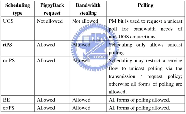
anticipate the throughput and provide polls and/or grants at the appropriate times. Table 2.1
summarizes the scheduling services and the poll / grant options. The following sections define
flow scheduling services for uplink operations.
Scheduling type PiggyBack request Bandwidth stealing Polling
UGS Not allowed Not allowed PM bit is used to request a unicast poll for bandwidth needs of non-UGS connections.
rtPS Allowed Allowed Scheduling only allows unicast polling.
nrtPS Allowed Allowed Scheduling may restrict a service flow to unicast polling via the transmission / request policy; otherwise all forms of polling are allowed.
BE Allowed Allowed All forms of polling allowed. ertPS Allowed Allowed All forms of polling allowed.
Table 2.1 Scheduling services and usage rules
Unsolicited Grant Service (UGS)
The UGS is designed to support real-time service flows that generate fixed-size data
packets on a periodic basis, such as T1/E1 and Voice over IP without silence suppression.
The services privide fixed-size grants on a real-time periodic interval which eliminate the
real-time requirement.
The BS should provide Data Grant Burst information elements (IEs) to the SS at periodic
intervals based on the Maximum Sustained Traffic Rate of the service flow. The size of these
grants should be sufficient to hold the fixed-length data associated with the service flow. In
order for this service to work correctly, the Request / Transmission Policy must be set so that
the SS is prohibited from using any contention request opportunities for this connection.
Real-time Polling Service (rtPS)
The rtPS is designed to support real-time service flows that generate variable size data
packets on a periodic basis, such as moving pictures experts group (MPEG) video.
This service provides real-time, periodic, and unicast request opportunities which
conform to the flow’s real-time requirement and allow the SS to specify the size of the desired
grant. This service requires more request overhead than UGS, but supports variable grant
sizes for optimum data transport efficiency. The BS should provide periodic unicast request
opportunities, and it may issue unicast request opportunities even if prior requests are
currently unfulfilled. SSs which are belonging to this category should use only unicast request
opportunities in order to obtain uplink transmission opportunities.
Non-real-time Polling Service (nrtPS)
The nrtPS is designed to support delay-tolerant data streams consisting of variable-sized
data packets for which a minimum data rate is required, for example, FTP may use nrtPS.
The service provides unicast polls on a regular interval, which assures that the service
flow receives request opportunities even during network congestion. The BS polls nrtPS
flows on an interval. The BS should provide timely unicast request opportunities.
The BE service is designed to support data streams without minimum service level
required, therefore it may be handled on a channel-free interval, such as web browsing and
E-mail. The purpose of the BE service is to provide efficient service for best effort traffic and
use contention period to get transmission opportunities.
Extended real-time Polling service (ertPS)
The Extended rtPS is designed to support real-time service flows that generate variable
size data packets on a periodic basis, such as Voice over IP services with silence suppression.
It is a scheduling mechanism which builds up the efficiency of both UGS and rtPS. The
BS should provide unicast grants in an unsolicited service flow like in UGS to save the
latency of a bandwidth request. However, the UGS allocations are fixed size and ertPS
allocations are dynamic. The BS may provide periodic UL allocations that may be used for
requesting the bandwidth as well as for data transfer. By default, size of allocations
corresponds to the current value of Maximum Sustained Traffic Rate of the connection.
The BS should not change the size of UL allocations until receiving another bandwidth
change request from the MS. When the bandwidth request size is set to zero, the BS may only
provide allocations for bandwidth request header or no allocations at all. In case that no
unicast bandwidth request opportunities are available, the MS may use contention request
opportunities for that connection to inform the BS regarding that it has data to send.
2.1.2 Bandwidth allocation and request mechanisms
Increasing (or decreasing) bandwidth requirements is necessary for all services except
incompressible constant bit rate UGS connections. The bandwidth allocations of
incompressible UGS connections do not change between connection periods. The
decrease depending on the traffic condition. When an SS needs to ask for bandwidth on a
connection with its scheduling service, it sends a message to the BS containing the immediate
requirements. QoS for the connection was established at connection establishment and is
looked up by the BS.
Requests
Requests refer to the mechanism used by SSs to inform to the BS regarding their need of
uplink bandwidth allocation. A Request may come as a stand-alone bandwidth request header
or it may come as a PiggyBack Request.
The Bandwidth Request message may be transmitted during uplink bandwidth allocation,
except during initial ranging interval. Bandwidth Requests may be incremental or aggregate.
When the BS receives an incremental Bandwidth Request, it adds the quantity of bandwidth
requested to its current bandwidth in the connection. Otherwise, if the BS receives an
aggregate Bandwidth Request, it should replace its assigned bandwidth of the connection with
the quantity of bandwidth requested. The Type field in the bandwidth request header indicates
whether the request is incremental or aggregate. Since Piggybacked Bandwidth Requests do
not have a type field, Piggybacked Bandwidth Requests should be always incremental.
Finally, when the BS receives a Bandwidth Request from any SS, it should make use of
admission control scheme to check whether the request is permitted or not.
Polling
Polling is the process in which the BS allocates bandwidth to SS by sending request.
These allocations may be to an SS or to a group of SSs. The polling should be done on SS
basis. Note that bandwidth is always requested by a CID and it is allocated to an SS.
According to the bandwidth congestion situation, there are three polling types, unicast,
First, we introduce the procedure of unicast polling. When an SS is polled, there is no
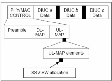
explicit message that can be sent to poll SS. Rather, the BS actively allocate SS slots in
UL-MAP (introduced in section 2.1.3) for sending bandwidth request. UGS connections do
not need to be polled individually, because they need a much efficient way to get bandwidth
unless they set the poll-me (PM) bit in the packet header. Unicast polling could only be used
if the bandwidth is sufficient for polling whole individual SSs.
Figure 2.1 Unicast Polling
As illustrated in Figure 2.1, first the unicast polling procedure should check whether
more BW is available for individual polling or not. If it is not enough, the multicast and
broadcast polling algorithm should be initiated. Then we continue to make some check, for
example, were SSs with expired polling interval? Did unpolled SSs PM bit set? After the
In Figure 2.2, it shows that SS’s polling interval was already expired and BS allocated
the bandwidth to SS. The allocated slots were defined in UL-MAP.
Then, we can realize that SS would transmit bandwidth request in allocated slots, just
like Figure 2.3. It also provides contention period to a group SSs.
Finally, BW allocation algorithm would be used and uplink subframe map would be
changed, as shown in Figure 2.4.
Figure 2.2 Additional BW allocation in unicast polling
Figure 2.4 Unicast Polling BW allocation for data
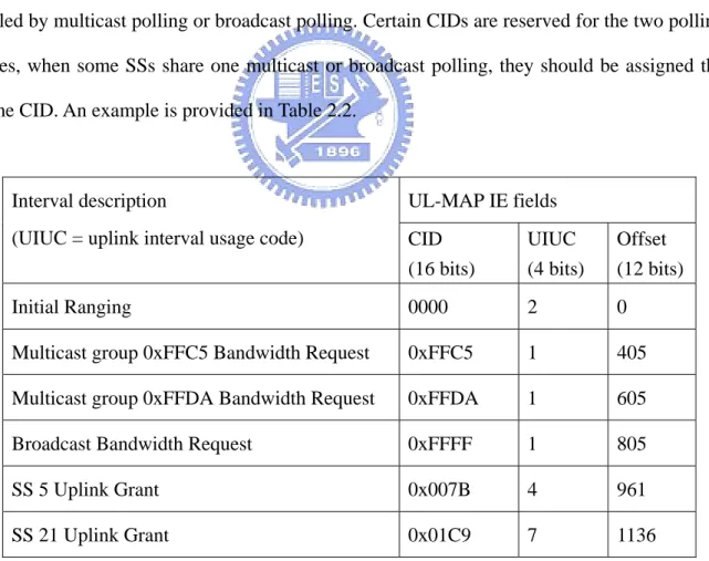
If available bandwidth is insufficient for polling whole individual SS, some SSs may be
polled by multicast polling or broadcast polling. Certain CIDs are reserved for the two polling
types, when some SSs share one multicast or broadcast polling, they should be assigned the
same CID. An example is provided in Table 2.2.
UL-MAP IE fields Interval description
(UIUC = uplink interval usage code) CID (16 bits) UIUC (4 bits) Offset (12 bits) Initial Ranging 0000 2 0
Multicast group 0xFFC5 Bandwidth Request 0xFFC5 1 405
Multicast group 0xFFDA Bandwidth Request 0xFFDA 1 605
Broadcast Bandwidth Request 0xFFFF 1 805
SS 5 Uplink Grant 0x007B 4 961
SS 21 Uplink Grant 0x01C9 7 1136
Table 2.2 Sample UL-MAP with multicast and broadcast IE
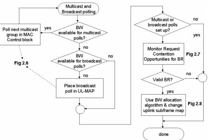
Figure 2.5. Different from individual polling that depends on contention period to select the
slot through which to transmit its bandwidth request. In order to avoid collision, they use
contention resolution algorithm to decrease the collision probability. If no grant has been
received during the specified timeout duration, we could assume that the transmission was
unsuccessful.
Based on Figure 2.5, we could discuss the procedure in more detail. Just like unicast
polling, SS must be allocated the slots first when SS’s polling interval was expired, as shown
in Figure 2.6.
Figure 2.5 Multicast and Broadcast Polling
After the SSs have been allocated a uplink duration, they could participate the contention
period to get the transmission opportunity. If a certain SS has already obtained the slot and
admission control scheme. Otherwise, SSs must wait for backoff time until it gets TXOP. The
BW request message must include the SS ID, connection ID, and the requested bandwidth as
shown in Figure 2.7. Last, the data transmission could be transmitted as illustrated in Figure
2.8.
Figure 2.6 Multicast or Broadcast Polling BW allocation for BR
Figure 2.8 Multicast or Broadcast Polling BW allocation for data
Then, we briefly introduce how the contention resolution algorithm be implemented. The
BS has more flexibility in controlling the contention resolution. The mandatory method of
contention resolution that should be supported is based on a truncated binary exponential
backoff, with the initial backoff window and the maximum backoff window controlled by the
BS. The values are specified as part of the uplink channel descriptor (UCD) message which
represents a power-of-two value. For example, a value of 4 indicates a window between 0 and
15; a value of 10 indicates a window between 0 and 1023.
2.2 MAC support of PHY
In this section, we introduce two major duplexing techniques and frame structure. One of
the duplexing techniques is Frequency Division Duplex (FDD), the other one is Time
Division Duplex (TDD).
FDD is a duplex scheme in which uplink and downlink transmissions use different
frequencies but are typically simultaneous. In an FDD system, the uplink and downlink
channels are separated in different channels, so they can transmit two-way data at the same
time.
Both uplink and downlink transmissions could be used in a fixed duration. It also allows
simultaneous use of full-duplex SSs which can transmit and receive simultaneously and
half-duplex SSs which cannot. If half-duplex scheme is used, an SS can not transmit and
receive data at the same time. Otherwise, both of them could operate simultaneously.
Figure 2.8 is an example which describes the process of an FDD mode.
Figure 2.9 Example of FDD bandwidth allocation
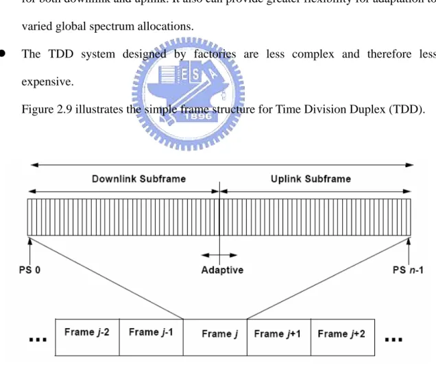
2.2.1 Time Division Duplex (TDD)
In the TDD system, the downlink and uplink transmissions operate at different times but
could share the same frequency. A TDD frame has a fixed duration and contains one downlink
and uplink subframe. The frame is divided into an integer number of slots which make the
layers using a system parameter.
The 802.16e PHY supports TDD, full-duplex FDD, and half-duplex FDD operation,
however the initial release of Mobile WiMAX certification profiles will only include TDD.
With recently releases, FDD profiles will be considered to address specific market. TDD is
the preferred duplexing mode for the following reasons:
z TDD allows adjustment of the downlink and uplink ratio to efficiently support asymmetric two-way traffic. With FDD, downlink and uplink always have fixed and
similar bandwidth.
z Unlike FDD, which requires a pair of channels, TDD only requires a single channel for both downlink and uplink. It also can provide greater flexibility for adaptation to
varied global spectrum allocations.
z The TDD system designed by factories are less complex and therefore less expensive.
Figure 2.9 illustrates the simple frame structure for Time Division Duplex (TDD).
Figure 2.10 TDD frame structure.
Receive transition Gaps (TRG) or Receive / Transmit transition Gaps (RTG) to prevent
downlink and uplink transmission collisions.
The following control information is used to control the system operation in a frame:
z Preamble: The preamble is used for synchronization and is also the first OFDM symbol of a frame.
z Frame Control Head (FCH): The FCH follows the preamble and is used for providing the frame information such as MAP message length, two-way channel
descriptor (UCD and DCD), and usable sub-channels.
z DL-MAP and UL-MAP: The two MAPs provide some control information including DL bursts, UL bursts, and ranging period. The burst configurations,
composed of slots, are always built in the form of rectangles.
z Ranging and Bandwidth Request subchannel: Ranging and Bandwidth Request are always combined to form a signal channel which can simplify the design
complexity. Via the Initiate Ranging IE, the BS specifies an interval in which new
stations may join the network. Ranging period is an interval, equivalent to the
maximum round trip propagation delay plus the transmission time of the RNG-REQ
message, shall be provided in some UL-MAPs to allow new stations to perform
initial ranging. Packets transmitted in this interval shall use the RNG-REQ MAC
Management message. And the transmission process of Bandwidth Request is
similar to Ranging Request.
Figure 2.10 illustrates an example of OFDMA frame structure. A slot in the OFDMA
PHY requires both a time and subchannel dimension and is the minimum possible data
allocation unit. The definition of an OFDMA slot depends on the OFDMA structure, for
example, if uplink and downlink using the adjacent subcarrier permutation, one slot is one
subchannel by one OFDMA symbol.
Figure 2.11 OFDMA frame structure
2.3 Related Works
In our survey, most of those scheduling algorithm were focusing on QoS issues
especially for UGS, rtPS, and ertPS. In [4], the author proposed an simple and efficient
algorithm which calculates each connection allocated slots and controls order of slots to
decrease the jitter. In [5], the proposed scheme adaptively allocates bandwidth in order to
control queue length at a target level so that the requirements for delay and PDU dropping
probability can be met. It also presented an analytical queueing framework to analyze the
proposed scheme. On [6], authors suggest a system model that could consider the voice state
transitions. They use voice activity detector and silence detector to check whether the state is
on or off, then rely on system to calculate the steady-state probability.
Several adaptive schemes were proposed to dynamically allocate resource allocations.
demands and maximize system throughput. In [7], it presented linear programming
relaxations for resource allocation problem and provide optimal allocations for all users. The
method would be based formulations to achieve maximum throughput.
IEEE 802.16e provides ertPS, a new scheduling algorithm for supporting silence
suppression, it has some advantages that not only reduce MAC overhead and access delay of
the rtPS algorithm, but also prevent the uplink resources waste of the UGS algorithm. On [8],
the authors make some analyses to verify the ertPS performance. Based on the simulation
results, the ertPS algorithm indeed has better performance than both UGS and rtPS
algorithms.
Although lots of related scheduling algorithm has been proposed, different environment
should have different requirements. How to achieve the distinct purposes in the whole
Chapter 3 Proposed Approaches
Firstly, we explain the problem that could be found in WiMAX and address our
motivation. In 802.16e, the ertPS was proposed to support real-time service flows that
generate variable size data packets on a periodic basis, such as Voice over IP services with
silence suppression. VoIP uses conventional IP network to provide voice communication
service between end users. It is much cost effective and easier to construct IP networks than
traditional telecommunication networks, and it is also convenient for the users of voice
service, so VoIP market grows up quickly.
Therefore, lots of users try to use handset devices in place of traditional telephones to
make VoIP calls through networks. This means that providing QoS is necessary for VoIP
connections, especially in WLAN. But in WiMAX system, when bandwidth isn’t enough for
unicast polling, ertPS must use multicast polling or broadcast polling to participate contention
with nrtPS or BE. This usually causes collisions during contention period and the bandwidth
request delay could not be guaranteed, and the packets could not be transmitted immediately.
Except the delay, SSs could not get suitable bandwidth (larger or less) and may cause the
bandwidth wasting.
Based on the above observation, we proposed a scheme for providing QoS in WiMAX
environment. The scheme adjusts their transmitting sequence to allow ertPS connections to
have better priority. We will use some mathematic equations to calculate the delay.
3.1 Main Scheme
The bandwidth request must be implemented in uplink subframe, so we will focus our
polling period will not be restricted in specific channel, but based on the frame burst
allocations, they are always built in the form of rectangles, as illustrated in Figure 3.1. So the
multicast polling and broadcast polling should be defined in one or multiple specific channels
to reduce the difficulty of UL-MAP definition. Some factories combine the ranging and
bandwidth request to a specific channel called signal channel. Our simulation will use one
channel for a contention period of multicast polling or broadcast polling.
Figure 3.1 mapping OFDMA slots to subchannels and symbols in the uplink.
For uplink, there are two kinds of permutation to choose from. One is adjacent subcarrier
permutation, in which each slot is one subchannel by one OFDMA symbol; the other one is
symbol. We adopt the adjacent subcarrier permutation to implement our scheme because it is
easier to implement (The permutation in Figures 3.1 is distributed subcarrier permutation).
Figure 3.2 Slots allocation of original scheme
In Figure 3.2, we provide a diagram to illustrate the original multicast or broadcast
polling situation. Each slot is a transmission opportunity, service flows have to contend the
slots if more than one flows want to transmit request at the same slot. If collision occurs,
backoff will be performed to request again.
Our goal is to reduce the collision of ertPS flows. The key idea of our main scheme is to
sacrifice the request contention time of nrtPS and BE connections, because these two service
flows does not have immediate QoS demand. If there are VoIP packets to be sent by ertPS
flows, we assign the first several slots to ertPS connections and the slots could not be
occupied by nrtPS or BE flows.
First the BS must define one period called contention-free (CF) period to ertPS
bandwidth requests so as to avoid contention possibility and increase the success probability.
The CF period does not occupy other bandwidth but divide the original polling contention
period into two periods. The heading slots are integrated into CF period which could be
allocated to ertPS flows only, and the remainding slots keep the original functionality. Both
unicast polling and multicast polling (or broadcast polling). In Figure 3.3, the diagram
illustrates the framework and slots allocation.
Figure 3.3 Slots allocation of proposed scheme
In our scheme, the ertPS flows are guaranteed to have two kinds of transmission
opportunities. If an ertPS flow was allocated a CF period slot, it can transmit the bandwidth
request packet immediately; otherwise, it can participate the contention period with nrtPS
flows and BE flows.
3.2 Contention-free period definition
In order to calculate how many slots in contention period could be allocated to CF period,
first we must figure out the ratio of ertPS flows to all service flows. For example, if there are
20 slots in multicast or broadcast polling contention period, 5 ertPS flows and 20 nrtPS or BE
flows, the ratio is 1 to 4. According to the ratio to allocate the CF slots, the number is 4
(20*5/(5+20)=4).
Each CF slot could only be used by the assigned service flow. For example, if the first
is no request to send. This is the disadvantage of our scheme that has possibility to waste
bandwidth, because the CF slots are allocated in advance. Beside wasting bandwidth, shorten
nrtPS and BE contention period would cause the increasing of their request delay. As
illustrated in Figure 3.3, the situation is clear at a glance. Although our scheme brings these
two disadvantages, it is still worthy to improve the performance of ertPS flows.
Since the transmission range of WiMAX is much larger than that in WiFi, hundreds of
users may utilize the same WiMAX base station at the same time. In general, it is not
sufficient for allocating the CF slots to service flows one by one. The BS is not aware when
the SSs have bandwidth request to send, so we allocate each CF slot to ertPS flow with
random selection for fairness. Although we divide some slots to let ertPS flows transmit
bandwidth request first, the number of CF slots still has its limitation in providing essential
bandwidth for ertPS and BE flows. So we set threshold which is half of the contention period.
The number of CF slots can be obtained as follows:
⎪ ⎪ ⎩ ⎪⎪ ⎨ ⎧ >= × < × × = ) 2 ) _ ( ( 2 ) 2 ) _ ( ( ) _ ( N N ert N C if N N N ert N C if N ert N C CF (1)
Where, CF is the number of allocated slots.
C is the total slots in contention period.
N is the number of whole service flows.
N_ert denotes the number of ertPS flows.
According to Equation (1), if C multiplied by the ratio of N_ert to N is no larger than
half of N, we do the allocation directly; otherwise, it could only get half of N.
Figure 3.4 shows a slots allocation sample of our scheme. We assume that the randomly
selected number is four, so the CF slots are allocated to the ertPS flows whose serial numbers
are from 4 to 8. The slots of 4 and 7 indicate that the stations are transmitting bandwidth
transmission or have no buffered packets to be handled. Other ertPS flows which are not
allocated CF slots could only participate contention period with nrtPS and BE flows.
Figure 3.4 Slots allocation example of proposed scheme
3.3 Policy decision procedure
As illustrated in Figure 3.5, the policy decision of SSs would obey the procedure. One
SS may have more than one service flow and each of them is uncertain. So during the SS
decision procedure, SS will check whether sending bandwidth request is necessary or not,
then determine its service flow type. If the type is ertPS flow and has been allocated CF slot,
it could transmit bandwidth request immediately. Otherwise, they participate in contention, no
matter what kind of service flow it is. When collision occurs, the service flow must wait for
backoff timer to finish, then retry the transmission procedure.
When many service flows were ready to transmit bandwidth request before transmitting
a frame, they always try to occupy the first slot in contention period, this may cause higher
collision probability.
Since each frame or each uplink subframe could have only one signal channel which we
Figure 3.5 SS decision flow chart.
multicast and broadcast polling will be implemented in signal channel, so the first BS must
define which channel to be used. Then BS checks the situation of each SS, because an initial
service flows or a leaving one will cause the allocated CF ratio to redistribute. Finally, BS
relies on the information which was collected in prior steps, and changes uplink subframe
map, as illustrated in Figure 3.6.
Like SS decision flow charts, BS decision flow charts will also operate once in each
uplink subframe.
3.4 Mathematical analysis
The simulation results and performance evaluation are presented in Chapter 4. Before it,
we introduce some mathematical analysis to compare the performance with the original
scheme in the standard. We define that the delay is the time spent until a bandwidth request
message is successfully transmitted, and this information is the most important observations
in our analysis. In order to obtain the delay information, we need to find the count of
retransmissions first, then add the backoff time to get our theoretical delay data.
3.4.1 Numerical analysis of the original scheme
The probability that one bandwidth request message is located in a specific slot is 1/C,
where C is the total number of slots in contention period (according to Equation (1)). This is
based on the assumption that the bandwidth request is uniformly distributed during a
contention period.
We analyze the statistics from the point of view of a specific service flow. The
probability (Pnot_the_same) that no other bandwidth request messages are transmitted in the same slot is given by
1 _ _ 1 1 − ⎟ ⎠ ⎞ ⎜ ⎝ ⎛ − = N same the not C P (2) where, N is the number of total service flows.
According to Equation (2), we could derive the probability (Psuc_slot) that successfully transmit a bandwidth request message in a slot.
C C P N slot suc 1 1 1 1 _ ⎟ × ⎠ ⎞ ⎜ ⎝ ⎛ − = − (3)
Since the contention period size is C slots, the probability (Psuc) of successfully transmitting a bandwidth request message during a contention period can be derived as
follows: 1 1 1 1 1 1 1 − − ⎟ ⎠ ⎞ ⎜ ⎝ ⎛ − = × ⎟ ⎠ ⎞ ⎜ ⎝ ⎛ − = N N suc C C C C P (4) Since we need to find out the retransmission time, utilizing collision probability is
necessary for calculation. We derive the probability (Pcol) of unsuccessfully transmitting a bandwidth request: 1 1 1 1 1 − ⎟ ⎠ ⎞ ⎜ ⎝ ⎛ − − = − = N suc col C P P (5) In our scheme, we have a specific channel called signal channel to implement contention
period. A frame could only have one signal channel, so the collision times in a signal channel
is the same as the collision times in a frame. Using geometric distribution, we can derive the
probability (Psuc(k)) for transmitting a successful bandwidth request in the k-th frame:
(
col)
k col
suc k P P
P ( )= −11− (6) In Equation (6), it means that ransmissions during the first (k-1) frames collided with
other service flows and won’t be successful until the k-th frame.
We use an expected value to represent the average number of retransmission for a
bandwidth request message:
∑
∞ = − ⎟ ⎠ ⎞ ⎜ ⎝ ⎛ − = = 1 1 1 1 1 ) ( k N suc C k kP E (7)where, E is the expected value.
Because we do not know when the bandwidth request will be transmitted successfully,
we set the number of frames from one to infinity and count it accumulately. Finally, we
successful transmission is in 5-th frame. Beside the expected collision count, we also need to
consider backoff delay. So we derive backoff slots first:
window backoff P P P slot Backoff n n slot suc n slot col slot suc min_ _ 2 2 _ 10 1 _ _ _ × × × + =
∑
= (8)where, Backoff_slot means the number of total backoff slots.
n is the power-of-two value.
Psuc_slot is from Equation (3) and Pcol=1-Psul_slot.
min_backoff_window is the minimal backoff window size
The mandatory method of contention resolution that should be supported is based on a
truncated binary exponential backoff, and the initial backoff window and the maximum
backoff window controlled by BS. The values are specified as part of the UCD message and
represent a power-of-two number. We set the initial backoff window from 0 to 15 and the
maximum backoff window from 0 to 1023. So in Equation (8), n is the power-of-two number
that is no larger than 10. Finally, we divide it by 2 to get the average number of backoff slots.
In Equation (8), it accumulates the backoff slots whose n is from 0 to 10. When n is larger
than 10, relative to less than or equal to 10, the values of Psuc_slot and Pcol_slot are very small. So we can ignore it to make the equation simpler.
We can utilize the Backoff_slot to calculate Backoff_delay:
size frame perframe slots slot Backoff delay Backoff * _ _ _ _ = (9) where, we exchange Backoff_slot for Backoff_delay; in other words, they are
different units.
So the unit obtained from Backoff_slot divided by slots_perframe is frame, then we
multiply it with frame_size (5ms in general) to get Backoff_delay with mini-second (ms) as
the unit.
starts. Figure 3.7 illustrates the different backoff situations:
(a)
(b)
Figure 3.7 Different backoff situations
In Figure 3.7 (a), if the collision happened in heading slots of a frame, it shows that the
backoff transmission might be still in the same frame. But in (b), the collision happened in
tailing slots of a frame, it shows that the backoff transmission might wait till the next uplink
subframe. We are unable to predict which one will happen, and it must experience larger
backoff delay in Figure 3.7 (b). Although Equation (9) features some inaccuracy, the value is
not too far from what we think and is acceptable.
Finally, we combine the expected value and backoff delay to get real collision delay:
delay Backoff C F delay Backoff E size Frame Delay N _ 1 1 _ _ 1 + ⎟ ⎠ ⎞ ⎜ ⎝ ⎛ − = + × = − (10)
where, F means the frame size; in general, the value is 5ms.
Because the contention situations in ertPS flows are different from others, we introduce
them in two subsections.
3.4.2.1 Analysis of nrtPS and BE flows
In this section, we introduce the mathematical analysis for nrtPS and BE flows. The
basic idea is the same, because contention period in our proposed scheme reduces some slots.
The probability of successfully transmitting a bandwidth request message during a frame
(or a contention period) is derived as follows:
CF i C P CF i i N suc
∑
= − ⎟ ⎠ ⎞ ⎜ ⎝ ⎛ − − = 1 1 1 (11)where, C is the number of total slots,
CF is the number of slots in contention free period,
N is the number of total service flows (all service flows can participate contention
including ertPS flows),
i means a variable number of service flows that do not participate the contention.
In Figure 3.8, the shaded slots represent real contention periods. It clearly shows us that
our proposed scheme has a smaller successful transmission probability comparing to the
original scheme (Equation (4)). In Equation (11), we do not know how many ertPS flows that
already successfully transmit its bandwidth request, so we utilize a variable value i to control
the situation. We accumulate each probability and divide it by CF to get an average value.
CF i C P P CF i i N suc col
∑
= − ⎟ ⎠ ⎞ ⎜ ⎝ ⎛ − − − = − = 1 1 1 1 1 (12)(
col)
k col suc k P P P ( )= −11− (13) Like that in Section 3.4.1, Equation (12) represents the probability of unsuccessfultransmission of a bandwidth request. Equation (13) means that bandwidth request message
would be transmitted successfully in k-th frame, so the order of Pcol must be k-1.
∑
∞ = = 1 ) ( k suc k kP E (14) delay Backoff E F delay Backoff E size frame Delay= _ × + _ = × + _ (15) The process of deriving Backoff_delay is same as that in Equation (8) and Equation (9),so we do not give details here again. Finally, we also get an expected value and utilize it to
derive the collision delay.
3.4.2.2 Analysis of ertPS flows
In this kind of service flows, two transmission opportunities must be considered; first is
CF transmission opportunity, and the other is contention transmission opportunity.
We list the equations first and explain the definition of parameters, then we discuss the
If (CF<N_ert) CF i C ert N CF C CF ert N CF C CF P CF i i N suc
∑
= − ⎟ ⎠ ⎞ ⎜ ⎝ ⎛ − − × ⎟⎟ ⎠ ⎞ ⎜⎜ ⎝ ⎛ − × + × = 1 1 1 _ 1 _ (16) else CF i C C CF C CF P CF i i N suc∑
= − ⎟ ⎠ ⎞ ⎜ ⎝ ⎛ − − × ⎟ ⎠ ⎞ ⎜ ⎝ ⎛ − + = 1 1 1 1 (17)Where, C is the number of total slots, the value is constant,
CF is the number of contention free period slots, the value will reset when
the ratio of ertPS flows to all service flows is changed.
N is the number of total service flows, the value will be different, if there are
joining or leaving new service flows.
N_ert is the number of ertPS flows.
According to Equation (16) and Equation (17), we could clearly know that we have two
different situations. When CF is less than N_ert, it means that if all ertPS flows have to
transmit bandwidth request messages in the same frame, the number of CF slots is not
sufficient to be allocated for each ertPS flow. When one specific ertPS flow wants to transmit
bandwidth request message during CF period (the probability is CF/C), the transmission does
not collide with other service flows if it has been allocated one CF slot, so the probability
must be multiplied by CF/N_ert. Otherwise, if the service flow is not prepared in CF period or
is not allocated CF slot, it must participate contention and the probability is
1-(CF/C)*(CF/N_ert). According to Equation (11), we could derive the successful probability
in contention period.
If CF is larger than or equal to N_ert, it means that when ertPS flows want to transmit a
others’. In Equation (17), it illustrates this situation.
3.4.2.3 Performance comparison
In this section, we make some comparison of our theoretical analyses. We will list
the expected value of frame, delay, and goodput. E is the expected value of delivered frame,
and we could compare improvement different performance to derive the goodput value,
utilizing Equation (18). Improvement original Delay proposed Delay original Delay _ _ _ − = (18) Proposed scheme Theoretical Service flows Original
scheme ertPS(QoS) Others(non-QoS)
Total number of flows
ertPS Others Delay (ms) Delay (ms) Improvement Delay (ms) 10 5 5 20.03 13.04 34.90% 14.12 15 5 10 30.24 15.25 49.57% 16.39 20 5 15 37.65 18.48 50.92% 20.15 25 5 20 40.17 27.09 32.56% 32.45 30 5 25 42.99 37.38 13.05% 42.17
Table 2.3 Theoretical performance comparison.
As illustrated in Table 2.3, the number of stations is from 10 to 30 and ratio of ertPS
flows to others (including nrtPS and BE flows). When the number of ertPS flows is kept
constant and the number of others is increasing, we could see that proposed ertPS has better
delay result. But by the number of station increases, the delay between original scheme and
proposed scheme will be close because our CF slots allocation is based on the ratio of ertPS
flows. This improvement is still acceptable.
the proposed scheme has better delay performance for ertPS flows
Theoretical analysis (ertPS)
0 10 20 30 40 50 10 15 20 25 30 Stations Delay (ms) Original scheme ertPS_proposed
Figure 3.9 Theoretical analysis of delay comparison 1.
The other services flows would experience higher delay than the original scheme,
because our method is based on reducing the transmission opportunity of QoS-free service
flows, as illustrated in Figure 3.10.
The number of service flows in our theoretical analyses is from 10 to 30, and the real
simulation could not achieve the assumption. It only support no larger than 30 service flows.
This problem would be discussed in Chapter 4, we skip it here.
Theoretical analysis 0 10 20 30 40 50 60 10 15 20 25 30 Stations Delay (ms) Original scheme ertPS_proposed BE_proposed
3.5 Summary
In this chapter, we proposed a scheme that decreases the delay of ertPS flows. Because
ertPS flows are designed to support VoIP with silence suppression, it is necessary to guarantee
their QoS requirement.
The delay of ertPS flows is caused by collisions in contention period. In our scheme, we
divide the period into two periods; one is contention-free (CF) period, the other is shorten
contention period. CF period could only be allocated to ertPS slots, and the shorten contention
period could be participated by all kinds of service flows. So this scheme could achieve our
goal that allows the bandwidth request messages of ertPS flows to avoid collisions. Then we
proposed mathematical equations to compare the performance between the original scheme
and the proposed scheme. Although our scheme may increase the delay in nrtPS and BE flows,
Chapter 4 Simulation and Numerical Results
4.1 Simulation Environment
In addition to demonstrating the performance of our proposed scheme, we use NS-2
(version 2.29) tool [19] with WiMAX PMP module [20] which is originally designed and
developed by Networks & Distributed Systems Laboratory (NDSL) members in Chang Gung
University, Taiwan.
To simplify the simulation, we neglect the sevice flows (UGS and rtPS) that do not use
multicast polling or broadcast polling to participate contention, and one station corresponds to
one service flow. Our network topology of the simulation is shown in Figure 4.1 and we focus
our simulation in the area which can be controlled by one BS.
Each wireless station either runs bidirectional VoIP traffic with silence suppression or BE
traffic which may be an application program such as E-mail or web browsing. VoIP traffic
supporting silence suppression, with format of G.729 codec, 160 bytes payload and 20ms
intervals are used as real-time traffic. G.729 codec could compress 64kbit/s data into 6.4kbit/s
to 11.8kbit/s. Other traffics with 512 to 1024 bytes payload are used to simulate the best effort
traffic (web browsing or E-mail).
4.2 Simulation Results
Before the simulations, we explain a problem which we made in simulation
environments. WiMAX is a new technology in wireless transmission, so only few modules
can be obtained and utilized to simulate the real environments. Our modules just support the
WiMAX MAC layer and do not include physical layer, so some simulations do not fit in with
actual situation, such as no sufficient bandwidth to deal with large data packets. Even though
the PHY module does not satisfy our demands, the simulations still show the results of
performance improvement.
4.2.1 Bandwidth request delay
As we described in Chapter 2 and Chapter 3, bandwidth request represents the
requirement of SSs. Bandwidth request delay will cause data packets delay because of
insufficient bandwidth for transmission. Of course, it will also lose some throughput. The
simulation about throughput is introduced in Section 4.2.2.
In our bandwidth request delay simulation, the number of stations is from 10 to 30 and
to simulate larger than 30 stations due to the lack of a suitable WiMAX PHY.
STAs Average delay (ms)
all ertPS others Original Proposed
10 5 5 25.67 13.09
15 5 10 33.52 17.76
20 5 15 39.34 23.31
25 5 20 41.84 27.21
30 5 25 44.18 35.3
Table 4.1 Simulation result of bandwidth request delay 1.
Table 4.1 illustrates the bandwidth request delay comparison between the original
scheme and the proposed scheme. The delay represents the time for which bandwidth requests
of ertPS flows were buffered in SS until BS has received the messages.
Simulation result 0 10 20 30 40 50 5 10 15 20 25 30 35 Stations Delay(ms) original scheme proposed scheme
Figure 4.2 Simulation result of bandwidth request delay 1.
According to the delay data illustrated in Figure 4.2, our proposed scheme has over 10ms
improvement. Delay data is close in 30 stations because the allocated CF slots are based on
ratio of ertPS flows to total number of flows (5:25). The fewer the number of CF slots is, the
Simulation result (ertPS) 0 10 20 30 40 50 10 15 20 25 30 Stations Delay (ms) Simulation-original scheme Simulation-proposed scheme Theoretical-original scheme Theoretical-proposed scheme
Figure 4.3 Simulation result of Bandwidth request delay 2.
The ertPS delay comparison of four situations which are simulations of original scheme,
the proposed scheme, the theoretical original scheme, and the theoretical proposed scheme,
respectively are illustrated in Figure 4.3. The deviations between two original schemes
(theoretical and simulated) are from 2.69% to 21.97% and those between two proposed
schemes (theoretical and simulated) are from 0.4% to 22.67%.
In our theoretical equations, we do not know whether collisions will happen and
supposed that our backoff equations are calculated from the first slot. So simulation results
will be a little less than theoretical statistics in Figure 4.3. Simulation value is larger than
theoretical value when the number of stations is 20, and we think that the number of stations
reaches a bottleneck because 20 is the same as the number of total contention period slots. If
there were collisions, the delay will increase and backoff time is always larger than a frame
(backoff window is from 0 to 31 or larger), but our theoretical scheme could not express this
situation. When the number of stations is larger than 20, theoretical value and simulation
value are closed because the backoff window is large enough to handle the situation.
decrease by increasing the amount of total service flows. Then we try another simulation in
which the ratio of ertPS flows is kept at one-third.
STAs Average delay (ms)
all ertPS others Original Proposed
5 1 4 21.54 17.08 10 3 7 25.67 21.61 15 5 10 33.52 17.76 20 6 14 39.34 20.02 25 8 17 41.84 15.81 30 10 20 44.18 17.94
Table 4.2 Simulation result of bandwidth request delay 2.
We could see that the ratio of ertPS flows is close to one-third and the allocated slots are
almost 6 or 7. The number of stations is the same as before and is not larger than 30.
Simulation result 0 10 20 30 40 50 0 5 10 15 20 25 30 35
Stations
Delay(ms) original scheme proposed schemeFigure 4.4 Simulation result of bandwidth request delay 3.
According to Figure 4.4, the bandwidth request delay of our proposed scheme is almost
close to 20ms. This is because we keep the ratio of ertPS flows to a fixed number and the
4.2.2 Throughput
VoIP traffic with format of G.729 codec, 160 bytes payload and 20ms intervals are used
as real time traffic, it is compressed from 64kbit/s data into 6.4kbit/s to 11.8kbit/s. Bandwidth
request delay relates to throughput, so smaller delay means that the bandwidth allocation is
more sensitive. This situation affects the transmission time of VoIP data and we devoted our
attention to transmit VoIP data as soon as possible, so decreasing bandwidth request delay
allows VoIP service flows to get proper bandwidth faster.
The difference of data bandwidth allocation between original scheme and the proposed
scheme is illustrated in Figure 4.5.
(a) Suitable bandwidth allocation.
(b) Unsuitable bandwidth allocation.
The allocation adjustment means that BS already received bandwidth request message
and changed the bandwidth allocation in UL-MAP. In Figure 4.4 (a), do allocation adjustment
if buffered VoIP data has suitable bandwidth allocation, data could be transmitted immediately
and does not waste slots. But in Figure 4.4 (b), heading frame does not have enough
bandwidth until the allocation adjustment has been dealt with, so the next frame would be
allocated more bandwidth, however, additional slots would be wasted.
Table 4.3 illustrates the throughput in different number of stations and our ertPS stations
are fixed in 5, so the number of other stations increases. To observe the values, throughput of
two different ertPS scheme, which are almost close to 1k (bit/s) through compressing using
the G.729 codec.
Average throughput (bit/s)
Proposed scheme Original scheme STAs ertPS BE ertPS BE 10 10133 46424 10169 44764 15 9872 44208 10138 41092 20 9563 33160 10439 26833 25 8104 26410 10102 16330 30 8072 19477 10133 15464 35 7907 16413 10147 9919
Table 4.3 Simulation result of throughput.
We could understand the throughput simulation results more clear in Figure 4.5. The two
curves of ertPS looks similar, but the values are just calculated in one second. If the time goes
on like this, throughput will experience bigger difference. The throughput of two BE schemes
decreases as the number of stations increases, because stations shared the same bandwidth and
got fewer transmission opportunities.
BE throughput of our proposed scheme is less than the original one because we neglect
Simulation result 6000 7000 8000 9000 10000 11000 10 15 20 25 30 35 Stations Throughput
(bit/s) ertPS_proertPS_ori
(a) Simulation result 0 10000 20000 30000 40000 50000 10 15 20 25 30 35 Stations Throughput (bit/s) BE_pro BE_ori (b)
Figure 4.6 ErtPS and BE throughputs in two different schemes.
Throughputs of two ertPS schemes in Figure 4.6(a) are averaged values in one second,
and the other is the comparison of two BE schemes. Now we observe the throughput during
first 10 seconds when the number of station is 25 and ertPS stations is 5. As illustrated in
one and BE throughputs in our proposed scheme are always less than the original one. Simulation result 8500 9000 9500 10000 10500 11000 11500 1 2 3 4 5 6 7 8 9 10 Time (s) Throughput (bit/s) ertPS_pro ertPS_ori
Figure 4.7 ErtPS throughputs in two different schemes (25 stations).
Simulation result 20000 25000 30000 35000 40000 45000 50000 55000 1 2 3 4 5 6 7 8 9 10 Time (s) Throughput (bit/s) BE_pro BE_ori
![Figure 1.1 IEEE 802.16 PMP mode [22].](https://thumb-ap.123doks.com/thumbv2/9libinfo/8017793.160699/11.892.230.709.561.862/figure-ieee-pmp-mode.webp)