Polarizing terahertz waves with nematic
liquid crystals
Cho-Fan Hsieh,1Yu-Chien Lai,1Ru-Pin Pan,1,*and Ci-Ling Pan2,3 1
Department of Electrophysics National Chiao Tung University, 1001 Ta Hsueh Road, Hsinchu, Taiwan 30010 2
Department of Photonics, National Chiao Tung University, 1001 Ta Hsueh Road, Hsinchu, Taiwan 30010
3
E-mail: [email protected] *Corresponding author: [email protected]
Received January 15, 2008; revised April 18, 2008; accepted April 22, 2008; posted April 25, 2008 (Doc. ID 91738); published May 22, 2008
A Feussner-type terahertz polarizer with a nematic liquid crystal (NLC) layer between two fused-silica prisms is demonstrated. The polarization factor and extinction ratio of the NLC-based terahertz polarizer can exceed 0.99 and10−5, respectively. © 2008 Optical Society of America
OCIS codes: 230.1360, 230.3720, 260.1440, 260.3090, 260.5430, 300.6495.
With dramatic advances of terahertz (THz) technol-ogy [1], high-quality quasi-optic [2] components such as phase shifters, filters, and polarizers for THz are in great demand recently. For polarizing THz waves, wire-grid-type elements are widely used and com-mercially available [3]. Nonetheless, the manufactur-ing of high-quality THz wire-grid polarizers is a dif-ficult process, and the finite conductivity of wires and the irregularities of grids cause loss in such polariz-ers, especially at the higher THz frequencies. An-other promising THz polarizer employing a multigrid structure has been proposed [4]. A method for manu-facturing wire-grid-type polarizers by using an ink-jet printer was proposed and demonstrated by Kondo et al.[5]. They reported a degree of polarization or po-larization factor greater than 0.90 for this device.
Birefringent crystals have been used to construct Nicol, Wollaston, and various Glan-type polarizers for lightwave applications. The Feussner-type design of birefringent polarizers [6] consists of an aniso-tropic layer inserted between a pair of isoaniso-tropic prisms. In this device, the two polarization modes en-counter different refractive indices at the prism–film interface. By judiciously choosing the angle of inci-dence and the refractive indices of the coupled prisms, one of the polarization components under-goes total internal reflection (TIR), while the other component propagates out of the device unimpeded. Different materials used with this design, e.g., so-dium nitrate [7], and polymer films [8] have been pro-posed and demonstrated at optical wavelengths. In this work, we demonstrate a novel design of Feussner-type THz polarizers by exploiting the bire-fringence and transparency of nematic liquid crystals (NLCs) in the far infrared [9–13].
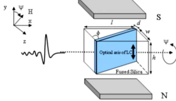
A schematic drawing of the proposed polarizer is shown in Fig. 1. From the top (x – z plane) of a rect-angular parallelepiped made of fused silica (GE124, General Electric), we cut a diagonal groove for filling NLC (E7, Merck). Afterwards, the groove was sealed with a piece of Teflon. Three polarizers with different groove widths, d = 0.75, 1.25, and 1.95 mm, respec-tively, were fabricated to study the thickness depen-dence of the LC layer on polarizing properties of the
device. In the assembled polarizer, there was also a pair of permanent magnets (sintered Nd− Fe− B) that provided a magnetic field 共⬎0.2 Tesla兲 to be suffi-ciently strong to fully align LC molecules along the direction of the field. The rectangular parallelepiped with the NLC layer and magnets can be rotated to-gether about the propagation direction of the THz wave (x axis). The rotation angle,, is defined as the angle between the direction of magnetic field and the y axis.
In the frequency ranging from 0.2 to 1.0 THz, the refractive index of fused silica, ordinary and extraor-dinary refractive indices of E7 are nq= 1.95, no= 1.58, and ne= 1.71, respectively [11]. At the fused-silica–LC interface, the corresponding critical angle for total in-ternal refraction (TIR), co and ce are 54.12° and 61.27°, respectively. Thus we designed the groove angle (incident angle) in the polarizer,= 56± 0.5° (as shown in Fig. 1). At = 90°, the director is perpen-dicular to the polarization direction of the THz wave (o-ray), satisfying the requirement for TIR. At= 0°, the director is parallel to the electric field direction of the THz wave (e-ray), allowing the electromagnetic wave to pass through. The device can thus be oper-ated as a polarizer, as long as ne⬎1.62 and no ⬍1.61. Based on the temperature-dependent indices of refraction of E7 measured in our lab
(unpub-Fig. 1. (Color online) Schematic drawing of the THz
Feussner polarizer with a LC layer. The dimensions of the
device, l⫻w⫻h, are 22.3 mm⫻15 mm⫻15 mm. The
polar-ization direction of the THz wave incident on the polarizer is along the y axis.
1174 OPTICS LETTERS / Vol. 33, No. 11 / June 1, 2008
lished), we conclude that the polarizer will work reli-ably below 57° C, although the nematic range of E7 is from −10° C to 61° C. To guard against temperature fluctuations due to environmental perturbations, one can adopt typical measures for temperature control. The devices were characterized by using a photoconductive-antenna-based THz time-domain spectrometer (THz-TDS) described previously [14]. A pair of parallel wire-grid polarizers (Specac, GS57204) was placed before and after the device to ensure the polarization state of the THz beam trans-mitting through the device. The experiments were conducted at room temperature共23±0.5°C兲.
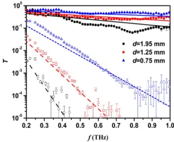
For e-ray, the THz wave incident on the polarizer experienced partial reflection and refraction at the LC–fused-silica interface and attenuation by the LC layer as well as fused-silica prisms. In the experi-ments, we take a rectangular solid fused silica iden-tical to the proposed polarizer, except for the groove as the reference. The transmittance of the polarizer is normalized with respect to that of the reference. The transmitted power spectrum for the e-ray of the THz signal of our polarizer is thus given by [15]
Te共f兲 = Te
⬘
e−4efd⬘/c, 共1兲 whereTe
⬘
=共4nqnecoscosre兲2/共nqcos+ necosre兲4 = 0.801is the power transmittance for the e-ray due to the two fused-silica–LC interfaces, e= 0.007 is the ex-traordinary extinction coefficient of E7 [11], f is the frequency of the THz wave, c is the speed of light in vacuum, d
⬘
= d / cosre is the propagation distance of the refracted THz wave in the LC layer, andreis the refraction angle for the e-ray.For the o-ray, the transmitted intensity of THz sig-nal can be written as [15]
To共f兲 = e−4ofd/ce−2␣d, 共2兲 where o= 0.020 is the ordinary extinction coefficient of E7 [11] and ␣= 2f / c关共nqsin/ no兲2− 1兴1/2 is the decay factor in amplitude of the THz wave in the LC medium.
In this work, the polarizers are characterized by their degree of polarization or polarization factors and extinction ratios. The former, P, is defined by [16]
P =
Te共f兲 − To共f兲
Te共f兲 + To共f兲, 共3兲 where Te共f兲 and To共f兲 are spectral transmittance for e-ray and o-ray, respectively. For an ideal polarizer, P = 1, according to Eq. (3). The extinction ratio is de-fined by
E = To共f兲 Te共f兲
. 共4兲
For an ideal polarizer, E = 0.
The normalized spectral transmittances of e-ray and o-ray for the three polarizers we fabricated are shown in Fig. 2. The theoretical predicted transmit-tance according to Eqs.(1)and(2)are also plotted in Fig. 2. The experimental results are in good agree-ment with theory. The transmittances of the THz wave for o-ray declines significantly with increasing LC layer thickness. This is a manifestation of the higher extinction coefficients of E7 for o-ray.
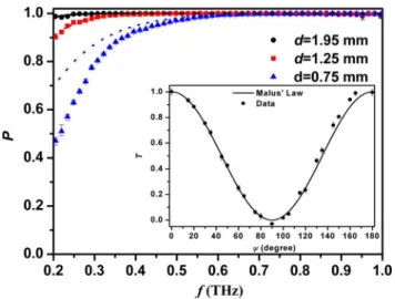
The peak values of the THz field transmitted through the polarizer rotated at different angles with respect to the incident polarization, normalized to the peak value of THz field at= 0°, are plotted in the inset of Fig. 3. The agreement with the theoreti-cal curve according to Malus’ law is excellent.
In Fig.3, we show the experimental data and the-oretical predictions of polarization factors of the three LC THz polarizers. For the polarizer with a 0.75-mm-thick LC layer, P⬎0.95 when f⬎0.44 THz. It is, however, not an effective one in the lower sub-THz frequency ranges, as the LC layer thickness is comparable or shorter than that of the wavelengths. The polarizer with a 1.95-mm-thick LC layer, on the other hand, exhibits the best P value, which is greater than 0.99 for f⬎0.20 THz. For the polarizer with a 1.25-mm-thick LC layer, P⬃0.99 for f ⬎0.32 THz. These results are better than those of the printed wire-grid-type polarizers (0.90 at 0.5 THz) [5] and wire-grid polarizers reported in [17] (0.93 at 2.3 THz). Commercially available far-infrared polar-izers typically are specified with degrees of polariza-tion ranging from 95% to better than 99.99%. The P values of our polarizers rise and approach unity with increasing thickness of the LC layer, because of the higher extinction coefficient of LC for o-rays.
Theoretical and experimental extinction ratios of the three polarizers studied are illustrated in Fig.4. The best E values of the polarizers with 1.95- , 1.25- , and 0.75-mm-thick LC layers are 10−5, 10−5, and 10−3
Fig. 2. (Color online) Normalized transmittance of three polarizers studied. The solid and open marks represent ex-perimental data for e-ray and o-ray, respectively. The black circles, red squares, and blue triangles represent data for polarizers with 1.95-, 1.25-, and 0.75-mm-thick LC layers. The solid and dashed curves are the theoretical curves for e-ray and o-ray, respectively.
at 0.50, 0.70, and 0.75 THz, respectively. Theoreti-cally, the E values of polarizers with 1.95-mm-thick and 1.25-mm-thick LC layers could be as high as 10−11and 10−7, respectively. The discrepancy with the experimental data can be explained as due to the re-duced transmittance of the polarizers at high
fre-quencies and the limit of the signal-to-noise ratio of our THz-TDS 共⬃10−5兲. From Eqs. (3) and (4), we know that the P and E values can be improved by in-creasing the thickness of LC layer, with the penalty of greatly reduced Te values. The three polarizers with 0.75-, 1.25-, and 1.95-mm-thick LC layers are thus suitable for f⬎0.7, 0.7⬎f⬎0.45, and 0.45⬎f ⬎0.3 THz, respectively.
In summary, a Feussner-type THz prism polarizer using a NLC layer is demonstrated. For the polarizer with a 1.95-mm-thick LC layer, the polarization fac-tor is better than 0.99 from 0.20 to 1.00 THz, and the extinction ratio reaches 10−5. This is comparable with that of the common wire-grid polarizers. By choosing different thicknesses of the LC, one can achieve a similar level of performance for THz polarizers in dif-ferent frequency ranges.
This work was supported in part by the Program for Promoting Academic Excellence of Universities Phase II and grant NSC 95-2221-E-009-249 from the National Science Council, as well as the Aiming for the Top University Plan Program of the Ministry of Education of the Republic of China.
References
1. M. Tonouchi, Nat. Photonics 1, 97 (2007) and
references therein.
2. P. F. Goldsmith, Proc. IEEE 80, 1729 (1992).
3. A. E. Costley, K. H. Hursey, G. F. Neill, and J. M. Wald, J. Opt. Soc. Am. 67, 979 (1977).
4. V. B. Yurchenko and E. V. Yurchenko, Millimeter and Submillimeter Waves ’07 Symposium Proceedings (IEEE, 2007).
5. T. Kondo, T. Nagashima, and M. Hangyo, Jpn. J. Appl. Phys., Part 1 42, L373 (2003).
6. K. Feussner, Zeitschr. Instrum. 4, 41 (1884),
summarized by P. R. Sleeman, Nature 29, 514 (1884). 7. T. Yamaguti, J. Phys. Soc. Jpn. 10, 219 (1955).
8. J. C. Martínez-Antón and E. Bernabeuj, Appl. Phys. Lett. 80, 1692 (2002).
9. T.-R. Tsai, C.-Y. Chen, C.-L. Pan, R.-P. Pan, and X.-C. Zhang, Appl. Opt. 42, 2372 (2003).
10. R.-P. Pan, T.-R. Tsai, C.-Y. Chen, C.-H. Wang, and C.-L. Pan, Mol. Cryst. Liq. Cryst. 409, 137 (2004).
11. C.-Y. Chen, C.-F. Hsieh, Y.-F. Lin, R.-P. Pan, and C.-L. Pan, Opt. Express 12, 2625 (2004).
12. F. Rutz, T. Hasek, M. Koch, H. Richter, and U. Ewert, Appl. Phys. Lett. 89, 221911 (2006).
13. M. Oh-e, H. Yokoyama, M. Koeberg, E. Hendry, and M. Bonn, Opt. Express 14, 11433 (2006).
14. C.-L. Pan, C.-F. Hsieh, R.-P. Pan, M. Tanaka, F. Miyamaru, M. Tani, and M. Hangyo, Opt. Express 13, 3921 (2005).
15. E. Hecht, Optics, 3rd ed. (Addison-Wesley Longman, 1998), Chap. 4.
16. J. P. Auton, Appl. Opt. 6, 1023 (1967).
17. V. S. Cherkassky, B. A. Knyazev, G. N. Kulipanov, A. N. Matveenko, P. D. Rudych, and N. A. Vinokurov, Int. J. Infrared Millim. Waves 28, 219 (2007).
Fig. 3. (Color online) Polarization factors of THz LC polar-izers. The black circles, red squares, and blue triangles rep-resent the polarizer with 1.95-, 1.25-, and 0.75-mm-thick LC layers, respectively. The marks and curves are the ex-perimental data and theoretically predicted polarization factors. The inset shows the normalized peak transmission of the THz wave propagated through the THz LC polarizer as a function of the rotation angle,. The solid curve is the theoretical curve according to Malus’ law.
Fig. 4. (Color online) Calculated and measured extinction ratios of three THz LC polarizers. Black (solid), red (dashed), and blue (dotted) lines represent theoretical ex-tinction ratios of the THz polarizer with 1.95-, 1.25-, and 0.75-mm-thick LC layers. Black circles, red squares, and blue triangles represent experimentally determined extinc-tion ratio of THz polarizer with 1.95-, 1.25-, and 0.75-mm-thick LC layers.