Color-saturated and highly efficient top-emitting organic
light-emitting devices
Shih-Feng Hsu
a, Chung-Chun Lee
b, Shiao-Wen Hwang
a, Hsian-Hung Chen
a,
Chin H. Chen
a,*, Andrew T. Hu
baMicroelectronics and Information System Research Center, Department of Applied Chemistry, National Chiao Tung University,
Hsinchu, 30056, Taiwan
b
Department of Chemical Engineering, National Tsing Hua University, Hsinchu, 30055, Taiwan Received 12 February 2004; received in revised form 30 August 2004; accepted 28 October 2004
Available online 28 November 2004
Abstract
Color-saturated and highly efficient top-emitting organic light-emitting devices (OLEDs) were developed. The device structure studied was glass/reflective silver/indium-tin oxide (ITO; 50, 75, 100, 125 and 150 nm, respectively)/organic electroluminescent (EL) stack/calcium (200 2)/ silver (150 2). By changing the thicknesses of ITO from 50–150 nm in the reflective ITO/Ag anode, different emissive colors from bluish green to orange can be obtained from aluminum tris(8-hydroxyquinoline) (Alq3) emitter. By using 2-{2-(t-butyl)-6-[(E)-2-(1,1,7,7-tetramethyl-2,3,6,7-tetrahydro-1H,5H-pyrido[3,2,1-ij]quinoline-9-yl)-1-ethenyl]-4H-4-pyranliden}malonitrile (DCJTB), 10-(1,3-benzothia-zol-2-yl)-1,1,7,7-tetramethyl-2,3,6,7-tetrahydro-1H,5H,11H-pyrano[2,3-f]pyrido[3,2,1-ij]quinoline-11-one (C-545T) and p-bis( p-N,N-di-phenyl-aminostyryl)benzene (DSA-ph) as dopants, highly saturated red, green, and blue (RGB) emissions with Commission Internationale de L’Eclairage chromaticity coordinates of (0.64, 0.36), (0.14, 0.75) and (0.14, 0.08) were obtained, respectively.
D 2004 Elsevier B.V. All rights reserved.
PACS: 85.60.-q; 42.79.-e
Keywords: Luminescence; Optical properties; Optoelectronic devices; Organic semiconductors
1. Introduction
For full color active matrix organic light-emitting devices (OLEDs), a backplane thin film transistors (TFT) design that provides a constant and uniform drive current is very important. The uniformity issue can be resolved by incorporating four or more TFTs in combination with one capacitor in the drive circuit [1,2]. However, the increase in the number of TFTs fabricated on the substrate will invariably reduce the aperture ratio (AR) of each pixel of a bottom-emitting OLED that would in turn require a much higher drive current density to achieve the same level of luminance for display with pixels of larger AR.
Top-emitting organic electroluminescent (EL) devices (TOLEDs), unlike conventional ones, are structurally not affected by the number of TFTs integrated on the substrate as light will emit from the top as all electrical circuits, and TFTs can be hidden below the reflective ITO/Ag anode. As a result, the AR of TOLEDs can be greatly increased, and the operating voltage reduced for a given luminance that could ultimately result in longer operational lifetime of the device. Furthermore, to meet the requirements of a properly balanced white emission of a full color display, the color purity and saturation of each red, green and blue (RGB) subpixels are also critical. In a recent report of projected performance targets for the basic diode needs in high-resolution OLED displays of the future[3], it was suggested that the Commission Internationale de L’Eclairage chroma-ticity coordinates (CIEx,y) of red, green and blue devices are
xN0.7, yN0.75 and (x+y)b0.22, respectively. The reason is that, with increasing saturation of each subpixel of primary
0040-6090/$ - see front matterD 2004 Elsevier B.V. All rights reserved. doi:10.1016/j.tsf.2004.10.038
* Corresponding author. Tel.: +886 3 5712121x59200; fax: +886 5737681.
E-mail address: [email protected] (C.H. Chen).
Thin Solid Films 478 (2005) 271 – 274
RGB emissions, the total power consumption for white light
for a given luminance can be reduced [4]. Unfortunately,
these target goals are not easy to achieve for most known organic luminescent materials because they tend to have broad EL peak with large full width at half maxima (FWHM) about 70–100 nm, which often leads to reduction of color saturation. In the literature, microcavity effect has
been explored to modify the color emissions of OLED[5–
13]. According to the model, Sony has developed a
Top-emission Adaptive Current (TAC) drive scheme, which was reported to improve the color saturation of the red OLED
[14,15]. In this paper, color-saturated and highly efficient TOLEDs were developed with reflective double-layer silver (Ag)/indium-tin oxide (ITO) as anode because of the high reflectance of silver and the desired work function of ITO. Double-layer calcium (Ca)/silver (Ag) were adopted as damage-free cathode which is deposited by thermal evap-oration to eliminate sputtering-induced radiation damages. In addition, optical length of microcavity can be tuned by adjusting the thickness of organic layer and our ITO anode. To the best of our knowledge, no report has been documented on adjusting the emissions of all three primary RGB colors to near National Television Systems Committee (NTSC) saturation by microcavity effect on TOLEDs using simple ITO thickness optimization and the judicious choice of fluorescent dopants.
2. Experimental details
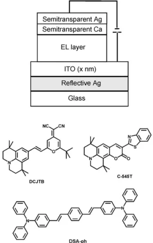
In our experiments, the general structure of our TOLEDs
is shown inFig. 1where ITO thin film is deposited by
low-power radiofrequency magnetron sputtering. In addition, copper phthalocyanine (CuPc) and 4,4V-bis[N-(1-naphthyl)-N-phenyl-amino]biphenyl (NPB) were adopted as the hole injection layer and hole transporter layer, respectively.
Aluminum tris(8-hydroxyquinoline) (Alq3) was adopted
both as the electron transport material and the host emitter for red and green dopants, while 2-(t-butyl)
di-(2-naphthy-l)anthracene (TBADN)[16] was used as the host for blue
dopants. These organic materials were deposited by thermal evaporation in an ULVAC Solciet OLED coater at a base
vacuum of 10 7Torr. Ca and Ag thin films were fabricated
similarly in the separate chamber. The reflectance spectra were recorded on a Steag ETA-Optik spectrometer;
electro-luminescent (EL) spectra, luminance yield and CIEx,y color
coordinates were measured by a Photo Research PR-650 spectrophotometer driven by a programmable DC source.
3. Results and discussions
3.1. Alq3-based devices with various thickness of ITO
In our experiments, different thicknesses of ITO varying from 50, 75, 100, 125 and 150 nm were
sputtered onto Ag (100 nm) to find the optimized reflective anode property, and their reflectance spectra were measured, accordingly. All of the five thin film samples showed similar response throughout the visible range (400–900 nm) with high reflectance (~80%). However, upon fabricating TOLEDs using these anodes
with sequential deposition of CuPc, NPB, Alq3 and
semitransparent cathode layers with fixed thickness, dramatic differences in EL spectra and device
perform-ance were observed as depicted in Fig. 2. When ITO was
50 nm, the EL of Alq3 peaks at 500 nm and its FWHM
was narrowed to only 36 nm. When ITO was increased to 75 nm, the EL peak shifts 516 nm without changing the FWHM. The red shift was continued when ITO increased to 100, 125 and 150 nm with the EL peaks appeared near 572, 608 and 664 nm, respectively. The EL spectra of device with 150 nm of ITO peaks are 664 nm with a very broad shoulder near 570 nm and an additional small peak at 470 nm. These results can be rationalized by the microcavity effect of the ITO layer as, by tuning the thickness of ITO, the EL spectrum is shifted in a wide range (from 500 to 664 nm), and the shape of the EL spectrum is also changed. The
corresponding color change of this Alq3-based TOLED
emitter in term of CIEx,y is shown in the insert of Fig 2.
Fig. 1. The device structure of the TOLED and molecular structures of the three dopants (DCJTB, C-545T and DSA-ph).
S.-F. Hsu et al. / Thin Solid Films 478 (2005) 271–274 272
Using the simple interference law: nintL+Lpenetration=k/2,
we expect that EL spectra of these TOLEDs changes
with: nITODLITO=Dk/2. It matches our experimental
results.
3.2. Optimized TOLEDs with RGB emissive colors
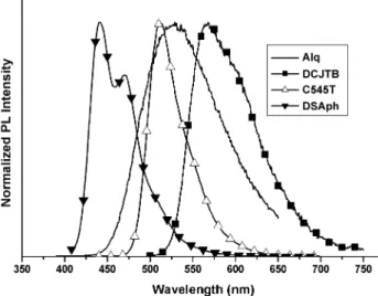
To exploit the microcavity effect of this device, several well-known fluorescent dopants are doped into the TOLEDs. Thus, 2-{2-(t-butyl)-6-[(E)-2-(1,1,7,7-tetra- methyl-2,3,6,7-tetrahydro-1H,5H-pyrido[3,2,1-ij]quinoline-9-yl)-1-ethenyl]-4H-4-pyranliden}malonitrile (DCJTB), 10-(1,3-benzothiazol-2-yl)-1,1,7,7-tetramethyl-2,3,6,7-tetra- hydro-1H,5H,11H-pyrano[2,3-f]pyrido[3,2,1-ij]quinoline-11-one (C-545T) and p-bis( p-N,N-di-phenyl-aminostyryl)-benzene (DSA-ph) are used as red, green and blue dopants, respectively, whose molecular structures and PL
spectra are shown inFigs. 1 and 3, respectively. The RGB
structure of our TOLEDs are Ag(100 nm)/ITO (x nm)/
CFx/NPB (120 nm)/40% Alq3+60% rubrene+2% DCJTB
(30 nm)/Alq3 (50 nm)/Ca (20 nm)/Ag (15 nm) [17], Ag
(100 nm)/ITO(x nm)/ CuPc (15 nm)/NPB (60 nm)/
Alq3+1% C-545T(37.5 nm)/Alq3 (37.5 nm)/Ca (20 nm)/
Ag (15 nm) [18], Ag(100 nm)/ITO (x nm)/CuPc (15 nm)/
NPB (40 nm)/TBADN+5% DSA-ph (20 nm)/Alq3 (20
nm)/Ca(20 nm)/Ag(15 nm) [16], respectively. All of the
organic and cathode layers are constant when ITO thickness varies. By changing the thickness of ITO, the optimized thickness of ITO was chosen to be 75 nm in all of the doped
Fig. 3. PL spectra of Alq3, DCJTB, C545T and DSA-ph.
Table 1
EL performance of DSA-ph, C-545T and DCJTB doped top-emitting OLEDs (the three devices with 75 nm of ITO are measured at 20 mA/cm2, while the other device is measured at 133 mA/cm2; the RGB dopants are DSA-ph, C-545T, and DCJTB for blue, green and red devices, respectively). Thickness of ITO Dopant Voltage (V) Efficiency (cd/A) 1931 CIE FWHM (nm) x y 100 nm Blue 10.0 3.0 0.12 0.37 52 75 nm Blue 7.1 0.9 0.14 0.08 28 75 nm Green 10.0 9.2 0.14 0.75 28 75 nm Red 6.51 7.0 0.64 0.36 32
Fig. 4. (A) Normalized EL spectra of top-emitting (upper) and bottom-emitting (lower) OLEDs doped with DCJTB (E), C-545T (o) and DSA-ph (n). (B)The color gamut achieved by TOLED (E) and bottom-emitting OLED (o) are compared with that of NTSC (n).
Fig. 2. Normalized EL spectra and 1931 CIEx,ycoordinates of TOLEDs
with four different thickness of ITO in the ITO/Ag anode.
devices. The performances of these devices are listed in
Table 1, and their EL spectra are plotted inFig. 4.
Contrary to the bottom-emitting devices, we found the TOLEDs doped with 2% DCJTB, 1% C-545T and 5% DSA-ph show sharper RGB emissions at 608, 514 and 464 nm with FWHM of only 28, 28 and 32 nm, respectively. As can be observed, the emissive colors of all of the doped TOLEDs are purer and more saturated than those of the bottom-emitting ones. The green C-545T doped TOLED shows a luminance efficiency of 9.2 cd/A and saturated
color of CIEx,y (0.14, 0.75). In the blue device, highly
saturated color is also achieved with CIEx,y(0.14, 0.08), but
the efficiency (0.9 cd/A) is not as good as one would like. Although higher efficiency (3.0 cd/A) of blue device can be fabricated with increased thickness of ITO (100 nm), the color is shifted to bluish green with CIEx,y(0.12, 0.37). The
best luminance yield (7 cd/A) and power efficiency (4.8 lm/ w) comes from the red TOLED, which is the most efficient fluorescent dye-doped red OLED ever reported for DCJTB. Comparing at the same doping concentration and color saturation of CIEx,y (0.64, 0.36), the best result from the
bottom-emitting DCJTB doped cohost emitter was 4.5 cd/A
[19].
3.3. Viewing angle of Alq3-based and RGB TOLEDs
consisting of 75 nm of ITO
In this section, viewing angles of Alq3-based and RGB
TOLEDs consisting of 75 nm of ITO are measured.
Luminances vs. viewing angle curves are plotted inFig. 5.
Because of strong microcavity effect, luminance of all TOLEDs reduces to less than half of initial intensity when viewing angle is larger than 458. Therefore, although micro-cavity effect enhances luminance yields and color saturation of these TOLEDs, the effect also limits their viewing angles.
4. Conclusions
In conclusion, we demonstrated color-saturated and highly efficient TOLEDs with different colors from bluish
green to orange in Alq3-based device by changing
thick-nesses of ITO in the ITO/Ag anode. By doping with optimal concentration of DCJTB, C-545T and DSA-ph in the microcavity adjusted structure, brilliant RGB TOLEDs can be obtained with pure and saturated colors that are comparable to NTSC standard.
Acknowledgements
This work was supported by the Ministry of Education of Taiwan, Province of China under the grant of PPUAE (91-E-FA04-2-4-B). The generous supply of OLED materials provided by e-Ray Optoelectronics Technology is gratefully acknowledged.
References
[1] J.H. Lee, W.J. Nam, S.M. Han, M.K. Han, SID Symp. Dig. 34 (2003) 490.
[2] J.C. Goh, C.K. Kim, J. Jang, SID Symp. Dig. 34 (2003) 494. [3] J.N. Bardsley, United States Display Consortium, San Jose, CA
95113, 2002. [http://www.usdc.org/technical/downloads/OLED_ Techroadmap_nbtext.pdf].
[4] H.K. Chung, IDW Symp. Dig. 9 (2002) 12.
[5] A. Dodabalapur, L.J. Rothberg, T.M. Miller, E.W. Kwock, Appl. Phys. Lett. 64 (1994) 2486.
[6] A. Dodabalapur, L.J. Rothberg, T.M. Miller, Electron. Lett. 30 (1994) 1000.
[7] A. Dodabalapur, L.J. Rothberg, T.M. Miller, Appl. Phys. Lett. 65 (1994) 2308.
[8] N. Takada, T. Tsutsui, S. Saito, Appl. Phys. Lett. 63 (1993) 2032.
[9] S. Tokito, K. Noda, Y. Taga, Appl. Phys. Lett. 68 (1996) 2633. [10] P.E. Burrows, V. Khalfin, G. Gu, S.R. Forrest, Appl. Phys. Lett. 73
(1998) 435.
[11] R.B. Fletcher, D.G. Lidzey, D.D.C. Bradley, M. Bernius, S. Walker, Appl. Phys. Lett. 77 (2000) 1262.
[12] F. Jean, J.Y. Mulot, B. Geffroy, C. Denis, P. Cambon, Appl. Phys. Lett. 81 (2002) 1717.
[13] A. Dodabalapur, L.J. Rothberg, R.H. Jordan, T.M. Miller, R.E. Slusher, J.M. Phillips, J. Appl. Phys. 80 (1996) 6954.
[14] T. Sasaoka, M. Sekiya, A. Yamoto, J. Yamada, T. Hirona, Y. Iwase, T. Yamada, T. Ishibashi, T. Mori, M. Asano, S. Tamura, T. Urabe, SID Symp. Dig. 32 (2001) 384.
[15] S. Terada, G. Izumi, Y. Sato, M. Takahashi, M. Teda, K. Kawase, K. Shimotoku, H. Tamashiro, N. Ozawa, T. Shibasaki, C. Sato, T. Nakadaira, Y. Iwase, T. Sasaoka, T. Urabe, SID Symp. Dig. 34 (2003) 1463.
[16] B. Balaganesan, W.J. Shen, C.H. Chen, Tetrahedron Lett. 44 (2003) 5747.
[17] C.Y. Iou, T.H. Liu, H.H. Chen, W.J. Shen, C.H. Chen, SID Symp. Dig. 34 (2003) 971.
[18] C.H. Chen, C.W. Tang, Appl. Phys. Lett. 79 (2001) 3711. [19] T.H. Liu, C.Y. Iou, C.H. Chen, Appl. Phys. Lett. 83 (2003) 5241. Fig. 5. Viewing angle of Alq-based and RGB TOLEDs consisting of 75 nm
of ITO.
S.-F. Hsu et al. / Thin Solid Films 478 (2005) 271–274 274