國
立
交
通
大
學
資訊科學與工程研究所
博
士
論
文
無線網路環境下網際網路電話之效能分析
VoIP Performance Analysis in the Wireless Environment
研 究 生:宋雅琴
指導教授:林一平 教授
無線網路環境下網際網路電話之效能分析
VoIP Performance Analysis in the Wireless Environment
研 究 生:宋雅琴 Student:Ya-Chin Sung
指導教授:林一平 Advisor:Yi-Bing Lin
國 立 交 通 大 學
資 訊 科 學 與 工 程 研 究 所
博 士 論 文
A DissertationSubmitted to Institutes of Computer Science and Engineering Department of Computer Science
College of Computer Science National Chiao Tung University in partial Fulfillment of the Requirements
for the Degree of Ph. D.
in
Computer Science and Engineering June 2010
Hsinchu, Taiwan, Republic of China
中華民國九十九年六月
無線網路環境下網際網路電話之效能分析
學生:宋雅琴
指導教授:林一平 博士
國立交通大學資訊科學與工程研究所博士班
摘要
網際網路電話(VoIP)為目前 IP 網路上最具發展性的通訊方式之一。在無線行動 環境下,頻寬資源有限,並且傳送之可靠性較有線環境為差。為了在無線行動網路中提 供令人滿意的網際網路電話服務,必須保證網路的服務品質(QoS)。 隨著電波射頻技術的演進,頻寬大幅提升,各種無線網路下都可以提供網際網路電 話服務。為達到電信等級的安全度,我們提出整合第三代行動網路與無線網路的認證方 法,在無線網路環境下重複利用全球行動通訊系統(UMTS)的認證金鑰,並且針對 IEEE 802.1X 參數作效能分析以獲得較好的認證延遲效能。 此外,我們研究無線網路下網際網路電話封包的傳送效能。第三代行動合作通訊計 畫(3GPP)標準文件允許被認證的無線網路透過無線接取閘道器/封包資料閘道器 (WAG/PDG)接取第三代行動網路;然而,為確保電信等級的安全度,在行動終端設 備(MS)和無線接取閘道器/封包資料閘道器間的網際網路電話封包必須以網際網路通 訊協定安全性(IPsec)保護。我們分析在無線網路下以網際網路通訊協定安全性加密後 的網際網路電話效能,檢視網際網路通訊協定安全性的額外負擔,包括:封包處理效能, 封包遺失率,封包傳送延遲,以及傳送時間抖動。 最後,我們評估車用環境下網際網路電話的效能。基於 M 台灣計畫,我們在台北 佈建全球互通微波存取(WiMAX)網路以支援高速行動寬頻服務,並在該網路環境中 整合網際網路電話服務。我們研究在上述環境下網際網路電話的效能,其研究成果可作 為未來其他先進的網路環境下分析網際網路效能時的參考。 關鍵字: 網際網路電話,服務品質,效能量測,平均意見分數,基於區域網路的延伸認 證通訊協定,IEEE 802.1X,第三代行動合作通訊計畫,無線接取閘道器/封 包資料閘道器,網際網路通訊協安全性,全球互通微波存取網路,寬頻無線 通訊,電信服務,行動通訊VoIP Performance Analysis in the Wireless Environment
Student:
Ya-Chin
Sung
Advisor:
Dr.
Yi-Bing
Lin
Institute of Computer Science and Engineering
National Chiao Tung University
Abstract
Voice over Internet Protocol (VoIP) is a promising low-cost voice communication over
IP networks. In a mobile/wireless environment, the radio resource is restricted and the reliability of the wireless transmission is much poor than that of the wired environment. To provide satisfactory VoIP services in the mobile/wireless network, the Quality of Service (QoS) of the network should be guaranteed.
Due to the advances of various wireless technologies, the VoIP service is provisioned in different wireless networks. To achieve telecom grade security, we propose a WLAN-3G integrated security approach that reuses the UMTS authentication key in the WLAN environment and conduct a modeling study to tune the IEEE 802.1X parameters to yield better authentication delay performance.
Furthermore, we investigate the VoIP packet delivery efficiency in the wireless environment (i.e., WLAN network). In 3GPP specifications, the authenticated WLAN MS is allowed to access the 3G network through the WAG/PDG. However, to ensure telecom grade security, the VoIP traffic between the MS and the WAG/PDG must be protected with IPsec. We analyze the performance of IPsec-based VoIP service in a IEEE 802.11b WLAN environment. The IPsec overheads in terms of throughput, packet loss rate, latency, and jitter are investigated.
Finally, we present the VoIP performance in the vehicle environment. We conduct trials in the real WiMAX network which supports high-speed mobile broadband services and investigate the WiMAX-based VoIP of a Mobile Taiwan (M-Taiwan) funded program conducted during 2007-08 in the Taipei area. We investigate the VoIP performance in the wireless environment. These research results presented in this dissertation can be viewed as a useful foundation for further VoIP performance study in various advanced wireless environments.
Keywords: Voice over IP, Quality of Service, Performance Measurement, Mean Opinion
Score, EAPOL, IEEE 802.1X, UMTS, WAG/PDG, IPsec, WiMAX, Broadband Wireless Communications, Telecommunication Services, Mobile Communications
Acknowledgement
I would like to express my sincere thanks to my advisor, Prof. Yi-Bing Lin. Without his supervision and perspicacious advice, I can not complete this dissertation. Special thanks are due to my committee members: Dr. Chung-Hwa Rao, Dr. Sheng-Lin Chou, Prof. Han-Chieh Chao, Prof. Chu-Sing Yang, Prof. Ming-Feng Chang, and Prof. His-Lu Chao for their valuable comments and helpful discussions.
I also express my appreciation to all the faculty, staff and colleagues in the Department of Computer Science. In particular, I would like to thank Prof. Shun-Ren Yang, Prof. Pei-Chun Lee, Dr. Lin-Yi Wu, Prof. Sok-Ian Sou, Dr. Shih-Feng Hsu, Dr. Yung-Chun Lin, Prof. Meng-Hsun Tsai, Ms. Hsin-Yi Lee, Mr. Chien-Chun Huang-Fu, Mr. Pin-Jen Lin, Mr. Ren Huang Liou, Mr. Jer-Ming Lin, Mr. Chung-Hsiang Ou, and Mr. Kai-Qun Yang in the Laboratory 117 for their friendship and support in various ways.
Finally, I am grateful to my dear parents, my sisters, my brother, and my boy friend for their unfailing love and firmly support in these years.
Contents
摘要 ... I ABSTRACT ... II ACKNOWLEDGEMENT ... III CONTENTS ... IV LISTS OF TABLES ... VI LIST OF FIGURES ... VII NOTATIONS ... IX CHAPTER 1 INTRODUCTION ... 1
1.1 WIRELESS ACCESS NETWORK ... 4
1.2 CORE NETWORK ... 5
1.3 APPLICATION AND SERVICE NETWORK ... 6
1.4 DISSERTATION ORGANIZATION ... 7
CHAPTER 2 EFFECTS OF THE EAPOL TIMERS IN IEEE 802.1X AUTHENTICATION ... 10
2.1 INTRODUCTION ... 10
2.2 SIM‐BASED IEEE 802.1X AUTHENTICATION ... 13
2.3 EAPOL TIMERS ... 16
2.4 PERFORMANCE MODELING ... 18
2.5 NUMERICAL EXAMPLES ... 23
2.6 SUMMARY ... 28
CHAPTER 3 IPSEC-BASED VOIP PERFORMANCE IN WLAN ENVIRONMENTS ... 29
3.1 INTRODUCTION ... 29
3.2 RELATED WORKS ... 30
3.3 IPSEC‐BASED VOIP EXPERIMENTAL ENVIRONMENT ... 32
3.4 PERFORMANCE MEASUREMENT ... 33
3.4.1 Throughput and Packet Loss Rate ... 33
3.4.2 Latency ... 36
3.4.3 Jitters ... 38
3.5 CONCLUSIONS... 40
CHAPTER 4 M-TAIWAN EXPERIENCE IN VOIP-WIMAX TRIAL ... 42
4.2 VOIP OVERVIEW ... 43 4.2.1 Session Initiation Protocol and Real‐Time Transport Protocol ... 44 4.2.2 E‐Model ... 44 4.3 WIMAX OVERVIEW ... 47 4.3.1 The Media Access Control Layer ... 49 4.3.2 The Physical Layer ... 50 4.4 VOIP EXPERIMENTAL ENVIRONMENT ... 51
4.5 VOIP EXPERIMENTAL SETUP FOR OUTPUT MEASUREMENT ... 56
4.6 WIRELESS‐TO‐WIRELESS VOIP MEASUREMENT RESULTS ... 59
4.6.1 Mean Opinion Score (MOS) ... 60
4.6.2 Packet Loss ... 62
4.6.3 One‐way Packet Delay ... 64
4.6.4 Jitters ... 66
4.7 CONCLUSIONS... 69
CHAPTER 5 CONCLUSIONS AND FUTURE WORK ... 70
5.1 CONCLUDING REMARKS ... 70
5.2 FUTURE WORK ... 71
BIBLIOGRAPHY ... 74
CURRICULUM VITAE ... 78
Lists of Tables
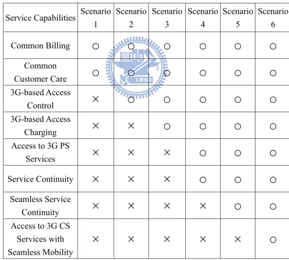
Table 1.1: Interworking Scenarios and Service Capabilities ... 1
Table 2.1: Expected Round-Trip Times for EAP-SIM Authentication Messages (Without Queuing Delays) ... 17
Table 2.2: Input Parameters and Output Measures ... 19
Table 2.3: The pX Values: Analysis Versus Simulation . ... 22
Table 2.4: Effects of TX on pf. ... 23
Table 2.5: Effects of TX and var[tX ] on E[τ]. ... 25
Table 3.1: The Codec Attributes ... 32
List of Figures
Figure 1.1 Mobile/Wireless Network Model ... 4
Figure 1.2: IBM WsT Architecture ... 7
Figure 2.1: A WLAN and Cellular Integration Environment ... 11
Figure 2.2: The Protocol Stack for WLAN and Cellular Integration ... 12
Figure 2.3: SIM-based IEEE 802.1X Authentication Message Flow ... 14
Figure 2.4: The Probability Transition Diagram of the IEEE 802.1X Authentication Message Exchange ... 20
Figure 2.5: Effects of different timeout period settings when var[tX] = 100 × E[tX]2 (X = s, a1, a2, or a3). ... 27
Figure 3.1 The Experimental Environment ... 32
Figure 3.2 Packet Loss and Throughput (N: Number of RTP Streams) ... 34
Figure 3.3 Latency Performance ... 37
Figure 3.4 Jitter Performance (Without Jitter Buffer) ... 39
Figure 4.1 Estimated MOS Value as a Function of Rating Factor R... 46
Figure 4.2 Simplifiied WiMAX Network Architecture ... 48
Figure 4.3 IEEE 802.16 Protocol Stack ... 49
Figure 4.4 M-Taiwan VoIP Experimental Environment ... 52
Figure 4.5 Data Paths in the Experiments ... 53
Figure 4.6 WiMAX CPEs in the Minivan and the WiMAX Antenna ... 53
Figure 4.7 Real-Time Measures of TCP Transmission Rate at Various CPE Speeds ... 54
Figure 4.8 Moving Path for Mobility Tests ... 56
Figure 4.9 MOS Measurements ... 61
Figure 4.11 One-way Packet Delay Measurements ... 66 Figure 4.12 Jitter Measurements ... 68
Notations
The notation used in this dissertation is listed below.
z TX: the associated timeout period of the message exchange X where X = s, a1, a2, or a3
z tX: the RTT of the message exchange X without waiting delay (i.e., the queueing at a
network node) where X = s, a1, a2, or a3
z τX: the response time of the message exchange X (i.e., the RTT of the message exchange
X including the queuing delay) where X = s, a1, a2, or a3
z BX(.): the distribution function of the message exchange service time tX z bX(.): the density function of the message exchange service time tX
z BX*(.): the Laplace Transform of the message exchange service time tX z FX(.): the distribution function of the message exchange response time τX z fX(.): the density function of the message exchange response time τX z FX*(.): the Laplace Transform of the message exchange response time τX z pX: the timeout probability of the message exchange X where X = s, a1, a2, or a3
z λ: the EAPOL message arrival rate to the AP
z pf: the false failure detection probability of the IEEE 802.1X authentication procedure
z E[τ ]: the expected response time of the IEEE 802.1X authentication procedure z N: the number of RTP streams
z Ro: the basic signal-to-noise ratio
z Is: the simultaneous impairment factor
z Id: the delay impairment factor
z Ie-eff: the effective equipment impairment factor
Chapter 1
Introduction
Voice over Internet Protocol (VoIP) is a promising low-cost voice communication over the
wired or wireless Internet network. In the mobile/wireless environment, the radio resource is restricted and the reliability of the wireless transmission is much poor than that of the wired environment. To provide satisfactory VoIP services in the mobile/wireless network, the
Quality of Service (QoS) of the mobile/wireless network should be guaranteed.
Table 1.1: Interworking Scenarios and Service Capabilities Service Capabilities Scenario
1 Scenario 2 Scenario 3 Scenario 4 Scenario 5 Scenario 6 Common Billing
○
○
○
○
○
○
Common Customer Care○
○
○
○
○
○
3G-based Access Control×
○
○
○
○
○
3G-based Access Charging× × ○
○
○
○
Access to 3G PS Services× × × ○
○
○
Service Continuity× × × ○
○
○
Seamless Service Continuity× × × × ○
○
Access to 3G CS Services with Seamless Mobility× × × × × ○
Furthermore, due to the advances of various wireless technologies, the VoIP service is provisioned in different wireless networks. These wireless networks can be integrated with different degrees. Third Generation Partnership Project (3GPP) Technical Report 22.934
conducts a feasibility study on integrating wireless access technologies with cellular (e.g.,
Universal Mobile Telecommunication System; UMTS) mobile system [1]. Six scenarios are
proposed for incremental development of mobile and Wireless Local Area Network (WLAN) interworking. Each scenario enhances interworking functionalities over the previous scenarios as illustrated in Table 1.1. The service and operational capabilities of each scenario are described as follows.
Scenario 1 provides common billing and customer care for both WLAN and mobile operators.
That is, a customer receives a single monthly billing statement combining both mobile and WLAN services. The customer also consults the same customer care center about problems with both services.
Scenario 2 re-uses cellular-access control and charging mechanisms for WLAN services. The
WLAN customers are authenticated by the mobile core network without introducing a separate authentication procedure. In addition, the roaming mechanism between the cellular system and the WLAN is supported. In this scenario, users can access traditional Internet services but cannot access mobile services (such as Circuit Switched (CS) voice and GPRS data services) through the WLAN.
Scenario 3 allows a customer to access mobile Packet Switched (PS) services over the
WLAN. The PS services include Short Message Service (SMS) [2], Multimedia
Messaging Service (MMS) [3], and IP Multimedia Core Network Subsystem (IMS)
Service [4]. Customers equipped with both a WLAN card and a cellular module can simultaneously but independently access WLAN and cellular networks.
Scenario 4 allows a customer to change access between cellular and WLAN networks during
a service session. The system is responsible for reestablishing the session without user involvement. Service interruption during system switching is allowed in this scenario.
QoS is a critical issue for service continuity. Since cellular and WLAN networks have different capabilities and characteristics, the user would gain different QoS grades in different networks. Therefore, QoS adaptation is required during system switching.
Scenario 5 provides seamless service switching (that is, handoff) between the cellular system
and the WLAN. Techniques must be developed to minimize the data lost rate and delay time during switching so that the customer does not experience significant interruption during handoff.
Scenario 6 supports mobile CS services in the WLAN environment. The seamless continuity
feature described in Scenario 5 is also required to support CS services when customers roam between different networks.
Our survey with several mobile service providers indicates that the Scenario 3 features are essential for commercial operation of cellular/WLAN interworking in the first stage deployment. Depending on the business strategies, the Scenario 4 features may or may not be deployed in the long-term commercial operation. Scenarios 5 and 6 are typically ignored because the benefits of the extra features might not justify the deployment costs. This dissertation considers scenario 3 that allows a user to carry out VoIP authentication with 3G mobile core network through WLAN. Then we discuss the VoIP performance in the different wireless networks including the WLAN and the mobile Worldwide Interoperability for Microwave Access (WiMAX) network [5]. Figure 1.1 illustrates a typical mobile/wireless network model studied in this dissertation. According to the network functionalities, the mobile/wireless network model can be partitioned into three categories:
Wireless Access Network (Figure 1.1 (A)) provides wireless connectivity for the Mobile
Station (MS; Figure 1.1 (1)).
Application and Service Network (Figure 1.1 (C)) supports flexible and efficient approaches
for mobile service development and deployment through a service platform.
AAA: Authentication Authorization, and Accounting AP: Access Point
ASN: Access Service Network BS: Base Station
CSCF/MGW: Call Session Control Function/Media Gateway HLR/HSS: Home Location Register/Home Subscriber Server MS: Mobile Station
WAG/PDG: WLAN Access Gateway/Packet Data Gateway WAMAX: Worldwide Interoperability for Microwave Access Wi-Fi: Wireless Fidelity
WLAN: Wireless Local Area Network WsT: WebSphere software for Telecom MS
Wireless Access Network WIMAX Network ASN Gateway Wi-Fi Network Core Network WAG/ PDG CSCF/ MGW HLR/ HSS AAA Server 1 D E 4 B A 2 3 8 7 BS 5 6 AP Application and Service Network C IBM WebSphere Application Server (WsT) 9
Figure 1.1 Mobile/Wireless Network Model
In the remainder of this chapter, we briefly introduce the wireless access network, core network, and application and service network. Then we present the VoIP performance issues concerned in the mobile/wireless network and describe the organization of this dissertation.
1.1
Wireless Access Network
Wireless access network provides wireless connectivity for the MS. In this dissertation, we elaborate on two popular wireless access networks: the WLAN and WiMAX. The WLAN radio network includes 802.11-based Access Points (APs; Figure 1.1 (2)) to provide radio
access for the MSs. In the WiMAX radio network, Base Station (BS; Figure 1.1 (3)) provides radio access for the MSs and connects to Access Service Network Gateway (ASN Gateway; Figure 1.1 (4)), which supports mobility and session management to MS.
To ensure secure communication, both WLAN AP and WiMAX ASN Gateway communicate with the Authentication Authorization, and Accounting Server (AAA Server; Figure 1.1 (5)) in the core network. An MS is required to perform the AAA procedure before associating to the wireless access network. The authentication messages between the MS and the AAA server are forwarded by the WiFi AP (or WiMAX ASN Gateway) when the MS attaches to the WLAN (or WiMAX network). To deliver user data in mobile/wireless network, both AP and ASN Gateway connect to WLAN Access Gateway/Packet Data Gateway (WAG/PDG; Figure 1.1 (6)) to transmit the packets between an MS and the core network. Details of the core network are described in Section 1.2.
1.2
Core Network
The core network provides various mobile services to the MS, such as SMS, MMS, IMS services, etc. In this dissertation, we focus on the IMS services. Specifically, we conduct performance studies on VoIP.
In the core network, AAA server is responsible to mutually authenticate with the MS when the MS associates to the WLAN and the WiMAX networks. WAG/PDG routes the packets received from/sent to the wireless access network. Home Location Register/Home
Subscriber Server (HLR/HSS; Figure 1.1 (7)) is the master database containing all
subscriber-related information. When receiving the authentication request from an MS, the AAA server retrieves the HLR/HSS to obtain the authentication information of the MS. After
the MS is authenticated, the packets between the wireless access network and the core network are routed through WAG/PDG.
The Call Session Control Function (CSCF) and Media Gateway (MGW; Figure 1.1 (8)) are in charge of delivering the call control signaling and the voice data respectively. An example of core network is Chunghwa Telecom (CHT) Next Generation Network (NGN) where IMS plays an important role to offer IP-based multimedia services. In current CHT NGN/IMS deployment, the CSCF is a Nokia Siemens Networks (NSN) CFX-5000, and MGW is an NSN hiG1100.
The core network is integrated with the application and service network by connecting the CSCF with the application server (e.g., IBM WebSphere Application Server; Figure 1.1 (9)) in the application and service network. The CSCF is responsible for processing the requests and responses between the core network and the application and service network. Details of the application and service network are elaborated in Section 1.3.
1.3
Application and Service Network
Application and Service Network supports flexible and efficient approaches for mobile service development and deployment through a service platform. 3GPP defines several alternatives to construct the application and service network platform. In this dissertation, we use the IBM WebSphere application server to illustrate the concept of the application and service network [6]. IBM WebSphere application server is a web application server that offers a platform for creating various web applications. For telecom services, IBM implements
WebSphere software for Telecom (WsT; Figure 1.1 (9)) to provide a platform for efficient
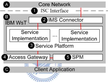
The IBM WsT (Figure 1.2 (B)) interacts with the CSCF in the core network (Figure 1.2 (A)) through the IP Multimedia Subsystem Service Control interface (ISC interface; Figure 1.2 (1)), which is defined in 3GPP TS 23.228 [4]. The ISC interface supports Session
Initiation Protocol (SIP), which is a signaling protocol widely used for controlling multimedia
communication sessions. In IBM WsT, ISC interface is supported in IMS Connector (Figure 1.2 (2)), which is in charge of processing the SIP request and responses between the IBM application server and the CSCF in the core network.
Figure 1.2: IBM WsT Architecture
IBM WsT provides a service platform (Figure 1.2 (3)) that allows third parties to implement their applications using Parlay X Application Programming Interfaces (APIs), which are web service APIs for developing telecommunication services. The service platform interacts with the client application (Figure 1.2 (C)) through the access gateway (Figure 1.2 (4)), which is in charge of service access control and user authorization based on the policies defined in the Service Policy Manager (SPM; Figure 1.2 (5)).
1.4
Dissertation Organization
the VoIP performance in the mobile/wireless network environment. In Chapter 2, we study the authentication delay for real-time applications such as VoIP. Before VoIP call setup, the MS (i.e., a call party) is required to attach to the mobile network and be authenticated. In our study, the authentication key in UMTS can be reused in the IEEE 802.1X authentication mechanism in WLAN environment to achieve telecom grade security. In this WLAN-3G integrated security approach, we conduct a modeling study to tune the IEEE 802.1X parameters to yield better authentication delay performance.
In Chapter 3, we investigate the VoIP packet delivery efficiency in the wireless environment (i.e., WLAN network). In 3GPP specifications, the authenticated WLAN MS is allowed to access the 3G network through the WAG/PDG. However, to ensure telecom grade security, the VoIP traffic between the MS and the WAG/PDG must be protected with IPsec. We analyze the performance of IPsec-based VoIP service in a IEEE 802.11b WLAN environment. The IPsec overheads in terms of throughput, packet loss rate, latency, and jitter are investigated.
In Chapter 4, we present the VoIP performance in the vehicle environment. We conduct trials in the real WiMAX network which supports high-speed mobile broadband services and investigate the WiMAX-based VoIP of a Mobile Taiwan (M-Taiwan) funded program conducted during 2007-08 in the Taipei area. For the worst-case-scenario, the tests were conducted under a stringent condition of both communicating devices, wirelessly connected to the same WiMAX base station under a heavy background traffic and interference, were experiencing simultaneous handovers during the communication. The results show excellent performance for the VoIP applications when both Customer Premise Equipments (CPEs) are stationary. An acceptable VoIP performance is observed when the CPEs move at the speeds up to 50 Km/h.
Finally, we conclude this dissertation in Chapter 5 by discussing our contributions and future work.
Chapter 2
Effects of the EAPOL Timers in IEEE
802.1X Authentication
This chapter studies IEEE 802.1X authentication for WLAN and cellular integration. In the IEEE 802.1X standard, several timeout timers are defined for message exchanges in the EAPOL protocol, where the same fixed value is suggested for these timeout timers. We observe that the delays for the EAPOL message exchanges may significantly vary. A modeling study is performed to tune the values of individual timers to yield better performance than that for the identical timeout period setting. Our study provides guidelines to select appropriate timeout values for IEEE 802.1X operation.
2.1
Introduction
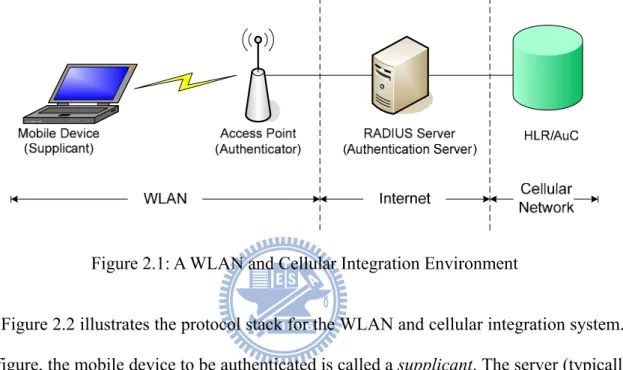
The IEEE 802.1X standard specifies authentication and authorization for IEEE 802 LAN [7], which has also been widely adopted for mobile devices to access WLAN. Furthermore, if WLAN is integrated with cellular network (such as GSM or UMTS [8]), the SIM module (in the mobile device) and the Authentication Center (AuC) are utilized together with IEEE 802.1X for authentication. An example of WLAN and cellular integration (in terms of authentication) is illustrated in Figure 2.1.
In this figure, the HLR is a mobility database that stores and manages all mobile subscriptions of a specific operator. The AuC provides security data management for mobile subscribers. The AuC is typically collocated with the HLR. The AP provides radio access to a mobile device. Before a mobile device is authenticated, the AP only allows this mobile device to send
the IEEE 802.1X authentication messages. When the Remote Authentication Dial In User
Service (RADIUS) server receives an authentication request from the mobile device, it
retrieves the authentication information of the mobile device from the HLR/AuC. After the HLR/AuC returns the authentication information, the RADIUS server authenticates the mobile device following the standard GSM/UMTS authentication procedure [9].
Figure 2.1: A WLAN and Cellular Integration Environment
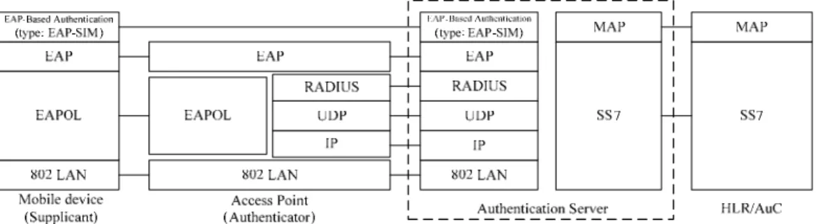
Figure 2.2 illustrates the protocol stack for the WLAN and cellular integration system. In this figure, the mobile device to be authenticated is called a supplicant. The server (typically a RADIUS server) performing authentication is called the authentication server. The
authenticator (e.g., a wireless access point) facilitates authentication between the IEEE
802.1X supplicant and the authentication server.
The integrated system utilizes the Extensible Authentication Protocol (EAP) to support multiple authentication mechanisms based on the challenge-response paradigm [10]. The IEEE 802.1X supplicant encapsulates the EAP packets in EAP over LAN (EAPOL) frames before they are transmitted to the authenticator. Upon receipt of an EAPOL frame, the authenticator decapsulates the EAP packet from the EAPOL frame. Then the EAP packet is sent to the authentication server using the RADIUS protocol [11]. Implemented on top of UDP, RADIUS provides mechanisms for per-packet authenticity and integrity verification
between the authenticator and the authentication server.
Figure 2.2: The Protocol Stack for WLAN and Cellular Integration
IEEE 802.1X authentication for the WLAN and cellular integration network has been investigated in [12], [13] and [14]. These studies focused on the design of the network integration architectures, and proposed IEEE 802.1X authentication procedures for the integration network. In [15], we proposed an integration solution for Third Generation (3G) and WALN services, called the WLAN-based GPRS Support Node (WGSN). WGSN re-uses 3G mechanisms for WLAN user authentication and network access without introducing new procedure and without modifying the existing 3G network components. In WGSN, the mobile device must obtain an IP address before it is authenticated by the HLR/AuC. This chapter describes IEEE 802.1X authentication that enhances the WGSN security by allowing a mobile device to be authenticated before it is assigned an IP address.
In our solution, the WLAN and cellular integration network in Figure 2.1 employs EAP-SIM authentication, which is an EAP-based authentication protocol utilizing the GSM Subscriber
Identity Module (SIM) [16]. In GSM, a secret key Ki is stored in the HLR/AuC as well as in
the SIM. The authentication server communicates with the HLR/AuC to obtain the GSM authentication information through the Mobile Application Part (MAP) implemented on top of the Signaling System Number 7 (SS7) protocol [8]. In the EAP-SIM authentication, the MAP is responsible for retrieving the GSM authentication information in the HLR/AuC.
In the implementation of IEEE 802.1X authentication for WGSN, we observe that the elapsed times for authentication message pairs exchanged between the mobile device and the network are different. In IEEE 802.1X specification, the message pairs are associated with fixed timeout timers. We analyze the timeout timers used in IEEE 802.1X authentication and improve the performance of IEEE 802.1X authentication by selecting appropriate timer values.
2.2
SIMbased IEEE 802.1X Authentication
This section describes the SIM-based IEEE 802.1X authentication procedure. The authentication message flow is illustrated in Figure 2.3, which consists of the following steps:
Stap 1. The mobile device (the supplicant) sends the EAPOL‐Start packet to the AP to initiate
the IEEE 802.1X authentication.
Stap 2. The AP requests the identity of the mobile device through the EAP‐Request message
with type Identity. When the AP receives the EAP‐Response/Identity message from the mobile device, it encapsulates this message in the Access‐Request packet. Then the packet is sent to the RADIUS server.
Stap 3. Upon receipt of the Access‐Request packet, the RADIUS server conducts the
EAP-SIM authentication with the mobile device (the supplicant). Specifically, the RADIUS server generates an Access‐Challenge packet that encapsulates the EAP‐Request/SIM/Start in the EAP-Message attribute and sends it to the AP. This message requests the mobile device to initiate the EAP-SIM authentication. The AP decapsulates the EAP‐Request from the Access‐Challenge packet, and delivers it to the mobile device by an EAPOL packet.
Figure 2.3: SIM-based IEEE 802.1X Authentication Message Flow
Stap 4. The mobile device responds the RADIUS server with the EAP‐Response/SIM/Start
message containing a random nonce AT_NONCE_MT. The random nonce will be used to generate the encryption key for data transmission between the mobile device and
the RADIUS server after the IEEE 802.1X authentication.
Stap 5. To obtain the authentication information of the mobile device, the RADIUS server
sends the SS7 MAP_Send_Authentication_Info_Request message (with the argument IMSI) to the HLR/AuC.
The HLR returns the authentication vector (RAND, SRES, Kc) through the SS7 MAP_Send_Authentication_Info_Response message, where RAND is a random number generated by the HLR/AuC. By exercising the GSM authentication algorithm
A3, both the SIM module and the HLR/AuC use the RAND and the secret key Ki to
produce a signed result SRES (see Step 7). The RADIUS server will authenticate the mobile device by comparing the signed result SRES* generated by the SIM module with the SRES generated by the HLR/AuC (see Step 8). If they are equal, the mobile device is successfully authenticated and an encryption key Kc* is produced by the GSM encryption/decryption key generation algorithm A8 (using Ki and RAND as inputs)[8].
Stap 6. The RADIUS server sends the EAP‐Request/SIM/Challenge (with the parameter RAND,
which is encapsulated as AT_RAND) to the mobile device. To ensure the integrity of the challenge message, the message contains a Message Authentication Code (MAC) AT_MAC. Detailed usage of MAC can be found in [16], and will not be elaborated here.
Stap 7. After verifying AT_MAC received from the RADIUS server, the mobile device passes
the random number RAND to the SIM module to perform GSM authentication. The SIM module computes its signed result SRES* and the encryption key Kc* based on the received RAND and the authentication key Ki stored in the SIM card. Then the mobile device sends SRES* (encapsulated in AT_MAC) to the RADIUS server through
the EAP‐Response/SIM/Challenge message.
Stap 8. The RADIUS server verifies AT_MAC and compares SRES* calculated by the mobile
device with the SRES received from the HLR/AuC. If the values are identical, the RADIUS server notifies the AP that authentication is successful through the EAP‐Success message (encapsulated in the RADIUS Access‐Accept packet). The AP passes the EAP‐Success message to the mobile device. At this point, the mobile device is allowed to access the network through the AP. If the signed results are not the same, the RADIUS server notifies the AP that the authentication fails through the EAP‐Failure message (encapsulated in the RADIUS Access‐Reject packet).
2.3
EAPOL Timers
In the IEEE 802.1X supplicant (mobile device), three EAPOL timers are defined:
1. startWhen (associated with message pair ●a in Figure 2.3): When the IEEE 802.1X supplicant initiates the authentication, it sends EAPOL-Start to the authenticator and starts the startWhen timer. If the supplicant has not received any response from the authenticator after this timer expires, it resends EAPOL-Start. The supplicant gives up when it sends EAPOL-Start for n1 times. In the IEEE 802.1X specification [7], the default n1 value is 3.
The default value of the startWhen timer is 30 seconds.
2. authWhile (associated with message pairs ●b, ●c, and ●d in Figure 2.3): Every time the supplicant sends an authentication message (Steps 2.2, 4.1, and 7.1 in Figure 2.3), it starts the authWhile timer. If the supplicant does not receive any response from the authenticator after this timer has expired, the supplicant sends an EAPOL‐Start message to re-start the authentication procedure. The supplicant gives up after it has consecutively sent
EAPOL‐Start for n2 times. The default n2 value is 3. The default value of the authWhile
timer is 30 seconds.
3. heldWhile (associated with Step 8.2 message in Figure 2.3 if the client fails the authentication): If the IEEE 802.1X authentication fails, the supplicant has to wait for a period heldWhile before it re-starts the authentication procedure. The default value of the
heldWhile timer is 60 seconds.
Selection of the EAPOL timer values is not trivial. If the timer value is too large, it will take long time before the mobile device detects the failure of the network (e.g., RADIUS server failure). If the timer value is too small, the timer may expire before the mobile device receives the response message. In this case, the mobile device needs to re-start the authentication process due to false failure detection.
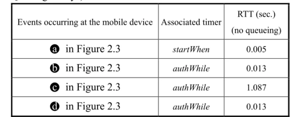
Table 2.1 shows the expected Round-Trip Times (RTTs) of message exchanges that measured from the WGSN implemented in National Chiao Tung University. These measurements do not experience waiting delays due to queuing at the network nodes (i.e., AP, RADIUS server and HLR/AuC).
Table 2.1: Expected Round-Trip Times for EAP-SIM Authentication Messages (Without Queuing Delays)
Events occurring at the mobile device Associated timer RTT (sec.) (no queueing) ●a in Figure 2.3 startWhen 0.005 ●b in Figure 2.3 authWhile 0.013
●c in Figure 2.3 authWhile 1.087 ●d in Figure 2.3 authWhile 0.013
In our measurement, the mobile device and the AP are located in one subnet. The RADIUS server and the HLR are located in another subnet. The data rate of the fixed network is
100Mbps. It is observed that the RTT of a message exchange between the mobile device and the RADIUS server are much shorter than that of a message exchange between the mobile device and the HLR/AuC. This significant RTT discrepancy is due to the fact that accessing the HLR/AuC is much more time-consuming than accessing the RADIUS server. This phenomenon is especially true when the HLR/AuC is fully loaded by cellular user accesses and when the RADIUS server and the HLR/AuC are located at different cities or different countries. To reduce the false failure detection probability without non-necessary timer timeout delay, the values of the startWhen timer and authWhile timers should not be identical for all message exchanges in the IEEE 802.1X authentication. For example, the authWhile timer for ●c in Table 2.1 should be different from that for ●b and ●d.
2.4
Performance Modeling
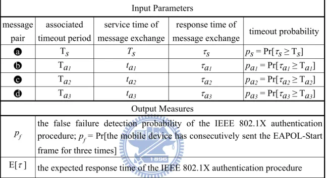
We propose an analytic model to investigate the false failure detection probability pf of the
IEEE 802.1X authentication procedure and the expected elapsed (response) time E[τ] for executing the IEEE 802.1X authentication procedure. Input parameters and output measures used in the model are listed in Table 2.2.
In Table 2.2, tX is the RTT of the message exchange without waiting delay (i.e., the queueing
at a network node) where X = s, a1, a2, or a3. This RTT is called “service time” in the
queueing model. For our measurement in Table 2.1, E[ts] =0.005 seconds, E[ta1] = 0.013
seconds, E[ta2] = 1.087 seconds, and E[ta3] = 0.013 seconds. The response time τX of the
message exchange is the RTT of the message exchange including the queuing delay. Since we cannot conduct large-scale service trial in our IEEE 802.1X prototype, τX are derived from the service times using the M/G/1 queuing model. Let EAPOL message arrivals to the AP be a Poisson stream with rate λ. The service time tX of the message exchange has an arbitrary
distribution with the distribution function BX(.), the density function bX(.), and the Laplace
Transform BX*(.). The response time of the message exchange is represented by the random
variable τX, which has the distribution function FX(.), the density function fX(.) and the Laplace Transform FX*(.).
Table 2.2: Input Parameters and Output Measures Input Parameters message pair associated timeout period service time of message exchange response time of
message exchange timeout probability ●a Ts Ts τs ps = Pr[τs ≥ Ts]
●b Ta1 ta1 τa1 pa1 = Pr[τa1 ≥ Ta1]
●c Ta2 ta2 τa2 pa2 = Pr[τa2 ≥ Ta2]
●d Ta3 ta3 τa3 pa3 = Pr[τa3 ≥ Ta3]
Output Measures
pf the false failure detection probability of the IEEE 802.1X authentication procedure; p
f = Pr[the mobile device has consecutively sent the EAPOL-Start
frame for three times]
E[τ ] the expected response time of the IEEE 802.1X authentication procedure
By applying the Pollaczek-Khintchine transform equation for the sojourn time, we can express FX*(.) as [18]: FX*(s) = BX*(s)
∑
k = 0 ∞ (1– l E[tX]) (l E[tX] )k ⎝ ⎜ ⎛ ⎠ ⎟ ⎞ 1 – BX*(s) s E[tX] k , (2.1)where X = s, a1, a2, or a3. The density function fX(.) can be obtained by inverting the Laplace
Transform FX*(.) in (1). Therefore, we have
fX ( tX ) = bX ( tX ) +
∑
k = 0 ∞
(1– l E[tX]) (l E[tX] )k ^b(k)( tX ), (2.2)
where ^b(k)( tX ) is the k-fold convolution of the function
1 – BX (tX) E[t ]
Let TX be the timeout period associated with the timer for the message pair X and pX be the
timeout probability of the message exchange.
pX = Pr[ τX ≥ TX ] = ⌠∞
⌡TX fX ( t ) d t (2.3)
The expected response time E[τX] of the message exchange can be obtained by differentiating
the Laplace Transform FX*(.).
E[τX] = pX TX + (1 – pX ) ⌠TX
⌡0 t fX ( t ) d t (2.4)
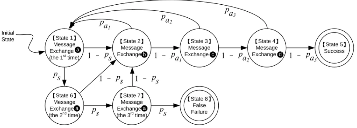
The probability transition diagram of the mobile device is illustrated in Figure 2.4. In IEEE 802.1X, the AP can also control the number of retransmissions for EAPOL‐Start (○1 in
Figure 2.3) sent from the mobile device to the AP. To simplify our discussion, we assume that the number of retransmissions is sufficiently large, so that the state diagram in Figure 2.4 is not affected. Initial State 【State 8】 False Failure 【State 5】 Success ps ps ps 1 – ps 1 – ps 1 – ps 1 – pa1 1 – pa2 1 – pa3 pa1 pa2 pa3 【State 1】 Message Exchange (the 1st time) a 【State 6】 Message Exchange (the 2nd time) a 【State 2】 Message Exchangeb 【State 7】 Message Exchange (the 3rd time) a 【State 4】 Message Exchanged 【State 3】 Message Exchangec
Figure 2.4: The Probability Transition Diagram of the IEEE 802.1X Authentication Message Exchange
to state ○1 again) whenever the authWhile timer (associated with message exchanges ●b, ●c,
and ●d) expires. The authentication exits and is considered failed if the startWhen timer (associated with message exchange ●a) has consecutively expired for three times (i.e., the
finite state machine (FSM) moves from state ○1 , ○6 , ○7 , to state ○8 ).
Let x be the probability that the FSM starts from state ○1 and eventually comes back to state
○1 (i.e., state ○1 may be revisited zero or more times). All possible scenarios for the
probability transitions in Figure 2.4 are described as follows:
Scenario I: From state ○1 (i.e., state ○1 may have been visited zero or more times), the
startWhen timer consecutively expires for three times (i.e., the last transitions are
○1 Æ○6 Æ○7 Æ○8 ). The probability for Scenario I is xps3.
Scenario II: From state ○1 , the startWhen timer consecutively expires for two times, and the
procedure successes at the third try (i.e., the last transitions are ○1 Æ○6 Æ○7 Æ○2
Æ○3 Æ○4 Æ○5 ). The probability for Scenario II is x ps2 ( 1 – ps )( 1 – pa
1 )( 1 –
pa2 )( 1 – pa3 ).
Scenario III: From state ○1 , the startWhen timer expires once, and the procedure successes at
the second try (i.e., the last transitions are ○1 Æ○6 Æ○2 Æ○3 Æ○4 Æ○5 ). The
probability for Scenario III is xps( 1– ps )( 1 – pa1 )( 1 – pa2 )( 1 – pa3 ).
Scenario IV: From state ○1, the procedure successes without incurring any timer expiration
(i.e., the last transitions are ○1 Æ○2 Æ○3 Æ○4 Æ○5 ). The probability for Scenario
IV is x ( 1 – ps )( 1 – pa1 )( 1 – pa2 )( 1 – pa3 ).
It is apparent that the false failure probability pf is the probability that Scenario I occurs. The
pf = Pr[Scenario I occurs] = xps3 (2.5)
and
1 – pf = Pr[Scenarios II, III, or IV occur]
= x( ps2 + ps1 + 1)( 1 – ps )( 1 – pa1 )( 1 – pa2 )( 1 – pa3 )
= x( 1 – ps3)( 1 – pa1 )( 1 – pa2 )( 1 – pa3) (2.6)
From (2.5) and (2.6), we have
pf + (1 – pf ) = x [ps3 + ( 1 – ps3)( 1 – pa1 )( 1 – pa2 )( 1 – pa3)] (2.7) By rearranging (2.7), we have x = 1 ps3 + ( 1 – ps3 ) ( 1 – pa1 ) ( 1 – pa2 ) ( 1 – pa3 ) (2.8) From (2.8) and (2.5), pf = ps 3 ps3 + ( 1 – ps3 ) ( 1 – pa1 ) ( 1 – pa2 ) ( 1 – pa3 ) (2.9)
By using (2.3) and (2.9), the value of pf can be computed from λ, fs, fa1, fa2, and fa3. Table 2.3: The pX Values: Analysis Versus Simulation
(TX = 10 × E[tX], var[tX ] = E[tX]2,and X = s, a1, a2, or a3).
(UNIT: E[T1 X]) 0.2 0.4 0.6 0.8 SIMULATION 0.0003 0.0025 0.0183 0.1353 ANALYTIC 0.0004 0.0027 0.0196 0.1271 ERROR 0.0001 0.0002 0.0013 0.0082
The above analytic model is validated against simulation experiments. The simulation model follows the discrete event approach [19], and the details are omitted. Table 2.3 indicates that the analytic and the simulation results are consistent (the errors are within 1%). Therefore, both the analytic model and the simulation implementation are validated.
2.5
Numerical Examples
This section uses numerical examples to investigate the impact of timers on the performance of IEEE 802.1X authentication. The input parameters and the output measures are listed in Table 2.2. The expected service times of the EAPOL message exchanges E[ts], E[ta1], E[ta2],
and E[ta3] are obtained from the measurements as listed in Table 2.1. Other parameters
include the EAPOL message arrival rate λ, and the variances of the EAPOL service times (i.e.,
var[tX], where X = s, a1, a2, or a3). We have the following observations.
Table 2.4: Effects of TX on pf (var[tX] = 100 × E[tX]2; X = s, a1, a2, or a3).
Timeout Timers
(Unit: second) Arrival Rate ⎝⎜ ⎛ ⎠ ⎟ ⎞ Unit: 1 E[ta2] Ts Ta1 Ta2 Ta3 0.900 0.950 0.975 5 10 10 10 0.0199 0.3473 0.9569 15 10 10 10 0.0000 0.0023 0.5000 10 5 10 10 0.0000 0.0574 0.8676 10 15 10 10 0.0000 0.0314 0.7510 10 10 5 10 0.0000 0.0416 0.8140 10 10 15 10 0.0000 0.0344 0.7801 10 10 10 5 0.0000 0.0582 0.8679 10 10 10 15 0.0000 0.0317 0.7527
Observation 1. The probability pf is mainly affected by pS .
lim
ps→1 pf = 1 and limps→0 pf = 0.
Observation 2. The probabilities pa1, pa2, and pa3 have indirect impact on pf .
Increasing pa1, pa2, and pa3 will increase the probability that the FSM moves toward state ○1
(i.e., loops among states ○1 , ○2 , ○3 , and ○4) and thus decrease the probability that the FSM
enters state ○5 . However, the effect in Observation 2 is not as significant as that in
Observation 1.
Based on simulation experiments, Table 2.4 shows how timeout period TX (X = s, a1, a2, or a3)
affects pf when the variance of tX is large (i.e., var[tX] = 100 × E[tX]2). These results in Table 2.4 are consistent with Observations 1 and 2. That is, TS has more significant effect on pf than
Ta1, Ta2, and Ta3 do, especially when the EAPOL message arrival rate λ is high. Specifically,
when λ = 0.975 × E[ta2]–1 and if Ta1, Ta2, and Ta3 are fixed to 10 seconds, changing the value of TS from 5 seconds to 15 seconds will reduce pf from 95.69% to 50.00% (about 50%
improvement). Conversely, changing any of the values for Ta1, Ta2, and Ta3 from 5 to 15
seconds only insignificantly affects pf (less than 13% improvement).
When var[tX] is small (e.g., var[tX] is less than E[tX]2), the service time tX does not significantly vary, and the IEEE 802.1X authentication message exchange is more likely to complete if the value for TX is set larger than the expected service time E[tX] of the
corresponding EAPOL message pair exchange. Therefore, we have the following observation.
Observation 3. When var[tX] is small and TX is sufficiently large, changing TX only
insignificantly affects pf .
to 0.5 × E[ta2]–1. From this table, we have the following observations.
Observation 4. When var[tX] is small (i.e., var[tX] = E[tX]2), E[τ] is insignificantly affected by the change of TX if TX is larger than the expected response time of the EAPOL message
exchanges. This result is similar to that in Observation 3.
Table 2.5: Effects of TX and var[tX ] on E[τ] (X = s, a1, a2, or a3; λ = 0.5 × E[ta2]–1).
Timeout Timers
(Unit: second) var[tX] = E[tX]
2 var[t
X] = 100 × E[tX] 2
Ts Ta1 Ta2 Ta3 E[τ] effects E[τ] effects
5 10 10 10 2.24 decreasing 0.45% 11.00 decreasing 0.09% 15 10 10 10 2.23 10.99 10 5 10 10 2.24 decreasing 0.45% 10.96 decreasing 0.36% 10 15 10 10 2.23 11.00 10 10 5 10 2.25 decreasing 0.89% 7.26 increasing 96.01% 10 10 15 10 2.23 14.23 10 10 10 5 2.24 decreasing 0.45% 11.17 decreasing 1.70% 10 10 10 15 2.23 10.98
We also observe two effects on TX .
Effect 1. When TX is increased, the probability pX is decreased, and the number of looping
among states ○1 , ○2 , ○3 , and ○4 is reduced.
When the variance of service time var[tX] is increased, more large tX periods are expected.
Therefore, even if TX is increased, these long EAPOL message delays still result in timeouts,
and pf cannot be significantly reduced. Therefore, we have
Effect 2. When TX is increased, if timeout does occur, the non-necessarily waiting for timeout
is increased and E[τ] is increased.
Based on the above discussion, we examine the results in Table 2.5 as follows.
Observation 6. If var[tX] is large and TX is not much larger than E[tX] (e.g., 5 seconds < TX <
10 seconds), then increases TX only insignificantly decreases pf (indicated in Observation 5),
but significantly increases extra waiting period for timeout described in Effect 2. Therefore E[τ] is significantly increased. This phenomenon occurs for changing Ta2 in Table 2.5, where E[Ta2] = 1.087 seconds.
When E[tX] << TX , then even if var[tX] is large, it is still likely that tX < TX , and both Effects 1
and 2 are not significant. Instead, the situation is similar to that in Observation 4. That is, E[τ] is insignificantly affected by var[tX] and TX when E[tX] << TX . The phenomena occur for
changing Ts, Ta1, and Ta2 in Table 2.5, where these timeout periods TX are larger than 500 ×
E[tX].
A comparison of different timers settings is shown in Figure 2.5. In Cases 1, 2, and 3, the timers in different message pairs are set to identical values, which means that a fixed authWile timer is used in message pairs ●b, ●c, and ●d (as suggested in IEEE 802.1X standard). In Case 4, we adjust the values of the timers according to the previous discussions to obtain better performance. For the illustration purpose, It is assumed that the variance of service time
var[tX] is 100 × E[tX]2. Similar results are observed for different variances and are not presented in this study. Figure 2.5 indicates that the false failure detection probability pf is
zero if the timeout period Ts is larger than 10 seconds and the EAPOL message arrival rate λ is below 0.925 × E[ta2]
–1. Theses figure indicate that when
λ < 0.925 × E[ta2]
–1, Case 4 has
three Cases. When λ > 0.925 × E[ta2]–1, Case 4 improves E[τ] at the cost of degrading p f as
compared with Cases 1 and 2. For all λ values, Case 1 outperforms Case 2, and Case 2 outperforms Case 3 in terms of the pf measure. For the E[τ] performance, the result reverses. In Case 3, the total timeout value Ts + Ta1 + Ta2 + Ta3 = 40 seconds. For Case 4, the total
timeout value is 55 seconds. It is interesting to note that for all values, Case 4 outperforms Case 3 for both pf and E[τ] performances. Also note that when λ > 0.925 × E[ta2]–1, the system is saturated, and will not occur in most commercial operations.
Figure 2.5: Effects of different timeout period settings when var[tX] = 100 × E[tX]2 (X = s, a1, a2, or a3).
In these numerical examples, we demonstrate that appropriate TX values can be selected
through our modeling study to yield better performance than the fixed TX value setting.
2.6
Summary
This chapter described IEEE 802.1X authentication for WLAN and Cellular integration. We presented the protocol stack and the authentication message flow, and measured the response times of all EAPOL message exchanges in the IEEE 802.1X authentication for the integrated system implemented in NCTU.
In the IEEE 802.1X standard, a fixed-value timer is used in all authentication message exchanges, which does not reflect the real network operation. A modeling study was presented in this chapter to tune the values of individual timers, which yields better performance than the fixed timeout period setting.
Our study provides guidelines to select appropriate timeout periods for corresponding authentication message exchanges. For example, comparing with the fixed timeout periods setting where TX are set to 10 seconds, the suggested setting for the timeout periods (i.e., Ts = 10 seconds, Ta1 = 10 seconds, Ta2 = 5 seconds, and Ta3 = 30 seconds) decreases the false
failure detection probability pf and significantly improves the expected response time E[τ] of the IEEE 802.1X authentication procedure.
Chapter 3
IPsec-Based VoIP Performance in
WLAN Environments
3GPP specifies 3G-WLAN interworking that allows a Mobile Station (MS) to access the 3G network through a WLAN Access Gateway/Packet Data Gateway (WAG/PDG), and specifies that the packets delivered between the MS and the WAG/PDG should be protected with IPsec. This chapter studies the performance of IPsec-based VoIP service in a WLAN environment. The IPsec overheads in terms of throughput, packet loss rate, latency, and jitter are investigated. Our study provides guidelines to select appropriate system parameter values for VoIP over WLAN.
3.1
Introduction
The 3GPP Technical Specification 23.234 [20] specifies 3G-WLAN interworking that extends 3G services to the WLAN environment. In 3G-WLAN interworking, a Mobile Station (MS) in the WLAN accesses the 3G core network through a WLAN Access Gateway/Packet Data
Gateway (WAG/PDG). The security requirements are enforced such that between an MS and
the WAG/PDG, IPsec security association is established and the transmitted packets are protected by IPsec with Encapsulating Security Payload (ESP) in the tunnel mode [21]. In an IPsec tunnel, an original IP packet, including the header and the payload, is encrypted and authenticated, and a new IP header is added to route the packet between the MS and the WAG/PDG. Before sending an IP packet, the MS checks the security policies applied to the
packet and performs IPsec encapsulation according to the methods defined by the security association. When receiving an IPsec packet, the WAG/PDG validates and decapsulates the packet according to the security information of the corresponding security association. By exercising IPsec encapsulation, the sizes of the packets transmitted between the MS and the WAG/PDG increase and the performance degrades.
Voice over Internet Protocol (VoIP) provides voice communications over Internet [15], where Session Initiation Protocol (SIP) [22] is often used to control the call and Real-time Transport Protocol (RTP) [23] is used to deliver the voice data. Several codecs can be used in the RTP
calls to meet the bandwidth restrictions. In a 3G-WLAN interowking environment, the VoIP performance may be degraded due to IPsec encapsulation. This chapter investigates the performance of IPsec-based VoIP in the WLAN environment, and is organized as follows. The related works are elaborated in Section 3.2. Our experimental environment is described in Section 3.3, and the performance measures (throughput, packet loss rate, latency, and jitter) are reported in Section 3.4. Based on the performance measurements, Section 3.5 suggests proper system parameter setups for IPsec-based VoIP in the WLAN environment.
3.2
Related Works
The IPsec performance for VoIP in the wireless environments has been investigated in [24, 25, 26, 27]. The latency performance for IPsec security association was investigated in [25]. The study in [24] presented the IPsec performance for VoIP by evaluating speech quality with G.711 codec. The speech quality was evaluated by a subjective method called Mean Opinion
Score (MOS). The study in [25] measured IPsec-based VoIP over 3G-WLAN interworking
system with different types of codecs. The studies in [26, 27] investigated the VoIP performance with mathematical analysis and simulation experimentsof network capacity (in
terms of the number of supported RTP streams).
In the previous experimental studies, the performance measurement tools were run on the MS, which may affect the accuracy of the reported results. In [24], the QoS measurement tool developed by the authors was executed on the MS. In [25], four tools were executed on the MS, including RTP Tools to send and receive the RTP packets, network monitor tools pktstat and Netperf to measure the network traffic and collect the performance data, and Ethereal to record network packet events on the MS. In our experiments, all performance data are collected and measured by Smartbit. The MS only processes the VoIP packets as in the normal operation mode, and its computing power is not consumed for measurement.
The performance results presented in the previous studies are quite different due to different experimental setups and the output measures defined. The MOS measure considered in [24] provides useful insight for voice quality. However, it does not reflect the effect of delays. Also the IPsec performance in terms of packet loss, latency, and jitter were not presented. The analytical studies in [26, 27] showed the IEEE 802.11b AP capacity for plain VoIP without packet loss. They did not consider the relationships between the throughput and the VoIP traffic load. The performance results in [25] are not consistent with that in [26, 27]. On the other hand, we conduct our measurements by setting the same experimental parameters to those in [26, 27], and obtain the consistent results
All these previous studies did not consider heavy VoIP traffic issues that are further elaborated in this chapter. Heavy traffic analysis provides useful insight to a VoIP operator to determine what kinds of codec and packet loss concealment techniques should be employed. We also elaborate on the IPsec overhead in terms of latency, and compare the jitter performance for VoIP with and without IPsec. These aspects were not investigated in the previous studies.
3.3
IPsecbased VoIP Experimental Environment
Figure 3.1 illustrates a simplified 3G-WLAN integration system, where the MS (Figure 3.1 (1)) is a laptop equipped with Pentium M 1.3GHz CPU and 256MB memory. The WAG/PDG (Figure 3.1 (2)) is a laboratory prototype implemented in a PC equipped with Pentium IV 3.0 GHz CPU and 1GB memory. The MS communicates with the WAG/PDG via a D-Link DL-524 IEEE 802.11b access point (AP; Figure 3.1 (3)). The AP connects to the WAG/PDG through the Ethernet where the peak rate is 10Mbps. The Smartbit (Figure 3.1 (4)) is utilized for performance measurement [28], and is connected to the MS and the WAG/PDG using CAT 5 cables with the RJ-45 interface.
Figure 3.1 The Experimental Environment Table 3.1: The Codec Attributes
Codec G.711 G.729
Bit Rate
64 Kbps, sampling at an 8 KHz rate with 8 bits per sample
8 Kbps, sampling at a 1 KHz rate with 8 bits per sample
Sample Period 20 ms 10 ms
RTP Payload Length (Sample Rate x Sample Period)
160 Bytes, one frame per RTP packet
10*2 Bytes, two frames are combined into one RTP packet
RTP Packet Rate 50 packets/sec 50 packets/sec MS Smartbit (2) WAG/PDG (4) (3) AP (1)
In the experiments, the Smartbit generates multiple RTP streams identified with different source/destination IP address pairs, and injects them to the MS. The RTP packets are transmitted over UDP. Two kinds of voice codecs, G.711 [29] and G.729 [30], are used in generating the RTP streams. G.711 is a high bit-rate codec with a sample period of 20 ms. G.729 is a low bit-rate codec with a sample period of 10 ms. The codec attributes are summarized in Table 3.1.
When the MS receives the RTP packets from the Smartbit, it encapsulates these packets with IPsec ESP in the tunnel mode. The RTP packets are encrypted by the 3DES algorithm [31], and are authenticated by the HMAC-SHA-1-96 algorithm [32]. Then the encapsulated packets are sent to the WAG/PDG via the IPsec tunnel. Upon receipt of the IPsec packets, the WAG/PDG executes the IPsec decryption procedure. The decrypted RTP packets are then collected by the Smartbit. From the measured packets, the Smartbit produces the output statistics.
3.4
Performance Measurement
Based on the experimental environment described in Section 3.3, we measure the IPsec overhead in terms of throughput, packet loss rate, latency, and jitter.
3.4.1 Throughput and Packet Loss Rate
Figure 3.2 (a) illustrates the packet loss rate measured by the Smartbit. The study in [26, 27] derived an upper bound for the VoIP capacity (in terms of the number of the supported RTP streams) over IEEE 802.11b without packet loss. By using the equation derived in [26, 27], we compute the upper bound of network capacity for IPsec-based VoIP. Table 3.2 compares
the VoIP capacity without packet loss between the measured values in our experiments (Figure 3.2) with the upper bounds derived in [26, 27]. This table shows that the measured capacity without packet loss achieves about 85% of the calculated upper bound capacity. Table 3.2 also indicates that after IPsec encryption, the capacities without packet loss degrade by 4% (in terms of the number of RTP streams supported) for G.729 and 5% for G.711, respectively.
(a) Packet Loss Rate (b) Throughput Figure 3.2 Packet Loss and Throughput (N: Number of RTP Streams) Table 3.2 Measured Capacities without Packet Loss and Their Upper Bounds Codec IPsec Encrypted Upper Bound Capacity Measured Capacity
G.729 no 24.1 RTP Streams 20 RTP Streams
yes 23.2 RTP Streams 19 RTP Streams
G.711 no 21.5 RTP Streams 18 RTP Streams
yes 20.7 RTP Streams 17 RTP Streams
for G.711 with packet loss rate less than 1%. This result is probably misleading because the reported number of VoIP connections (i.e., 28) exceeds the capacity upper bound derived in [26, 27]. Our experiments and the studies in [26, 27] show that when the packet loss rate is less than 1%, the IEEE 802.11b AP can only support 20 and 17 IPsec VoIP connections for G.711, respectively.
Figure 3.2 (a) indicates that to maintain the same packet loss rate, the system can support one less IPsec RTP streams than original RTP streams. For examples, when the packet loss rate is 10%, the system can support 21.86 original RTP streams or 21.13 IPsec RTP streams for G.729 (i.e., the IPsec overhead is 3.34%), and can support 20.02 original RTP streams or 19.15 IPsec RTP streams for G.711 (i.e., the IPsec overhead is 4.35%).
Figure 3.2 (a) also shows that as the system attempts to support more RTP streams (and therefore the packet loss rate increases), the IPsec overhead becomes less significant. For example, when the packet loss rate increases from 5% to 20%, the IPsec overhead decreases from 3.80% to 3.29% for G.729, and from 5.12% to 3.55% for G.711.
Based on the mathematical analysis in [26, 27], we further derive the capacity of an IEEE 802.11b AP for IPsec VoIP. Figure 3.2 (a) indicates that the packet loss rate increases to 5% – 6.3% when the VoIP traffic is one RTP stream larger than the network capacity without packet loss. This result is consistent with the simulation results in [26, 27].
Figure 3.2 (b) illustrates the throughput performance. We note that the following relationship holds:
Packet Loss Rate = Arrival Rate × Packet Size – Throughput Arrival Rate × Packet Size


![Table 2.4: Effects of T X on p f (var[t X ] = 100 × E[t X ] 2 ; X = s, a 1 , a 2 , or a 3 )](https://thumb-ap.123doks.com/thumbv2/9libinfo/8597360.189980/35.892.265.671.706.1018/table-effects-t-x-var-x-e-x.webp)
