行政院國家科學委員會專題研究計畫 成果報告
寬頻合作式無線多輸出入通訊系統--子計畫二:合作式多
輸出入下行考慮同步不確定之傳收器設計(2/2)
研究成果報告(完整版)
計 畫 類 別 : 整合型 計 畫 編 號 : NSC 99-2219-E-009-009- 執 行 期 間 : 99 年 08 月 01 日至 100 年 07 月 31 日 執 行 單 位 : 國立交通大學電子工程學系及電子研究所 計 畫 主 持 人 : 桑梓賢 計畫參與人員: 碩士班研究生-兼任助理人員:呂宗達 碩士班研究生-兼任助理人員:連哲聖 碩士班研究生-兼任助理人員:李俊育 碩士班研究生-兼任助理人員:蔡耀賢 碩士班研究生-兼任助理人員:林建志 博士班研究生-兼任助理人員:林欣德 報 告 附 件 : 出席國際會議研究心得報告及發表論文 處 理 方 式 : 本計畫涉及專利或其他智慧財產權,2 年後可公開查詢中 華 民 國 100 年 08 月 31 日
行政院國家科學委員會補助專題研究計畫
■成果報告
□期中進度報告
寬頻合作式無線多輸出入通訊系統-子計畫二:合作式多輸出入下
行考慮同步不確定之傳收器設計(2/2)
計畫類別:
□
個別型計畫
■
整合型計畫
計畫編號:NSC 99 - 2219 - E - 009 - 009
執行期間:99 年 8 月 1 日至 100 年 7 月 31 日
執行機構及系所:
國立交通大學電子工程學系(所)
計畫主持人:桑梓賢
共同主持人:
計畫參與人員:林欣德、呂宗達、林哲聖、李俊育、蔡耀賢
成果報告類型(依經費核定清單規定繳交):
□
精簡報告
■
完整報告
本計畫除繳交成果報告外,另須繳交以下出國心得報告:
□赴國外出差或研習心得報告
□赴大陸地區出差或研習心得報告
■出席國際學術會議心得報告
□國際合作研究計畫國外研究報告
處理方式:
除列管計畫及下列情形者外,得立即公開查詢
■涉及專利或其他智慧財產權,□一年■二年後可公開查詢
中 華 民 國 100 年 8 月 30 日
摘要
本計畫所設定的研究目標為:解決寬頻合作式無線多輸出入通訊系統在用戶端高速移 動下,因通道衰落及同步誤差所造成的系統效能損失。高速移動環境所造成的通道衰落及 載波間干擾問題,一直是無線通訊的核心問題,我們從實用角度出發,重新檢視現有方法 的侷限,並提出新的解決方案。合作式系統因 4G 標準開始討論協作式多點傳輸( CoMP ) 而有了新的意義,但如何解決多點同步問題也浮上檯面。互相合作形成陣列的天線分散在 極為不同的傳輸環境中,因而無法像傳統處於同一地點的傳送天線陣列達成載波頻率及符 元時間的完全同步。我們經由兩個面向提出同步問題的解決方案。首先我們從設計接收機 著手,我們考慮廣泛使用的阿拉木提多輸出入系統,為其設計一套對同步誤差具有超強容 忍力的接收機,數值模擬結果表明它運用於單載波系統可抵抗極大的載波頻率誤差,運用 於多載波系統則可抵抗極大的符元時間誤差。另外、我們也從編碼設計的角度解決同步問 題。在這裡,我們不將同步誤差視做必須避免的問題,反而視為多集性增益的可能來源。 經由為合作式多輸出入通訊設計一種位元交錯編碼調變方式,我們發現、當同步誤差存在 時、多集性增益也大幅增加。 關鍵詞:合作式通訊、協作式多點傳輸、正交分頻多工、載波間干擾、同步、阿拉木提、 位元交錯編碼調變 AbstractThe goal set in this project is to solve issues caused by fading channels and synchronization errors arise from deploying broadband cooperative Multiple-Input Multiple-Output (MIMO) systems with highly mobile users. Performance degradation caused by fading channels and inter-carrier interference has always been a core issue for mobile communications. We consider these problems from the angle of practical deployment and point out limitations of various existing advanced methods. We also provide a good and practical solution. Cooperative MIMO obtains new meanings since the 4G standard meetings began discussing Coordinated Multi-Point (CoMP) transmission. This also leads to the urgent needs to solve unique challenges of synchronization. The synchronization issues have unique characteristics due to the fact that cooperating transmitters may be distributed physically and thus may be situated in widely different transmission environments, contrasting to co-located transmitters with which the carrier frequencies and symbol clocks can be synchronized perfectly. In this project we aim to addressing synchronization errors in cooperative MIMO systems from two perspectives. The first is to design a receiver which is extremely tolerant with synchronization errors when used in combination with common Alamouti schemes. Simulation results show that the receiver can retain the diversity order even when large carrier frequency offsets exit in single-carrier systems and large symbol timing errors in multi-carrier systems. The second perspective is to solve the problem via code design. Instead of viewing synchronization errors as impairments, we treat them as potential sources of diversity gain. A Bit-Interleaved Coded Modulation (BICM) scheme is eventually developed for cooperative scenarios in which the diversity order can be dramatically increased when synchronization errors exist.
Key words: cooperative communications 、 CoMP 、 OFDM 、 inter-carrier interference 、
目錄
1.
前言 ... 4
2.
ICI Cancellation in OFDM Systems over Time Varying Channels ... 6
2.1 ICI Models ... 7
2.2 ICI Indicator ... 8
2.3 Per-subcarrier Adaptive ICI Cancellation Framework... 10
2.4 Computational Complexity ... 13
3.
Multiple Carrier Frequency Offsets in Cooperative Communications ... 14
3.1 System Model ... 15
3.2 Multiple CFOs Mitigation... 17
3.3 Time-Frequency Duality and Single-Carrier Systems ... 19
3.4 Simulation Results ... 20
3.
BICM-OFDM to Combat Multiple Synchronous Errors ... 22
3.1 System Model ... 22
3.2 The Receiver Algorithm ... 24
3.3 Simulation Results and Discussion ... 26
4.
結果與討論 ... 28
5.
計劃成果自評 ... 28
1. 前言
在第四代無線通訊系統中, 3GPP LTE (3rd
Generation Partnership Project Long Term Evolution,第三代合作夥伴計劃長期演進技術) 以傳輸距離長、傳輸速率高、佈建快、成 本低等特性,已和 WiMAX 成為最被看好的無線寬頻技術。 LTE 的標準主要部分 Release 8 已 於 2009 年 完 成 [1] 。 參 考 各 國 際 大 廠 日 前 介 紹 參 與 制 定 行 動 LTE-advanced 和 WiMAX[2]規格的近況,往後發展計畫要能在時速 350 Km/hr 的如此快速移動狀態下的傳 輸速率可達 100 Mb/s,在固定使用無線數據傳輸速率時可達 1Gb/s。 為了達到如此高的傳輸速率以及保持在高速移動狀態時訊號的可靠度,必須採用 MIMO (多根傳輸天線-多根接收天線) 技術。而合作式(cooperative)或分散式(distributed)的 MIMO 技術更開始廣受標準組織的青睞。例如, LTE-advanced 開始討論協作式多點傳輸 Coordinated Multi-Point (CoMP) transmission 用以改善細胞邊緣的訊號條件及胞內傳輸速 率的提升,其工作原理示意圖如下所示。而 IEEE 802.16e 中規範了一個稱為「協力空間多 工(collaborative spatial multiplexing)」的選項(optional)技術,可以讓兩個用戶台協力進行上 行傳輸,但兩個用戶台需要知道彼此的上傳資料。IEEE 802.16j[3]所規範的是中繼站(relay station, RS)技術,規範了中繼站群組(RS grouping)及合作中繼(cooperative relaying),可以透 過兩個或更多個中繼站來共同向同一用戶台傳送同樣的訊號。IMT-Advanced 可能也都會將 協作式多點傳輸及中繼站視為整個系統的重要組件,自始就納入標準規範。這些標準制定 活動表明廣義上的合作式(cooperative) MIMO 會是熱門的無線通訊技術之一。
本子計畫基於總計畫提出的之合作式無線多輸出入通訊系統(請見下圖),結合 4G 標準 中實體層的下行部分(downlink)所採用的 OFDMA (Orthogonal Frequency Division Multiple Access,正交分頻多工進接),研究高速移動環境所造成的通道衰落及載波間干擾問題,以 及有多重同步誤差的情況下,通道估測、接收機設計等下行相關議題,以下就此一新技術 趨勢之可能優點及待解決的下行訊號處理挑戰做一綜述。
圖二、參考系統架構示意圖,其中 BS = base station, RS = relay station, MS = mobile station。
正交分頻多工(OFDM)系統以其高度頻譜效能著稱,且是 4G 標準的傳輸技術不二人 選,在標準要求的高速移動狀況下,通道將會受到強烈的多普勒效應(Doppler spreading), 同時也會有嚴重的衰落(fading),正交分頻多工訊號會面臨一個很嚴重的問題,即載波間干 擾(inter-carrier interference, ICI ),文獻中已有許多減輕 ICI 的技術[5]-[16],某些甚至有 一流效能表現,然而各種實際問題限制了它們的應用,具成本效益與良好表現的方法仍為 業界急需,我們從實用角度出發,重新檢視現有方法的侷限,並提出新的解決方案。
合作式 MIMO 由於各基地台/中繼站參數以及與行動台間的通道狀況並不相同且時常 改變,因而帶來幾點可能的優勢[18]-[22]:第一、更大的範圍延伸(range extension)。第二、 解決因通道的鴿洞效應(pigeon hole effect)而導致的多集增益(diversity gain)的損失。第三、 更彈性地使用頻帶達成吞吐量強化(throughput enhancement)。我們認為若更有效的利用不 同使用者間的共同資訊(User Diversity)可進一步增進系統效能。
由於下行合作式多輸出入系統的特性,有三項獨特的訊號處理議題亟需解決:1.因高 速移動及多個基地台/中繼站各不相同的傳輸參數和都卜勒狀況而產生嚴重的訊號品質下 降。2.各基地台/中繼站對同一移動台而言有不同的最佳符元時間(symbol timing)以及載波頻 率偏移(multiple carrier frequency offsets),因而有同步的不確定性。3. 合作式 MIMO 系統 的通道狀態資訊(CSI, Channel State Information)估測通常較點對點 MIMO 系統更為複雜, 因而簡單且有效的通道估測,也是研究熱點。
本計畫針對同步誤差以及高速移動下的傳輸參數不確定性,經由兩個面向提出解決方 案。首先我們從設計接收機著手,我們考慮廣泛使用的 Alamouti 多輸出入系統[23],為其 設計一套對同步誤差具有超強容忍力的接收機,數值模擬結果表明它運用於單載波系統可
抵抗極大的載波頻率誤差,運用於多載波系統則可抵抗極大的符元時間誤差。另外、我們 也從編碼設計的角度解決同步問題。在這裡,我們不將同步誤差視做必須避免的問題,反 而視為多集性增益的可能來源。經由為合作式多輸出入通訊設計一種位元交錯編碼調變 (BICM)方式[24],我們發現、當同步誤差存在時、多集性增益竟大幅增加,我們也對此結 果做了一些理論分析。至此、在 Alamouti 編碼以及 BICM 的情況下之同步問題,已獲得初 步解決,唯目前開發的接收機演算法仍具高複雜度,降低複雜度也是我們努力的方向。 以下關於技術部分的章節,由於行文方便性的考量,將以英文撰寫,對讀者造成的任 何不便,作者深表歉意。
2. ICI Cancellation in OFDM Systems over Time Varying
Channels
First, we address the most common anomaly that faces typical mobile devices, especially those devices that employ the current modulation technique of choice – OFDM. In time-varying (TV) channels, the channel frequency response (CFR) matrix of OFDM systems is no longer diagonal and the off-diagonal terms contribute to ICI. ICI can cause serious performance degradation in OFDM systems and many ICI cancellation techniques have been proposed over the years to deal with the imperfect CFR matrix; see [5]-[16] and references therein. In [5], [7], [8], [12], [15], frequency-domain zero-forcing (ZF) or minimum mean square error (MMSE) ICI equalizers are proposed, while time-domain equalizers are investigated in [6]. For these methods, the major computational cost comes from matrix inversion. So far the means to reduce the cost is imposing the ICI matrix to a banded structure in which all but few elements on selected diagonals are set to zero [5]. With the banded structure, matrix inversions of smaller sizes are used to calculate coefficients of MMSE or ZF ICI equalizers. A rule of thumbs in [9][12] is to choose the bandwidth parameter Q is Q ≥ fD/f + 1, where fD is the maximum Doppler
frequency and f denotes the subcarrier spacing. However, the BER performance can degrade
severely when Q is not large enough.
Other advanced techniques such as nonlinear ICI equalizers offer superb performance, but they may have limited implementation readiness due to either higher computational cost or limitations specified by standards. Popular wireless broadband access technologies such as WiMAX (IEEE 802.16e) and LTE both choose orthogonal frequency division multiple access (OFDMA) as the downlink transmission scheme. This will cause problems for decision feedback or iterative equalizers, such as those in [7] and [9]; they may not be suitable for OFDMA due to the need to know CFR information or data on other users’ or un-occupied subcarriers. Another
technique, the turbo ICI equalizer [13][14], requires CFR information, the feedback from the channel decoder, and has longer processing latency due to its iterative nature. Some techniques that utilize time-domain windowing [9][10] can greatly extend the supported Doppler spread range but the white noise will be colored and the receiver has to handle it to avoid performance degradation [17]. The MAP and MLSE equalizers [16] offer the best performance yet the cost is still too high. Methods based on basis expansion model [10][16] also need to consider issues of channel estimation and model fitting.
In short, to develop a simple ICI equalizer with adequate performance still means much practical significance to the communication industry. In this paper, we focus on improving the inner receiver and developing low-complexity methods that can provide decent performance for standards such as WiMAX or LTE. We start with a popular model of linearly time-varying channel is reviewed and some observations are noticed as the inspiration of our per-subcarrier approach. We propose a simple ICI indicator is proposed to show the relative severity of ICI on each individual subcarrier. Its statistical properties, in particular the probability density function (PDF), are investigated to lay a theoretical foundation for adapting the ICI equalizer according to the ICI indicator and estimating the possible saving in computational complexity. Based on the ICI indicator, a per-subcarrier adaptive framework which can work with most existing ICI cancellation methods, especially linear ICI equalizers, is proposed to further reduce computational complexity while maintaining performance. Several examples demonstrate how the framework operates. Especially, a novel low-complexity perturbation-based ICI equalizer is developed with the emphasis on implementation readiness and adequate performance. Simulations are provided and savings in computational cost are calculated to show the effectiveness of our approach.
2.1 ICI Models
Consider the baseband equivalent OFDM system model with N subcarriers, the length of one transmitted OFDM symbol is NS = N + NCP in which NCP is the length of the cyclic prefix.
The received signal on the i-th subcarrier is:
where Sm is the data symbol on the m-th subcarrier, Hi,m represents the Channel Frequency
Response (CFR), and Zi is white Gaussian noise. ICI on the i-th subcarrier caused by the signal
on the m-th transmit subcarrier comes through the ICI channel Hi,m. We organize Hi,m into a
matrix and that is the ICI channel matrix H. Thus we can compactly represent the ICI signal model in the matrix form:
where Havg is the diagonal averaged channel matrix part which is not affected by the Doppler
spread and is a diagonal channel matrix variation part and G is a fixed ICI channel gain matrix which together with reflect the effect of Doppler spread.
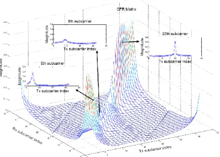
The ICI model in provides more insights when it is examined at the subcarrier-level granularity. For example, the magnitude of a 32 32 CFR matrix and cross-sections at three different subcarriers are shown in Fig. 3. The first thing to notice is that there is no uniform band structure in the CFR matrix, since each subcarrier faces very different ICI situations. This observation gives us an idea of adapting the ICI-cancellation method according to the ICI situation on each sub-carrier. Once this is done, we expect that the computational cost of ICI cancellation can be dramatically decreased since most of the sub-carrier, even at very high speed, do not really need extensive ICI treatment. As can be seen from the next sub-section, this observation is verified by studying the statistical properties of a certain “ICI indicator”.
Fig. 3. The magnitude of a typical ICI channel matrix for a highly mobile user terminal
2.2 ICI Indicator
From Fig. 3, we see that the ICI situations at each sub-carrier are quite different. Therefore, we would like to devise a measurement which can reflect the different ICI situation at each sub-carrier. It is found that the ratio k/Hk (k is the sub-carrier index) can do the job. Given a
value of |k/Hk|, the corresponding signal-to-interference ratio (SIR) can be easily calculated. In
22 dB), is affected by insiginificant amount of ICI and requires no ICI cancellation. When the signal experiences moderate fading, like on the 5-th subcarrier, |k/Hk | becomes higher (between
−5 and 0 dB, corresponding to SIR from 22 to 12 dB), and a small truncated CFR matrix, say a 3×3 matrix, might be needed for adequate ICI cancellation. If deep fading occurs, as on the 9-th subcarrier, |k/Hk | becomes significant (|k/Hk | > 0 dB corresponds to SIR < 12 dB), and a larger
CFR sub-matrix will be needed for ICI cancellation. The term |k/Hk | seems able to reflect the
ICI situation on each subcarrier.
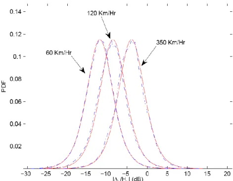
Fig. 4. Probability density functions (solid) and histograms (dash-dotted) of the ICI indicator for vehicle speed at 60, 120, and 350 km/h.
To better utilize |k/Hk | as the ICI indicator, its statistical properties need to be investigated.
Assume Rayleigh fading channels, k and Hk can be approximated by two independent complex
Gaussian random variables (RVs), and their absolute values follow the Rayleigh distribution. We found that the PDF of |k/Hk| can be found by calculating the convolution of two log-Rayleigh
PDFs. Simulation is conducted to verify the derived PDF, using WiMAX standard with 10 MHz bandwidth, 2.5 GHz central carrier frequency, 1024 subcarriers, and the ITU Vehicular-A channel model. Fig. 4 shows the theoretical PDF and the histogram 10log10(|k/Hk|) for various
vehicle speeds, and they coincide closely. Recall that larger |k/Hk| means higher ICI level, it can
be seen that as vehicle speed gets higher, more subcarriers experience severe ICI; yet even at 350 km/h, there are still 85% of subcarriers on which |k/Hk| < 0 dB and simple ICI equalizers may
be good enough. It is worth noting that the distribution of 10log10(|k/Hk|) does not depend on the
channel’s power delay profile (PDP) since no assumption about the PDP needs to be made in the derivation. This is also confirmed through simulations with other channel models. Table I lists
the percentages of the ICI indicator in four ranges (<= −5 dB, −5 ~ −3 dB, −3 ~ 0 dB, and => 0 dB) against various vehicle speeds. The table can also be used in evaluating the benefit of reducing complexity by adapting ICI cancellers according to the ICI indicator.
TABLE I
ICI indicator, distribution under different vehicle speed
2.3 Per-subcarrier Adaptive ICI Cancellation Framework
We have learned that the ICI situation is quite different for each sub-carrier. So an intuitive way to treat ICI is to adaptively adjust your method from sub-carrier to sub-carrier.
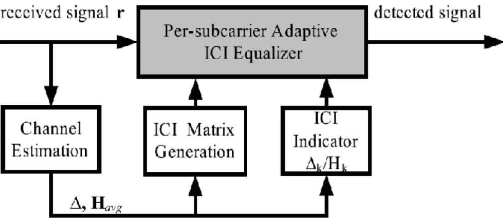
Fig. 5. Per-subcarrier adaptive ICI cancellation framework
Fig. 5 shows our proposed receiver architecture utilizing the ICI indicator. The per-subcarrier adaptive ICI equalizer adjusts its setting according to |k/Hk|. The overall
computational complexity can be greatly reduced with little performance degradation. The concept is simple and intuitive, yet has not been seen in the existing literature. In addition, it works well with popular wireless access technologies such as WiMAX and LTE based on OFDMA. Not only can it be exploited in signal detection but also used for channel estimation, in
which only the averaged CFR (Hk) needs to be estimated and (k) is simply the difference
between Hk of adjacent OFDM symbols. Next, two examples are shown on how the framework
incorporates conventional ICI equalizers.
First, consider linear equalizers. In a linear “block” ICI equalizer, usually a bandwidth parameter Q is chosen and only the lower and upper Q diagonal in the ICI channel matrix are considered and the whole banded ICI channel matrix is inverted to generate equalized signals. The parameter Q is selected according to the channel condition, but the value, once chosen, is fixed for all sub-carriers.
In a linear “serial” ICI equalizer, a smaller (2Q+1) (2Q+1) matrix is inverted for each sub-carrier, since the whole ICI channel matrix is not inverted, the computational cost is dramatically reduced. But, again, the value of Q, once chosen, remains the same for all sub-carriers.
In our approach, however, instead of a fixed Q for every subcarrier, it is chosen according to |k/Hk|. In this way, much computation cost is saved without hurting performance. Note that
block and serial ZF equalizers can be easily obtained.
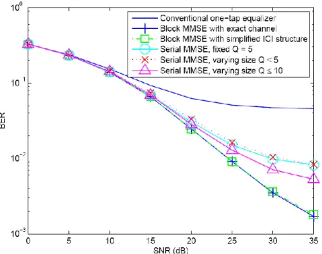
Fig. 6. BER performance comparisons for linear ICI equalizers under 1024-point FFT, 64-QAM, and ITU Vehicular-A channel model at 350 km/h.
Fig. 6 shows results with un-coded systems. So, what happens when channel coding is added? It is worth noting that our proposed methods far exceed the performance requirements of say, the WiMAX standard when mandatory channel coding is used. For example, our per-subcarrier adaptive ZF perturbation method achieves 10% packet error rate at 16 dB SNR at
350 km/h, while the standard requires only 60 km/h. Follow the same simulation set-up in Section III with NA = 864 active subcarriers in the 1024- point FFT mode, BER comparisons of different ICI equalizers are shown in Fig. 6. The block MMSE ICI equalizer needs to invert a 864 × 864 matrix, either with the exact CFR matrix or a simplified approximation. The serial MMSE ICI equalizer inverts a local small CFR sub-matrix for each subcarrier to achieve lower complexity. The matrix size is set by Q which conventionally is fixed for all subcarriers. Our per-subcarrier adaptive ICI equalizer adjusts Q according to the ICI indicator. In our simulation,
Q is chosen from the four settings (Q = 0, 1, 3, and 5) corresponding to the four ranges (≤ −5 dB,
−5 ~ −3 dB, −3 ~ 0 dB, and ≥ 0 dB) of |k/Hk|. As shown in Fig. 4, our adaptive serial MMSE
ICI equalizer with Q ≤ 5 achieves, with significantly lower complexity, the same BER as the conventional one with fixed Q = 5. Overall, around 86% and 78% of computation can be saved when the velocity is kept under 250 and 350 km/h. On the other hand, with a comparable complexity, our per-subcarrier approach can afford a larger upper limit on Q, say using Q = 10 for the last range, and achieve much improved performance.
Next we consider how to incorporate with the Maximum APosterior (MAP) equalizer. The MAP equalizer offers the optimal performance yet is very costly. In our approach, reduction in computational complexity is achieved by reducing the size of trellis at most subcarriers. Note that the computational complexity of MAP equalizer grows exponentially which is in proportion to the number of states M(2Q+1) at each trellis stage if M-ary modulation is adopted. It is obvious
that our per-subcarrier approach adjusting Q adaptively will dramatically reduce the complexity, especially for the high order modulation.
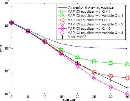
The MAP equalizer, even with a variable-size trellis, is still very costly to implement. In Fig. 7, a simpler simulation setting with QPSK is used to save simulation time. The result verifies that adjusting trellis size does not hurt the performance even when the speed hits 500 km/h. The MAP ICI equalizer with variable-size trellis attains the same BER performance as that of the MAP ICI equalizer with fixed-size trellis (in fact, their BER curves overlap each other), yet the computational cost is significantly reduced. Further reduction of complexity is possible if some techniques reported in recent literatures can be incorporated in the future. It is interesting that for the case when Q ≤ 3, the MAP ICI equalizer performs better than the block MMSE ICI equalizer. It is due to the extra gain provided by combining signals along different ICI paths constructively.
Fig. 7. BER performance comparisons for MAP ICI equalizers under 1024-point FFT, QPSK and ITU Vehicular-A channel model at 500 km/h. Note that the BER curves of MAP ICI equalizers
(solid) overlap that of MAP ICI equalizers with variable size (dash).
2.4 Computational Complexity
We discuss the computational complexity measured in complex floating point operations (flops). The reduction of computational cost in conventional linear ICI equalizers by being incorporated into our per-subcarrier adaptive framework is demonstrated. The low computational complexity of the novel perturbation-based ICI equalizer is also clearly laid out. The complexity of the ICI equalizers comes from calculating equalizer coefficients and applying equalizers. Both aspects benefits from our approach. Only the complexity of calculating equalizer coefficients is considered here for simplicity because it accounts for the majority of the computational complexity. With the same simulation setting, the computational complexity of the block equalizer is approximately 2NA3/3 ≈ 4×10⁸ flops and that of the banded serial equalizer is
approximately NA ×2(2Q+1)3/3 ≈ 7.5 × 10⁵ flops with Q = 5.
Consider the per-subcarrier adaptive framework incorporating serial MMSE ICI equalizers. At the vehicle speed of 350 km/h, according to Table I, 38.9% of subcarriers use one-tap FEQ requiring 0.389 NA flops, 21.8% of subcarriers use 3 × 3 matrix inversion requiring
approximately 0.218 NA ×33 × 2/3 flops, 24.9% of subcarriers use 7 × 7 matrix inversion
requiring 0.249 NA × 73 × 2/3 flops, and 15.4% of subcarriers use 11× 11 matrix inversion
requiring 0.154 NA × 113 × 2/3 flops. Overall, the complexity of the per-subcarrier adaptive
105, which are 22.2% and 14.2% of the number of flops of the conventional banded serial equalizer. In short, for any methods adopting banded approximation, the per-subcarrier adaptive framework can help further computational complexity reduction.
In summary, an informative indicator of ICI level and a per-subcarrier processing framework is proposed; they can work with many existing ICI cancellation methods to reduce the computational complexity and maintain the performance simultaneously. Theoretical analysis and simulations verify our claims. High flexibility is achieved for trade-off between performance and implementation cost.
3. Multiple Carrier Frequency Offsets in Cooperative
Communications
In this section, we address the first perspective of combating synchronization errors with the design of error-tolerant receivers. Notice that we situate our study in the context of utilizing space-time coding, especially Alamouti’s space time block code (STBC) in the distributed (virtual) MIMO scenarios, due to its effectiveness of obtaining diversity gain as well as its low complexity.
As already mentioned, in distributed MIMO systems, each transmitter may have different local oscillators and may not be either frequency or time synchronized, i.e., there exist multiple symbol timing offsets (STOs) and multiple carrier frequency offsets (CFOs) [25]-[30]. It is well known that OFDM systems are sensitive to frequency offsets, and the performance can degrade significantly because of the inter-carrier interference (ICI) due to MCFOs. The resulting superposition of all cooperating nodes’ signal causes standard CFO compensation techniques fail at the receiver. To deal with this problem, various mitigation techniques have been proposed in the literature[25]-[30].
Conventional equalizers can be used to combat multiple CFOs. A time domain equalizer, which aims to maximizing signal to interference and noise ratio (SINR) is proposed for space frequency coded system [25]. A simple method to convert the matrix inversion to a series of small inversions of its diagonal sub-blocks to reduce the calculation complexity is studied in [26]. In [27], several detection and complexity reducing techniques are compared. An ICI-self cancellation scheme at the price of lowering transmission rate is proposed in [28]. A special two branches receiver architecture is proposed in [29]. Based on the iterative inter-carrier interference (ICI) cancellation, a two-step cancellation procedure is developed in [30]. Iterative interference cancellation is yet another popular technique [31]. However, the performance of these techniques
degrades significantly as the magnitudes of MCFOs exceed a mild range.
In this section, synchronization for SFBC-OFDM is studied in the context of cooperative communications with synchronous errors. OFDM is robust to timing errors with a cyclic prefix insertion, so we focus on multiple CFOs. The separate synchronizing architecture in [29] is adopted, but a new SFBC demodulation technique based on [30] is used to increase the resulting SINR. In addition, iterative interference cancellation and a maximum-ratio-combining-like technique is also incorporated to further enhance the performance. The new receiver is computationally efficient and has a superior tolerance range of multiple CFOs and may be suitable for applications in asynchronous cooperative OFDM systems. We also demonstrate, through the time-frequency duality, that our procedure can be applied to combating symbol timing errors in single-carrier systems which is sensitive to this type of synchronization errors.
3.1 System Model
S
R1
R2
D
Source Node Destination Node
Relay Node 1
Relay Node 2
Phase 1 Phase 2
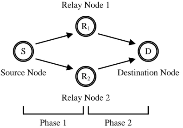
Fig. 8. A typical cooperative communication scenario
Consider a simplified cooperative transmission scheme with one source node, one destination node, and two relay nodes, as shown in Fig. 8. Each node has only one antenna. The decode-and-forward (DF) protocol is adopted [32]. In the first phase, the source node broadcasts the information sequence to the relay nodes. Without loss of generality, we assume that all relay nodes have correctly decoded the information sequence. In the second phase, all relay nodes remap the information sequence and cooperatively transmit it to the destination node.
Assume that a SFBC-OFDM based cooperative system is employed at the relay nodes. All the information sequences use the same signal constellation Γ, such as M-QAM or M-PSK, which can be denoted as X = [X0, X1, …, XQ-1]T. The SFBC-OFDM modulates the symbol on
1 R e l a y 1 R e l a y 2 k o d d e v e n k e v e n o d d f X X f X X (1),
where fk and fk1 are adjacent sub-carriers index. Then the transmitted signal x(n) is
derived from the inverse Discrete Fourier transform (IDFT) of the encoded symbol X(k), }
, {R1 R2
, which can be written as 1 0 1 2 ( ) ( ) exp( ) , 1 N g k j nk x n X k N n N N N
(2),where N is the OFDM symbol length, Ng is the length of cyclic prefix (CP).
A multipath channel model taking into account the effects of multiple oscillators is assumed. The discrete-time baseband equivalent asynchronous received signal can be written as
1 2 1 { , } 0 2 ( ) exp( ) ( ) ( ) ( ) L R R l j n y n h l x n l z n N
(3),where , α{R1,R2}, represents the CFO, which is normalized by the sub-carrier spacing,
between the destination node and the relay node . The l-th path gain profile of the multipath Rayleigh fading channel is denoted as h l( ), L is the number of multipath. In order to avoid
inter-symbol interference (ISI), Ng L should be satisfied. The average total power is
normalized such that
1 2 2 1 { , } 0 [ L | ( ) | ] 1 R R l
E
h l , and z(n) is the AWGN with zero mean and variance ζ2.After removing CP and passing through DFT, the received signals on two adjacent subcarriers are 1 2 1 2 1 2 1 2 0 1, 0 2, 1 1 1 , 1, 1, , 2, 2, 0 0 1 0 1, 1 1 0 2, 1 1 1 1, 1, 1, 1, 2, 2, 0 0 1 1 1 ( ) R R R R R R R R k R k k R k k N N k m R m R m k m R m R m m m m k m k k k R k k R k k N N k m R m R m k m R m R m m m m k m k k Y G H X G H X G H X G H X W Y G H X G H X G H X G H X W
(4),where Hα, α{R1,R2}, and W denote the channel response and complex AWGN in the frequency
domain. Gk m,
is the ICI coefficient, which destroys orthogonality between sub-carriers, caused by multiple CFOs. It can be defined as
1 , 0 2 ( ) 1 exp( ) sin( ( )) 1 exp( ( )( )) sin( ( ) / ) N k m n j n k m G N N m k N j m k N m k N N
(5), When k=m, Gk m, can be simply defined as G0
. Here, the perfect CSI known at the destination node is assumed.
3.2 Multiple CFOs Mitigation
We take cues from the two-step ICI cancellation algorithm for SFBC-OFDM [30] and the two-branch MCFOs mitigation algorithm [29]. Both methods are designed for asynchronous cooperative systems. However, they can only achieve near Alamouti performance with moderate range [max max], in which max 0.2 and the performance degrades rapidly if the MCFOs
go beyond the range. We proposed a new SFBC decoding algorithm by better using the separately synchronized signals to extend the tolerance range of multiple CFOs. The detailed mitigation algorithm is described as follows.
As in [29], assume that the receiver can estimate multiple CFOs separately and have multiple copies of the received signal compensated for each CFO. For example, preambles which are orthogonal to each other for each relay node may be used to facilitate the estimation of CFOs. Before DFT, the compensated signal can be express as
( ) exp( 2 ) ( )
y n j
n y n (6), where 0 ≤ n ≤ N-1 and α{R1,R2}. Then, for SFBC, the two sets of separately synchronizedsignals in the frequency domain can be written as YR1( )n DFT y
R1( )n
and
2( ) 2( )
R R
Y n DFT y n .
The new SFBC decoding algorithm is modified from the one found in [29] while the major difference is that our algorithm processes two sets of separately synchronized signal jointly, inspired by the method found in [33]. The principle is illustrated in Fig. 3.
Sync. R1-D Link Sync. R2-D Link FFT FFT 2 1 1 2 1, 0 2, 2, 1 ( 0 1, 1) R R R R H R k R k R k R k H G H H G H 1 2 2 1 0 1, 2, 0 2, 1 1, 1 ( ) R R R R H R k R k R k R k G H H G H H Received Signal Decision Direction + Selection 1, R k Y 2, 1 R k Y 2, R k Y 1, 1 R k Y 1 ˆ k X 2 ˆ k X 2 1 ˆ k X 1 1 ˆ k X ˆ k X 1 ˆ k X ICI Cancellation
Fig. 9. The block diagram of the receiver with the proposed MCFOs mitigation algorithm
From Fig. 9, we can see that there are two signal sets going into the decision block. Due to synchronization errors, neither of the two signal sets obtained by the SFBC decoding is absolutely better than the other. Signal detection adopts the Minimum Euclidean distance decision rule, as is in [29]: the decoded signal with smaller decision error will be deemed as more reliable and selected. The detection rule can be expressed as
ˆ a r g m i nˆ i k k i d X (7),
Alternatively, to show that the two signal sets indeed possess information to further improve SINR, we propose an ad hoc method which mimics Maximum Ratio Combining (MRC) to combine the two signal sets. Express the signals in a short hand notation:
1 1 2 2 1 1 2 2 ˆ ˆ ˆ ˆ ˆ k k k k k k comb k k k k k X X X X X w X w X (8), where 1k and 2 k
are interference plus noise terms The weights w and 1k
2
k
w on the k-th
subcarrier are chosen to “maximize” the SINR. Typical MRC solutions are obtained from the optimization problem: 2 minimize subject to 1 H k k H k w Ξ c w , (9),
in which Ξk [ 1k 2k]T, wk [w1k wk2]T and c[1 1]T , whose solution is -1 Ξ k H -1 Ξ R c w c R c .
Due to the fact that the interference-plus-noise terms are unknown, we opt to an ad hoc method to calculate w . First, all possible noise-plus-interference terms are calculated by treating every k
constellation points as candidate decisions. Then the minimum decision errors in each signal set are selected as the instantaneous noise-plus-interference terms. Then the combining coefficients are obtained via the ratios of instantaneous SINRs. Finally, the decision is made on the combined signal to get dˆk.
A parallel interference cancellation (PIC) scheme at each sub-carrier finally is added to complete the receiver. Within an iteration, the symbol decisions are used to reconstruct the ICI due to signal spilling from one subcarrier into another. The ICI cancellation operation can be expressed as 1 2 1 1 ( ) ( 1) ( 1) , 1, 1, , 2, 2, 0 0 0 ˆ ˆ 0 R R k N N r r r k k k m R m R m k m R m R m m m m k m k Y r Y Y G H X G H X r
(10) where ˆ( )1 r R X and ˆ( )2 r RX represent for the symbol decisions of the r-th iteration with the minimum Euclidean distance criterion. As the iteration number increases, more precise estimates of the transmitted symbols can be obtained.
3.3 Time-Frequency Duality and Single-Carrier Systems
Alamouti STBC is a well known transmit diversity scheme for flat fading channels. Since the cooperating nodes are physically separated, the different respective clocks lead to asynchronous transmission and reception. Therefore, the ISI appears and the performance degradation is caused by the non-orthogonal space-time combination. Thanks to time-frequency duality, which ISI caused by STO can be viewed as a time-domain version of ICI, our proposed method is also applicable to single-carrier transmission in the presence of ISI up to a large error range, e.g., ΔTmax = 0.625 Ts, as verified in numerical simulations.
Without going into details, we will summarize the ISI-mitigation steps for single-carrier systems as follows.
a) The receiver needs to register four values from two separately sampled sequences for one Alamouti block of two transmitted symbols.
b) Perform two sets of modified Alamouti space-time decoding to reconstruct the nearly orthogonal STBC.
c) Select the more reliable decoded signal through minimum Euclidean distance decision. Apply iterative Interference cancellation.
3.4 Simulation Results
In this section, we show some simulation results to demonstrate the performance of the proposed scheme for an uncoded cooperative Alamouti SFBC-OFDM system with two relay nodes. The channel used is a four equal gain multipath Rayleigh fading channel (the channel taps are uncorrelated complex Gaussian random variables with zero mean and normalized variance
1/2). Other simulation parameters are listed in TABLE II.
TABLEII SIMULATION PARAMETER
Channel Model Rayleigh Fading Power Delay Profile Uniform
Number of Taps 4 Number of Subcarriers 512 Cyclic Prefix 32 Type of Modulation QPSK Number of Total Simulated Frame 100000
Fig. 10 depicts the BER vs. bit signal-noise-ratio (Eb/N0) of the proposed scheme with
synchronous impairments. To show the tolerance range to large multiple CFOs, the normalized multiple CFOs are set to be R1= 0.25 andR2= -0.25. The performance is poor without iterative ICI cancellation. With iterative ICI cancellation, the performance improves, and the full diversity order is achieved. It is also shown that the MRC-like operation can further improve the SINR and the BER approaches the theoretical bound.
0 5 10 15 20 25 10-5 10-4 10-3 10-2 10-1 100 BER Eb/N0 Without ICI Cancellation 1st Iteration (Selection) 5th Iteration (Selection)
5th Iteration (MRC-like sum + Selection) Theoretical Lower Bound [13]
Fig. 10. BER performance with the relative CFO = 0.5
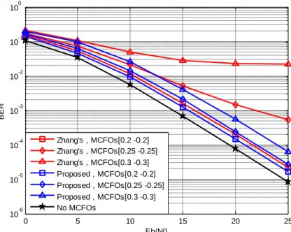
Fig. 11 compares the performance of our algorithm and Zhang’s method in [31]. In both cases, iterative ICI cancellation is applied. Zhang’s method works fine when multiple CFOs is
less than [0.2 -0.2], but degrades significantly and error floors appear as MCFOs get larger. On the other hand, our proposed receiver maintains the diversity order with a small SNR loss compared to the case with no MCFOs; this confirms that the degradation caused by MCFOs can be effectively reduced even when the offset is large. The effect can be ascribed to the fact that ICI and ISI may be largely eliminated at the SFBC decoding stage.
0 5 10 15 20 25 10-6 10-5 10-4 10-3 10-2 10-1 100 BER Eb/N0 Zhang's , MCFOs[0.2 -0.2] Zhang's , MCFOs[0.25 -0.25] Zhang's , MCFOs[0.3 -0.3] Proposed , MCFOs[0.2 -0.2] Proposed , MCFOs[0.25 -0.25] Proposed , MCFOs[0.3 -0.3] No MCFOs
Fig. 11. BER performance comparison between Zhang’s method and the proposed algorithm under different multiple CFOs
0 0.1 0.2 0.3 0.4 0.5 0.6 0.7 0.8 0.9 1 10-5 10-4 10-3 10-2 10-1 100 |εR1-εR2| BER Eb/N0=10dB Eb/N0=20dB
Fig. 12. BER performance vs. relative CFO |R1R2|
Fig. 12 illustrates the BER performance vs. the relative CFO |R1R2|with Eb/N0 = 10 and
20dB. The increase of relative CFO hurts the performance eventually. However, the Alamouti diversity order can be maintained up to when the relative CFO is 0.6. This shows the superior tolerance to multiple CFOs by deploying our proposed decoding algorithm.
In summary, the performance of distributed SFBC-OFDM systems with the presence of multiple CFOs is studied. A new SFBC decoding algorithm is proposed for cooperative systems to combat multiple CFOs. Iterative interference cancellation is used to further mitigate the ICI and reduce the error floor. Simulation results show that the proposed algorithm is effective for asynchronous cooperative systems. The algorithm has a moderate computational complexity and a superior tolerance range of multiple CFOs, compared to existing techniques. Extension to single-carrier systems with multiple STOs is also outlined.
3. BICM-OFDM to Combat Multiple Synchronous
Errors
In this section, we move on to the second perspective of combating synchronization errors in cooperative MIMO communications. We will view the synchronization errors, not as impairments which cause performance degradation, rather as potential sources of diversity gains. Through careful design of a BICM-based scheme and an iterative receiver, it will be shown that dramatic increase of diversity gain is actually achieved when severe synchronization errors exist.
3.1 System Model
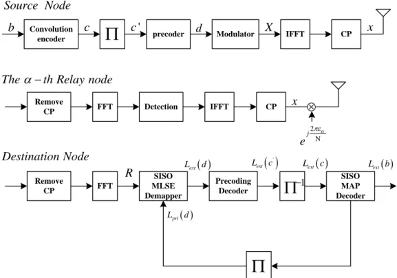
We adopt the decode-and-forward protocol for this section, and BICM-OFDM [24] are chosen as the transmission technique. Fig. 13 shows a generic block diagram of a system employing BICM-OFDM, at the source side the information bits denoted b are first encoded by the outer convolutional encoder and the encoded bits are denoted by c∈C, C being the codeword set. The interleaver ∏ operates on K OFDM symbols of encoded bits with the output denoted by
c’, then the inner differential precoder with recursive structure [34] is deployed to enhance overall performance and its output is denoted by d. The resulting bits are mapped into QAM or PSK symbols. The set of constellation points is denoted by χ, as γ bits are mapped into one of 2γ constellation points according to the mapping rule. After loading the modulated symbols onto active subcarriers, OFDM signal x is generated via N-point IFFT and CP is inserted. The performance depends on the size of interleaver that is γKN bits. Note that the encoded bits are interleaved across several OFDM systems and it is called time-frequency interleaving. The time-domain transmitted signal at Relay Node α can be written as
2 1 0 1 , - - 1 nk N j N g n x k n e N k N N
X (11)the length of CP, k is the sampling index, α∈{1,2,..,M} is the relay node index, and M is the number of relays. Assume the CP is longer than the largest channel delay spread plus timing error so that ISI can be ignored.
Convolution
encoder
precoder Modulator IFFT CPb c c' d X x
Source Node
Theth Relay node
Remove CP x FFT Detection IFFT CP Destination Node Remove CP FFT SISO MLSE Demapper 1
Precoding Decoder SISO MAP Decoder
pri L d extL d Lext
c' Lext c Lext bR 2 N j e
Fig. 13. The block diagram of the proposed scheme for asynchronous cooperative communications
Time varying multipath Rayleigh fading channels are considered, and the discrete time baseband equivalent received signal at the k-th sampling time can be expressed as
2 1
1 0 , k M j L N l y k e h k l x k l z k
(12) where εα and ηα represents the normalize CFO and the timing error between destination node andthe α-th relay node. Let hα(k,l) represents the l-th path gain of the multipath Raleigh fading
channel from the α-th relay to the destination. The wide-sense stationary uncorrelated scattering (WSSUS) channel is assumed with
2[ H , , ' ] h ( ) ( ')
E h k l h m l r q ll
(13)
where h2 denotes the variance of the l-th tap gain with normalized average power
2 1 2 1 1 1 [ M L , ] M h 1 l h h l
, L is the number of multipath, r(q) denotes the normalized tap autocorrelation ( r(0)=1 ), and δ(l-l’) is the Kronecker delta function. Moreover, assume the paths
0
( ) (2 ( ) )
r q J f km T
(14)
where J0(〃) denotes the zero-order Bessel function of the first kind and f is the Doppler
frequency of the α-th relay node, T represents one OFDM symbol time, xα(k) is the transmitted
signal of the α-th relay node, and w(k) is additive noise, which is independently and identically distributed (i.i.d.) complex Gaussian random variable with zero mean and variance z2. Consider
the model in frequency domain by taking the N-point DFT to y(k) in (2). The p-th OFDM symbol in the frequency received signal can be written be
, , 1 , , 1 , 1 ( ) , 1, 2..., H p M H p p p p M p p p p M p p p y k p K
R F F E H FX Z T G X Z G X Z (15) where [ p, p 1,..., p 1] T p N N N N R R R Ris an N×1 frequency domain receiver vector, Np=(p-1)N
denotes the starting index of each OFDM symbol, F1 / Nexp{ 2j nk N/ } is N×N the IDFT matrix with (n,k), the entry [ ]Fn k, 1 / Nexp{ 2 (j k1)(n1) /N}, n = 1, 2, …, N, X
p = FHx(k) and Zp =
FHz(k) are the frequency domain transmitted data and additive noise, respectively, where Xp and
Zp are an KN×1vector. Since FFT is unitary, the entries of Zp are still white complex Gaussian
variables with mean zero and variance 2z.
3.2 The Receiver Algorithm
For the receiver, both MSE and MLSE equalizers can be used. Here we focus on the design of MLSE receiver in the frequency domain and the overall receiver. The iterative receiver consists of a Soft-Input Soft-Output (SISO) MLSE demapper/equalizer and Maximum A Posterior (MAP) decoders for both the precoder and the convolutional encoder. The soft outputs are typically represented by the log-likelihood ratio (LLRs). The signal detection in the demapper/equalizer is carried out with MLSE.
The task of the equalizer is to estimate the transmitted X based on the received observations
R. more specifically, the maximum likelihood sequence estimation is to choose that sequence of
symbols X={x1,x2,…,xK} that maximizes the likelihood of the received sequence of observation
sequence is the optimal solution and procedure is referred to as MLSE. There exist basic approaches to implement an MLSE equalizer in [35].
Start with the states at the k-th stage of the associated trellis diagram that are related to the Q-1 most recent transmitted symbols, i.e.,
1 1
( , ,..., ,..., )
N N N
k D k D k k D k
s x x x x (16)
Thus, each state corresponds to one of the 2γ(Q-1) possible vectors that can be formed from Q-1 symbols. There are 2γ allowable transitions that emerge from a state sk and terminate at 2γ
different states sk+1, leading to a total of 2γQ transition branches connecting two successive states
(sk→sk+1). Each transition is associated with a cost, contributing to the total cost of a path along
the states. The cost of the i-th transition between sk and sk+1 exists transition probabilities is
called a branch metric, connecting two specific consecutive states (sk→sk+1), is given by
2 1 2 1 ( ) | | 2 i k k k z s s R GX (17)
Notice that each state has 2γ incoming branches except a few stages in the beginning and in the end. Each incoming branch is due to the advent of a new symbol. Of the 2γ incoming branches, only the one connected, and the new symbol metric Γ(sk) is calculated that formulation
represent ' ' 1 1 ' 1 ( ) ( )+ ( ) pri ( n) n( ) k k i k k MLSE k n s s s s L d x
(18)where LMLSEpri ( ) is priori bit LLRs by the SISO outer decoder and λn’(x) is represent the constellation point x of the value at the n’-th bit. That retained path is referred to as survivor path. After all states of the trellis have been gone through, the smallest state metric be found and trace back that the ˆx is obtained.
A soft decision as the log-likelihood ratio is obtained by ˆ ( 1 | ) ( ) ln( ˆ ) ( 0 | ) k k k P d L d P d R R (19)
Thus MLSE output bit LLRs is transformed by symbol metric.
1 0 ( ) ln ( ( ) | , ) ln ( ( ) | , ) ( ) n n n MLSE k pri n MLSE k L d P k P k L d
X X R G X R G X , (20) where dkn represent n-th bit at k-th transmit subcarrier is mapped,n b
represent constellation
point set of n-th bit is b ∈{0,1}.The inner and outer decoder are adopting a maximum a posterior probability (MAP), output are the bit log likelihood ratio and log-MAX algorithm is usually applied for lower computational complexity. A trade-off between complex and performance can be achieved by different choices of D, K, and γ.
The computational complexity of MLSE is 𝒪 (IN2Q
) where I is number of iteration and for the MMSE receiver it is 𝒪 (N3
) in one OFDM symbol. The MLSE is much more expensive than the MMSE receiver when high order modulation or large D is used.
3.3 Simulation Results and Discussion
To demonstrate the effectiveness of the MLSE receiver, Monte Carlo simulations are carried out, and we compare the Bit Error Rate (BER) performance between the MLSE equalizer and MMSE equalizer. Notice that both receivers effectively harvest the extra diversity gain provided by synchronization errors.
We consider a BICM-OFDM system with N = 64, CP length = 8, and 4-QAM modulation. A two-path wide-sense stationary uncorrelated scattering (WSSUS) Rayleigh fading channel (generated using Jakes Model) between any relay nodes and each relay are equal power, the convotional code uses G(D)=(1+D2,1+D+D2) as the generator polynomial, and G(D)=1/(1+D2) is the generator polynomial for the precoder. One frame consists of 10 OFDM symbols. Furthermore, perfect estimations of MCFOs and channel matrices are assumed.
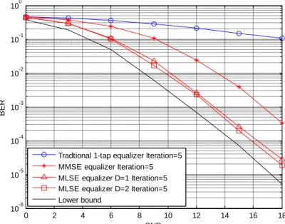
Fig. 14 shows the BER performance versus SNR for the comparison between conventional MMSE equalizer, traditional 1-tap equalizer and the MLSE equalizer in synchronous impairments. For the simulation, normalized Doppler frequency fd=0.001 is employed at both relays, the normalized MCFOs are 0.2 and -0.2. With the large MCFOs, the 1-tap equalizer suffers an obvious error floor.
0 2 4 6 8 10 12 14 16 18 10-6 10-5 10-4 10-3 10-2 10-1 100 SNR BER
Tradtional 1-tap equalizer Iteration=5 MMSE equalizer Iteration=5 MLSE equalizer D=1 Iteration=5 MLSE equalizer D=2 Iteration=5 Lower bound
Fig. 14. BER comparison between MMSE equalizer, 1-tap equalizer and MLSE equalizer in the cooperative communication
On contrast, the MLSE equalizer not only successfully compensates for the ICI but also obtain an SNR gain about 3dB. The benefits of SNR gain, we can via SINR to explicit explanation and the derivation in appendix. The optimal solution is joint processing of demodulation and decoding is considered, which lead to approach low bound. Notice that with both equalizers the system achieves full diversity.
Fig. 15 shows the results for the two relay nodes and three relay nodes. It can be seen from the figure that as the number of relay increases in the systems, the diversity order of distributed BICM-OFDM increases up to the maximum diversity of min{M×rT×L,dfree}. It can be observed that the tree relays case has a diversity order of 5 and the BER curve is steep.
0 5 10 15 10-5 10-4 10-3 10-2 10-1 100 SNR BER M=2, CFOs=[0.2 -0.2] Iteration=5 M=3, CFOs=[0.2 0 -0.2] Iteration=5
Fig. 15. The BER curves compared with difference number of relay nodes
In Fig. 16, all the realistic synchronous impairments are considered. The timing errors is [0 3], normalized Doppler frequency is 0.1 for both relays and MCFOs is [0.2 -0.2]. In our proposed the performance show efficiently collects the diversity form time diversity due to the Doppler effect, frequency diversity due to timing error and special diversity converted to time diversity due to MCFOs. It observed that the diversity is more than four.
0 2 4 6 8 10 12 14 16 18 10-5 10-4 10-3 10-2 10-1 100 SNR BER
CFOs=[0.2 -0.2] Fd=0.001 Timing error=[0 0] CFOs=[0.2 -0.2] Fd=0.1, Timing error=[0 3]
Fig. 16. The BER for cooperative communication under time error = [0 3], normalize Doppler frequency = 0.1, MCFOs = [0.2 -0.2]
In summary, BICM has the potential to improve performance with relatively ease in many OFDM wireless communication systems. It is shown that, with proper receiver design, the BICM-OFDM can be effective to combat synchronous errors as well as harvest potential diversity gain in cooperative communications. Typical BICM-OFDM systems suffer error floors due to ICI caused by MCFOs and Doppler effects. To deal with such a problem, we propose an
MLSE-based frequency domain equalizer combined with a turbo decoder to break the error floor. The proposed approach has excellent BER performance, and it is flexible in a way that extension to more relays for improvement in diversity gain is straightforward. The complexity is a big problem in the receiver if D is greater than three, and future research in the complexity reduction will be considered.
4. 結果與討論
寬頻合作式無線多輸出入通訊系統如果運行在一高速移動環境中,因都普勒效應及多 重同步誤差所造成的通道衰落及載波間干擾問題,將造成嚴重的系統效能損失,大大地降 低了這類方法的實用性。在高速移動問題方面,我們探討了載波間干擾問題,瞭解到具成 本效益與良好表現的方法仍為業界急需,我們從實用角度出發,重新檢視現有方法的侷限, 並提出新的解決方案,同時我們的通道模型也非常適合寬頻合作式無線多輸出入通訊系統 的通道估測需求。 在同步問題方面,合作式通訊系統和一般習見的情況有所不同、同步問題在傳送端便 已存在。互相合作形成天線陣列也許分散在極為不同的傳輸環境中,因而無法像傳統處於 同一地點的傳送天線陣列達成載波頻率及符元時間的完全同步。本計畫預計經由兩個面向 提出同步問題的解決方案。首先我們從設計接收機著手,我們考慮廣泛使用的阿拉木提多 輸出入系統,為其設計一套對同步誤差具有超強容忍力的接收機,數值模擬結果表明它運 用於單載波系統可抵抗極大的載波頻率誤差,運用於多載波系統則可抵抗極大的符元時間 誤差。 其次、我們也從編碼設計的角度解決同步問題。在這裡,我們不將同步誤差視做必須 避免的問題,反而視為多集性增益的可能來源。經由為合作式多輸出入通訊設計一種位元 交錯編碼調變方式,我們發現、當同步誤差存在時、多集性增益竟大幅增加,我們也對此 結果做了一些理論分析。至此、在 Alamouti 編碼以及 BICM 的情況下之同步問題,已獲得 解決。5. 計劃成果自評
總結我們的技術成果,在於解決合作式通訊(分散式多輸出入系統 distributed MIMO)在 搭配 Alamouti 編碼或是 BICM 的情況下之同步問題,以及高速移動下可能面臨的載波間干 擾問題。我們提出一個可評估載波間干擾嚴重性並隨時調整的處理架構,有效降低了運算 成本,確實為業界所需之實用性技術。我們也發展了兩套傳輸架構,兩者皆有極佳的同步誤差容忍度,在文獻中尚未見到有可和我們比肩的結果。我們認為,這項成果,對合作式 多輸出入系統的實用化有很大的意義,唯目前開發的接收機演算法仍具高複雜度,降低運 算複雜度我們努力的方向。 在論文發表方面,累計相關國際會議論文發表五篇(其中兩篇與林大衛教授合 作)[36]-[40],已有三篇會議論文轉為期刊論文投稿,但過程未如人意,目前尚在審稿中。
6. 參考文獻
[1] 最新標準資料可在 http://www.3gpp.org/ftp/Specs/latest/ 下載.[2] WiMAX Forum, Mobile WiMAX — Part I: A Technical Overview and Performance
Evaluation. WiMAX Forum White Paper, Aug. 2006.
[3] IEEE Standard for Local and Metropolitan Area Networks – Part 16: Air Interface for
Fixed and Mobile Broadband Wireless Access Systems – Multihop Relay Specification.
[4] R. Irmer et al., “Coordinated multipoint: concepts, performance, and field trial results,”
IEEE Comm. Magazine, pp. 102-111, no. 2, Feb. 2011.
[5] W. G. Jeon, K. H. Chang, and Y. S. Cho, “An equalization technique for orthogonal frequency-division multiplexing systems in time-variant multipath fading channels,” IEEE
Trans. Commun., vol. 47, no. 1, pp. 27–32, Jan. 1999.
[6] A. Stamoulis, S. N. Diggavi, and N. Al-Dhahir, “Intercarrier interference in MIMO OFDM,” IEEE Trans. Signal Process., vol. 50, no. 10, pp. 2451–2464, Oct. 2002. [7] X. Cai and G. B. Giannakis, “Bounding performance and suppressing intercarrier
interference in wireless mobile OFDM,” IEEE Trans. Commun., vol. 51, no. 12, pp. 2047–2056, Dec. 2003.
[8] A. Gorokhov and J.-P. Linnartz, “Robust OFDM receivers for dispersive time-varying channels: equalization and channel acquisition,” IEEE Trans. Wireless Commun., vol. 52, no. 4, pp. 572–583, Apr. 2004.
[9] P. Schniter, “Low-complexity equalization of OFDM in doubly selective channels,” IEEE
Trans. Signal Process., vol. 52, no. 4, pp. 1002–1011, Oct. 2004.
[10] I. Barhumi, G. Leus, and M. Moonen, “Time-domain and frequency-domain per-tone equalization for OFDM over doubly selective channels,” Signal processing, vol. 84, no. 11, pp. 2055–2066, 2004.
[11] Y. Mostofi and D. C. Cox, “ICI mitigation for pilot-aided OFDM mobile systems,” IEEE
Trans. Wireless Commun., vol. 4, no. 2, pp. 765–774, Mar. 2005.
[12] L. Rugini, P. Banelli, and G. Leus, “Simple equalization of time-varying channels for OFDM,” IEEE Commun. Lett., vol. 9, no. 7, pp. 619–621, Jul. 2005.