Proceeding of the 2004 American Control Conference
Boston, Massachusetts June 30 -July 2,2004 ThM05.6
Novel Integrated Management System Design
of
Electric Motorcycles
Su-Hau Hsu', De-Wei Hsu', Li-ChenFu"*
and Yu-Po Hsu''Department of Electrical Engineering
'Department of Computer Science and Information Engineering National Taiwan University, Taipei 106, Taiwan, R.O.C.
Email: lichen@ntu.edu.tw Abstract- In view of the need for effective usage of the
battery energy of the electric motorcycle, we propose un integrated management system, which not only accom- plishes the objective of robust velociry tracking but also efficiently utilizes the stored energy of the battery. This integrated management system is divided into three major subsystems, including the power-saving controller, energy supervisor and protection subsystem. The concept of intel- ligent decision is applied such that the redundant energy loss can be avoided. At the end, simulation andexperimental results will be given to demonstrate the feasibirily and va- lidity of the proposed integrated management system. Keywords: Electric motorcycles, integrated manage- ment systems, DSP-based control.
1. INTRODUCTION
The major bottleneck in popularizing the electrical motor- cycle (EM) is exactly the energy density of the battery. Al- though the battery technology developed in the world is gradually improved, the energy density is still not sufficient enough for mobile vehicles and it makes the user akaid of
exhausting all of the battery energy before the arrival at the destination. Hence, an integrated management system with overall system dynamics, modeling, controller with power-saving strategy, energy supervisor with energy reuse, and hardware protections for the EM is of great urgency.
To concem traction control of vehicles, Kimbrough [I]
has presented a method to enhance the stability and traction of a road vehicle during acceleration or braking. However, the knowledge of the friction coefficient and the slip ratio is the most dominant key point of the traction control. There- fore, Germann et al. [ 2 ] have proposed a friction monitoring system that utilizes recursive least squares estimation. Moreover, Sado et al. [ 3 ] have proposed a mction control system for the electric vehicle that includes an optimal slip control scheme with a driving-force observer to detect the road friction coefficient and a fixed-trace algorithm to es- timate the slop of the slip ratio curve. As to the overall sys- tem analysis and controller design of the EM, Lin and Fu [4] have established a suitable dynamic model and used the feedback linearization for the velocity tracking control. With regard to the energy management system design, Pavlat et a1
[SI
proposed an Energy Management System (EMS) to monitor and record the State of Charge (SOC) ofthe battery,vehicle performance, power consumption of the key com- ponents, and user's actions. And, it is implemented by a microprocessor-based electronic module and then modifies the inefficient energy use to extend the usable driving range and the life of the battery pack. Moreover, Jalil et al. [6] have accomplished a rule-based energy management strat- egy for a series of hybrid vehicles.
In this paper, we propose a novel integrated management system for the EM and the major viewpoint is on the highly efficient energy usage. Moreover, this management system is realized by a TI DSP F240 EVM platform and a proto- typing EM to verify and illustrate the feasibility and validity of the integrated management system.
2. MODEL ANALYSIS
By the analysis of the EM, we have investigated the rela- tions between the input and output, dynamic or static be- haviors of each part of the EM system in detail and the block diagram of the EM can be established as shown in Fig.]. Afterwards, the overall dynamic model of the EM system is derived as follows:
6, =-am, -bNlp(A)+cV, -&, (1)
where
J , = J + n : n i J , , Ed, = B+n:n:B, +n,n,niJ, where w, is the motor velocity, NI is the normal force ofthe driving wheel, PO,) is the road Giction coefficient with A
being slip ratio, V, is the input voltage, ~b is the braking
torque, v is the vehicle velocity, A4 is the total mass of the EM, including the rider's weight, c, is the coefficient of
aerodynamic resistance, 5 is the coefficient of rolling re-
sistance, a is the angle of inclination, R, is the motor re- sistance, K, is the torque coefficient, K, is the electrical coefficient, r is the radius ofthe wheel, n, is the transmission ratio of the continuous variable transmission (CVT), nz is the gearbox with a fixed transmission ratio, J is the moment inertia of the motor, i( is the damping coefficient of the motor, J, is the moment inertia of the driving wheel, and B, 0-7803-8335-4/04/$17.00 02004 AACC
is the damping coefficient of the driving wheel. The motor inductance L, is neglected here. Note that Eq. (1) describes the dynamics of the brushless DC motor (BLDCM). And Eq.
(2) gives the dynamics of the vehicle velocity with the outer environmental effects such as the resistances, climbing angle, and the slip phenomenon. And, it is derived according to Newton’s law.
3. MANAGEMENT SYSTEM DESIGN The proposed management system of EM is shown in Fig. 2,
including the power-saving controller, energy management, and hardware protection subsystem.
3.1 Power-Saving Controller Design
The architecture diagram of the power-saving controller is illustrated in Fig. 3, including a sliding-mode and a fuzzy controller. In order to attain a fast tracking response, we adopt the sliding-mode control to achieve that. And, in order to realize the power-saving concept, we use the fuzzy con- trol to modify the output voltage of the sliding-mode con- troller based on the instantaneous information of slip ratio.
Fuzzy controller: The fuzzy controller is one SISO sub- system, where the main idea is “The larger the slip ratio, the smaller the f i z z y weighting”. We utilize the center ofgrav- ity method to transfer the fuzzy sets to the desired crisp value. The membership functions of slip ratio h and fuzzy weighting kfi are shown in Fig 4, and the fuzzy tule is listed
in Table 1.
Sliding-mode controller: The sliding-mode controller developed is to perform the velocity of the EM. Our goal here is to design a robust controller such that the zero con- vergence of the tracking error as time tends to infmity can be guaranteed, i.e., the tracking error e = v - vd goes to zero asymptotically. Substituting Eq. (1) into Eq. (2) yields:
1 c v z
Mb M
v=-(ckfiV,
-6,
-awe - d r , ) - i - - a g c o s a-
g sin a:where we have considered the modified voltage by the fuzzy
controller. The sliding surfaces is defined as s = v
-
vd (= e)such that:
1 e v2
3 = -(ck, V, -ha
-
aw,)-
-
agcosa-
gsin a - CdA43 M
The control law is designed as follows:
1
-
Mb c,v=
(3) V, =-(am,
+
0,)
+-[-+ g sinh
+ a g cosh
+ i dC c M
- K , sgn(s)-K,sl,
where the constant Kp > 0, the adaptive law of KO is
k,
= kfi1sI, the nominal value of a ish
, and the measured data of be is b e . Thus, the dynamics of 3 becomes as follows:-
i = D - K , k , sgn(s)-K,kfi,s, (4)
where the disturbance
5
is considered as:c
- 1
D
=-
Mb [ a w ( k f ,-
1)+
(k,&, -w
,
)]+
[ L M v z (kf, - 1)+g(k, sin&-sina)+og(k,, C O S & - C O S ~ ) +v,(k, -I)].
Stability Analysis: We choose the Lyapunov-like function as:
1 1
V = - s * + - ( K , 2 2
-K:)z
whose time derivative can be evaluated as:
k
<-K,kfis’ - K:k,( S I
+
15
11sI.
Thus, if K:kfi tI
5
I
,
we have:V<-Kpkfis2 -qlsl, (5)
where q = K,‘kfi-
1
5
1
is a positive value, which means that this control law achieve the zero convergence of the sliding surface as time tends to infinity, i.e., v - vd+
0 as f --f m[7].
It is worth noting that there may be a realizable issue due
tf he proposed control law (3), i.e., can we actually acquire ha by the measureme?t of
6,
?Thanks to the current technology in filtering, this term b, can indeed be obtained though filtering the differencedw,
by both ana!og LPF and digital FIR filter coded in DSP chip. It is found that he is a reasonable approximation ofhe in our case, whereby Eq. (3) can be implemented. Moreover, one may ask a question, i.e., can the sliding-mode controller save the power? Theoretically, it cannot. However, the purpose that we use this controller is to obtain a fast re- sponsive performance and its robustness.
So,
in
order to avoid the chattering that may waste the energy, we will utilize two methodologies to alleviate it. One is to replace the sign function sgn( .) with a saturation function sat( .), and the other is to switch off the adaptive law, which is designed for the sliding gain as shown in Eq. (3), when the tracking error is under a critical level. Besides, the drift of the adap tive sliding gain will also be avoided following the modifi- cation by means of leakage term [8].3.2 Energy Management Subsystem Design
When riding an EM, all the power energy comes 6om the battery, and thus, we develop an energy supervisor to manage all of the events about the energy consumption. We focus on two major subjects. One is the energy indicator, which needs to monitor the state of charge, whereas the other is the regenerative braking operation, which needs to reuse the energy.
Residual capacity estimator: In order to get the initial SOC
of the battery, we gauge the open-circuit voltage (OCV) and then utilize the relation between the SOC and the OCV to get the initial value. This method is suitable for static-state but not for dynamic-state estimation due to the battery characteristics. Hence, we then use the Ampere-hour inte-
gration method [9] to calculate the output energy, including the consumed energy AhAHl outside the battery due to the load, and the dissipated energy AhTR inside the battery due to the internal resistance which is a function of time. There- fore, the residual capacity can be presented as
A h r e d u d = Ahmmd - - (6)
However, in order to take the estimation error into account due to the environmental effects, such as the operating tem- perature, times of usage, age effect, and so on, we prefer to estimate the residual capacity more conservatively to avoid exhausting all the battery energy. So that, we update the initial capacity based on Eq. (7) after a time interval,
(7) where Ah,.,,znl, r(~vocv) is the energy capacity obtained by the OCV method and Tstands for the operating period fiom the EM velocity v > 0 to v = 0. From Eq. (7), we can see that we update the next initial capacity based on the previous re- sidual capacity we have estimated and the present initial capacity by OCV method. The flowchart for estimating the residual capacity is depicted in Fig. 5.
Regenerative braking system: Theoretically, we can ap- propriately control the gating signals of the inverter to achieve the regenerative braking. According to a simple but feasible method by the Taiwan UQM Electric Co., as soon as the EM is braking, we then use a fixed duty ratio to be this switching control scheme. However, this fixed duty ratio should be pre-decided according to the ability of the inverter to avoid the damage. Obviously, the regenerative current dynamics is too complex to be derived due to the simple method we have used so that no analytic form is presented here. Even so, we still can obtain the reusable energy AhRG by the Ampere-hour integration method, in which the “current” term is measured directly. Finally, we have to modify the updated initial capacity as shown in Eq. (8) because of the obtained regenerative energy Ah&
Ahrss,b,,r = m i n f A h ~ ~ ~ ~ ~ ~ , ~ - , - A h n ” , ~ ~ ~ y o c v ~
1,
Ahmttzal,T = Ahznrhd,T
-
AhRG. (8)3.3. Proteetion Subsystem Design
In this protection subsystem, we provide three major functionalities, including the over-heat for the BLDCM, over-current for the power driver and the over-discharge protection for the battery. The fvst two are achieved by the hardware circuit and send the interrupt signals to DSP for warnings. The third one is developed for the batter to avoid the over-use situation, which may cause the damage of the internal structure of the battery. The protection strategies are illustrated in Table 11. Notice that obviously the protections do achieve the goal, but it also directly limits the perfoxm- ance of the EM. It immediately imposes effects on the rider’s feeling and then may degrade the speed-following performance ofthe EM. For this consideration, we decide to leave this protection to he optional according to the rider’s preference.
4. SIMULATION RESULTS AND DISCUSION
In
system can achieve the goal, we utilize the MATLAB SIMU-
LINK s o h a r e to simulate the closed-loop system. Parame- ters of the EM used here are given by empirical exercises and Taiwan UQM Electric Co.
4.1 Power-Saving Controller
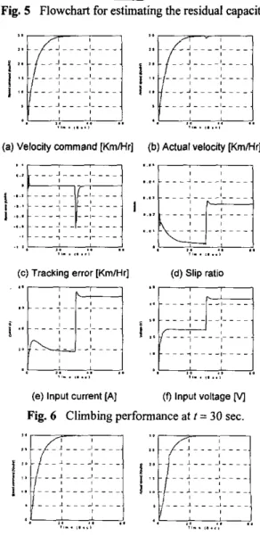
Robust tracking performance: The following case is considered: The EM is grading while the simulation timet =
30 sec, a =
IO
deg., and the total simulation period i s 60 sec. The simulation results are shown in Fig. 6. Before the EM is grading, the maximum tracking error is about 0.2 km/hr. However, as soon as climbing starts, the output power rises up rapidly in order to maintain the tracking performance. Although the error has instantly increased, it remains less than 0.8 Km/Hr and converges back to zero in a short time. The robustness of the sliding-mode controller is clearly exhibited.Power-saving performance: We simulate the EM travelling on an inferior road condition to present the power-saving performance. By the way, in order to illustrate the power-saving capability we’ll use the proposed residual capacity estimator here, so it wouldn’t be illustrated again in the energy management subsystem. As the simulation re- sults in Fig. 7, the slip ratio increases in the beginning due to
the inferior road condition. This phenomenon is the so-called ‘%action control problem”. In this paper, we use the fuzzy controller to reduce this phenomenon and then the unnecessary power loss is saved. As the simulation results shown in Fig. 8, the tracking performance is better than the previous one due to the modification of the fuzzy weighting. Moreover, while the slip ratio is increasing, the corre- sponding fuzzy weighting falls to modify the output voltage. With this, the contact between the wheel and the road sur-
face is enhanced so that the unnecessary energy loss is avoided. From the simulation result, the saving power is about 0.20%.
4.2. Energy Managemeut Subsystem
First, we have illustrated the residual capacity estimation in the earlier section. Moreover, this simulation result is close to the practical testing result. Thus, we can c o n f m the correctness of the estimation methodology. Additionally, as mentioned earilier, it is difficult to take the numerical analysis as the regenerative braking operation due to the used methodology. Hence, we only illustrate the residual capacity estimator here.
4.3. Protection Subsystem Design
As discussed before, the over-heat protection for the BLDCM and the over-current protection for the power driver are performed by the hardware circuit. As soon as the dangerous event occurs, an interrupt signal will be sent to
the central processing system to execute the corresponding operation, such as setting the output voltage to zero to ter- minate the in- appropriate motion. Therefore, we only demonstrate the over discharge protection for the battery in the following. While the SOC is higher than 40%, the per- formance is rarely limited and almost the same with Fig. 6.
Hence, we will not show it again. However, the output voltage is limited while the SOC = 35% and SOC = 15% as
the simulations shown above. As we have mentioned before, this protection does protect the useful life of the battery but it obviously limits the performance of the EM. Thus, the protection is optional rather than being inevitable.
5. EXPERIMENTAL RESULTS AND DISCUSIONS Here the experiment setup is illustrated and outdoor ex- perimental results are given to verify the validity of the robust velocity-tracking controller design of the EM.
5.1 Experiment Setup
Figure IO depicts the experiment setup, which has been established in Advanced Control Lab in National Taiwan Univ. Our overall design is implemented by use of TI DSP F240. The driver’s command and vehicle velocity are fed to this DSP processor. A portable data collection and online display system are configured, too. We utilize the RS232 unit supported by the EVM board to send the data, such as
the driver’s command, actual vehicle velocity and so forth, to a laptop computer and display them online by the Lab- VIEW interface.
5.2 Experimental Result
Figure 11 illustrates the outdoor experimental results tested practically on the road, which is shown in the Lab- VIEW window, including the driver’s input command, ac-
tual velocity, tracking error, and output voltage, which are in
tum displayed left-to-right and top-to-down. From the labels
1-4 indicated
in
the experimental result ofthe tracking error, the larger error is caused because of the driver’s acceleratingor decelerating command. The major factor that induces the slower velocity tracking response in those areas is the inertia of the EM. Even so, the tracking error will soon converge to almost zero, but maximum error is less than 3
K”.
Practically, there remain some factors that influence the tracking performance, such as the measurement error, mismatch of the utilized parameters, rugged and rough road surface, and so on. Hence, the performance will be abso- lutely improved if these factors can be considered carefully. Although the velocity tracking is not the overall functional- ity of the proposed integrated management system, the ex- perimental platform, which we establish here, is indeed a basic and reusable platform for the next-stage development. Based on this setup, more verification will be finished in the future.
6. CONCLUSION
In this paper, we focus on the highly efficient energv w a g e of the battery energy and propose an integrated management system for the EM. This integrated management system includes the power-saving controller, energy management subsystem, and some hardware protection strategies. The power saving controller is designed for the robust velocity tracking control with less unnecessiuy power dissipation. The energy management system acts as a supervisor to
manage all the events about the battery energy, including the residual capacity estimation and regenerative brakiig op- eration. Furthermore, to prevent the damage on the hardware fiom inappropriate situations, we set up some strategies to avoid them. Numerical simulations are conducted to dem- onstrate the validity of the performance of the proposed integrated management system. Finally, based on TI DSP F240, we implement our design and verify the performance of the robust velocity tracking control by outdoor experi- ment. In the future, more performance verification such as the power saving will be achieved.
REFERENCES
[I] S . Kimbrough, “Stability Enhancement and Traction Control of Road Vehicles”, Int. J. System Sci., Vol. 21, [2] St. Germann, M. Wiirtenberger and A. Daiss, “Moni- toring of the Friction Coefficient between Tyre and Road Surface”, Proceedings of the 3“‘lEEE conference ofControl Applications, Vol. 1, 1994, pp. 613-618. [3] H. Sado, S . 4 . Sakai and Y. Hori, “Road Condition
Estimation for Traction Control in Electric Vehicle”, Industrial Electronics, 1999. ISIE ’99. Proceedings of the IEEE International Symposium, Vol. 2, 1999, pp. 913-978.
[4] J.-S. Lin & L.-C. Fu, “Model Analysis and Controller Design of Electric Motorcycles”, Proceedings
of
American Control Conference, San Diego, June 1999, pp. 2698-2702.[5] J. W. Pavlat & R. W. Diller, “An Energy Management System to Improve Electric Vehicle Range and Per- formance”,
IEEE
AESSystem Magazine,
June 1993,pp.
3-5.
[6] N. Jalil, N. A. Kheir and M. Salman, “A Rule Based Energy Management Strategy for a Series Hybrid Ve- hicle”, Proceedings of the American Control Confer- ence, Albuquerque, New Mexico, June 1997, pp. 689-693.
[7] J.-J. E. Slotine & W. Li, Applied Nonlinear Control, Prentice-Hall, Englewood Cliffs, NJ, 1991.
[SI P. A. Ioannou & J. Sun, Roburt Adaptive Control, Prentice-Hall, Upper Saddle River, NJ, 1996.
[9] M.-Y. Lin, Residual Capacity Estimation of Electric Vehicle Batteries, Master Thesis, National Taiwan Univ., Taipei, Taiwan, 2002.
N0.6, 1 9 9 0 , ~ ~ . 1105-1119.
Table I Fuzzy rules.
I
Sliplado 1I
Furqweighting k,I
l
z
l
PBI
I
NMI
PSI
SOC (K) > 40
40-20
20
Fig. 1 The architecture diagram of the overall system. Max. outputwltage
V, c52 V, 0 0
V,c20
Fig. 2 Hierarchical diagram of the management system.
Fig. 3 Power-saving controller architecture.
Fig. 4 Membership functions of slip ratio h (Up) and fuzzy weighting k," (Down).
Getme consumed energ/ of Ah, and A h n , and
men me residual capacy
:-
... ...T ~ ~ - -8 - ~ ~ ~
., . .
.,
(c) Tracking error [Km/Hr] (d) Input voltage M
...
..
.. .... .... f .... . . .
..
,,..
,...,,,..
,...,
(e) Slip ratio (9 SOC (i 1.48%) Fig. 7 Performance without power-saving strategy.
. . 4 . - - d - . . . .. ... l...i--.. .... ... .... '. 2 .
..
I.,,_.
,...,
. . . .
,,..
,. .
, ,(a) Velocity command [Km/Hr] (b) Actual velocity [Km/Hr]
.... / ....
..
7 - - - - I - ~ ~ - ... J.... # - - - - .... . . .
,.. . . .
, ,..,. .., ,,..
,...!
*. (c) Tracking error [KmlHr].
~
...,...
~
,
~
I - - - - # - - - -f
...
. . _ A - - .. ..../ 7~ ~ ~ - , -
- - -. . .
...
(d) Input voltage M, - - - -
... . - - A - ... 7 - ~ - - 2 - - - - ... ,. ,,..
,...I. . . .
(e) Slip ratio (0 F u u y weighting
1 - - - - 8 - ~ ~ ~ ... I . . . .. ... ... .,., ... ....
. . . .
.,
.,
>.
..
I.,,..
,...>
,,..
,...,
>.
(9) Input current [A] (h) SOC (1 1.28%) Fig. 8 Performance with power-saving strategy.
... L...,..,..., ... .. .. .. .. .. ... I , , / , / ...,... r ~ ~ 1~~~ j s o I I. I 3 1 0 1 s 1. 3, 1 9 I S 1 0
(a) Velocity response when SOC=35% 8 , - * .. I ...,.. - L .. I I I I I I / / .. ... , , , / , # .. .. .. .. ..1.. ...t -I- ..L . . I. .. 0 0 , I o , I ,n I , I * I ,
..
.,
S. (b) Velocity response when SOC=15%Fig. 9 Protection strategy.
,,"
.
f C
Fig. 10 T h e overall experimental setting.
-.--I
e.-
--"!--."Im.-
-.,,m.
0-
._
1P .U *- m a l 7am I,_ .m,..
. i3-- r l d J rl I I3
Fig. 1 1 Experimental results shown by the LabVlEW.